City, University of London Institutional Repository
Citation
: Evbuomwan, N.F.O. (1994). Design function deployment: a concurrent
engineering design system. (Unpublished Doctoral thesis, City University London)This is the accepted version of the paper.
This version of the publication may differ from the final published
version.
Permanent repository link:
http://openaccess.city.ac.uk/7540/Link to published version
:
Copyright and reuse:
City Research Online aims to make research
outputs of City, University of London available to a wider audience.
Copyright and Moral Rights remain with the author(s) and/or copyright
holders. URLs from City Research Online may be freely distributed and
linked to.
City Research Online: http://openaccess.city.ac.uk/ [email protected]
DESIGN FUNOION DEPLOYMENT
A CONCURRENT ENGINEERING DESIGN
SYSTEM
BY
NOSAYABA FRANCIS OSA EVBUOMWAN BEng MSc DIC CEng MlStructE
THESIS
SUBMITTED FOR THE DEGREE OF
DOCTOR OF PHILOSOPHY
CITY UNIVERSITY
IN
COMPUTER AIDED ENGINEERING DESIGN AND
MECHANICAL ENGINEERING
DEPARTMENT OF MECHANICAL ENGINEERING AND AERONAUTICS CITY UNIVERSITY
NORTHAMPTON SQUARE LONDON EC1V OHB
CONTES
Contents 2
List of Illustrations and Figures 10
List of Tables 13
Acknowledgements 14
Dedication 15
Declaration 16
Abstract 17
CHAPTER 1 INTRODUCTION 18
1.1 General Introduction 18
1.2 Aims and Objectives of Research 22
1.3 Research Significance 23
1.4 Scope of Research 24
1.5 Outline of Thesis 24
CHAPTER 2 LITERATURE REVIEW 26
2.1 Introduction
2.2 A Review of Quality Function Deployment
2.2.1 Historical Background of Quality Function Deployment 26
2.2.2 Basic Quality Function Deployment 28
2.2.3 Enhanced Quality Function Deployment 34
2.2.4 Extended Enhanced Quality Function Deployment 38 2.2.5 Further Extensions to Quality Function Deployment 41 2.2.6 Future Directions for Quality Function Deployment Research 46
2.2.7 Applications of Quality Function Deployment 46
2.2.8 Summary 48
2.3 A Survey of Design Philosophies Models and Methods 50
2.3.1 Introduction 50
2.3.2 Definitions of Design 50
2.3.4 Definitions and Viewpoints on Design Theory and Methodology
2.3.5 The Nature and Stages of Thought in Design 2.3.6 The Variety of Design Problems
2.3.7 Product Design Classification
2.3.8 Design Goals
2.3.9 Philosophies of Design
2.3.10 Design Models
2.3.11 Prescriptive Models on the Design Process
2.3.12 Prescriptive Models Based on Product Attributes
2.3.13 Descriptive Models
2.3.14 Computational Design Models
2.3.15 Design Methods
2.3.16 A Review of Computer Based Design Systems
2.3.17 Summary
2.4 A State of the Art Report on Concurrent Engineering
2.4.1 Introduction
2.4.2 The Traditional Product Development Process
2.4.3 Concurrent Engineering - Definitions and Benefits
2.4.4 Principles and Goals of Concurrent Engineering
2.4.5 Implementation and Realization of Concurrent Engineering
2.4.6 Constraints on the Implementation of Concurrent Engineering
2.4.7 Software Support for Concurrent Engineering
2.4.8 Summary
2.5 General Summary
CHAPTER 3 EVOLUTION OF DESIGN FUNCTION DEPLOYMNET
3.1 Introduction
3.2 Key Features of Quality Function Deployment
3.2.1 General Features
3.2.2 Customer Focus
3.2.3 Reduction of Implementation Time
3.2.4 Promotion of teamwork 147
3.2.5 Documentation 147
3.3 Key Features of Design Models, Methods and Systems 148
3.3.1 The Design Process 148
3.3.2 Design Methods 149
3.3.3 Design Classification 149
3.3.4 Product Classification 149
3.3.5 Design Models 149
3.3.6 Design Activities (Tasks) 150
3.3.7 Design for Quality 150
3.3.8 Design Systems 151
3.4 Key Features of Concurrent Engineering 151
3.4.1 General Issues 152
3.4.2 Integration 152
3.4.3 Reduction of Lead Time 152
3.4.4 Customer Focus 153
3.4.5 Team Support 153
3.5 Summary 153
CHAPTER 4 REQUIREMENTS FOR A CONCURRENT ENGINEERING
DESIGN SYSTEM 155
4.1 Introduction 155
4.2 The Need for a Concurrent Engineering Design System 155
4.3 Goals of a Concurrent Engineering Design System 156
4.4 Requirements of a Concurrent Engineering Design System 157
4.4.1 General Requirements 157
4.4.2 Designers/Users/System Requirements 158
4.5 Summary 166
CHAPTER 5 DESIGN FUNCTION DEPLOYMENT 167
5.1 Introduction 167
5.2 Goals of Design Function Deployment 168
5.2.2 Recording All Relevant Data 169
5.2.3 Need for Change from the 'Over the Wall' Approach 169 5.2.4 Essential Inputs for Concurrent Engineering 170
5.2.5 The Implementation of Concurrent Engineering 170
5.2.6 Generation of the Solution Space 171
5.2.7 Benefits of Design Retrieval 171
5.2.8 Maximising the Knowledge about Performance 171
5.2.9 Minimise Downstream Engineering Changes 173
5.2.10 Robustness of Design 173
5.2.11 Reliability and Safety 174
5.2.12 New Materials and Technologies 174
5.2.13 Evaluation of Cost Implications 174
5.2.14 Quality Through Design 175
5.2.15 Design it Right First Time 176
5.3 The Structure of the Design Function Deployment Design System 176
5.3.1 Level 1 of the DFD Structure - The Design Model 176
5.3.2 Level 2 of the DFD Structure - The Design Methods 176
5.3.3 Level 3 of the DFD Structure - The Knowledge/Databases 176
5.4 The Design Model of Design Function Deployment 178
5.4.1 Design, Design Activity and Design Process 178
5.4.2 Design Models 178
5.4.3 The Design Model in Design Function Deployment 178
5.5 The Main Design Function Deployment Chart 180
5.6 The Design Methods of Design Function Deployment 182
5.6.1 Objective Tree 182
5.6.2 Functional Analysis
5.6.3 Morphological Analysis 182
5.6.4 Solid Modelling/Master Modelling 183
5.6.5 Finite Element Analysis (FEA) 184
5.6.6 Design Retrieval 185
5.6.8 Robust Engineering Design 186
5.6.9 Experimental Design 187
5.6.10 Design for Cost 187
5.6.11 Multi-Criteria Optimisation 188
5.6.12 Materials and Manufacturing Process Selection 188
5.6.13 Design for Assembly 189
5.6.14 Design for Manufacture 190
5.6.15 Design for Testing 190
5.6.16 Design for Serviceability 191
5.6.17 Design for Environment 192
5.6.18 Design for Reliability 193
5.6.19 Failure Mode and Effect Analysis (FMEA) 193
5.6.20 Fault Tree Analysis 193
5.6.21 Design Checklist 194
5.7 The Design Matrix of Design Function Deployment 195
5.8 The Design Solution Space 199
5.9 The Dimensionality and Morphology of the Increasing Complexity
of Design 202
5.10 Managing the Design Process within Design Function Deployment 205
5.10.1 Introduction 205
5.10.2 Review of Design and Project Management Techniques 205
5.10.3 Concurrent Design within Design Function Deployment 211
5.10.4 Summary 217
5.11 Product Modelling within Design Function Deployment 217
5.11.1 Introduction 217
5.11.2 The Rationale for An Integrated Product Modelling
Environment 217
5.11.3 Requirements of An Integrated Product Modelling
Environment 219
5.11.4 Product Modelling within Design Function Deployment 220
5.11.5 The Master Modelling Concept 222
5.11.7 Summary 224
5.12 Design Knowledge and Rationale Capture in Design Function
Deployment 225
5.12.1 Introduction 225
5.12.2 Motivation and Goals of Design Knowledge Capture 225
5.12.3 Design Knowledge Capture in Design Function Deployment 227
5.12.4 Summary 232
5.13 Concurrent Materials and Manufacturing Process Selection in Design
Function Deployment 232
5.13.1 Introduction 232
5.13.2 The Need for Rational Materials Selection 233
5.13.3 Requirements for a Computerised Materials Selection
System within DFD 234
5.13.4 Materials and Manufacturing Process Function Deployment 234
5.13.5 Concurrent Materials and Manufacturing Process Selection
within DFD 238
5.13.6 System Architecture for the Materials and Manufacturing
Process Selection System 239
5.13.7 Summary 242
5.14 Design Optimization within Design Function Deployment 242
5.14.1 Introduction 242
5.14.2 Review of Multi-Criteria Optimisation Methods 243
5.14.3 Design Optimisation within Design Function Deployment 250
5.14.4 Summary 252
5.15 Designing with Design Function Deployment 252
5.15.1 DFD Stage 1 - Requirements Analysis and Establishment
of Specifications 252
5.15.2 DFD Stage 2 - Establishment of Viable Architectures 257
5.15.3 DFD Stage 3 - Establishment of Vable Layouts for Each
Architecture 260
5.15.4 DFD Stage 4 - Selection of Materials and Establishment of
Manufacturing Process 260
5.15.5 DFD Stage 5 - Development of Production Plans for the Parts
5.16 Summary 264
CHAPTER 6 DESIGN FUNCTION DEPLOYMENT AS A CONCURRENT
ENGINEERING DESIGN SYSTEM 265
6.1 Introduction 265
6.2 DFD and Goals of Concurrent Engineering 265
6.3 DFD and General Requirements of a Concurrent Engineering Design
System 266
6.4 DFD and Designers/Users/System Requirements 268
6.4.1 DFD and User Interaction Requirements 268
6.4.2 DFD and Design Process Management Requirements 268
6.4.3 DFD and Design Artifact (Product) Requirements 271
6.4.4 DFD and Design Team Support Requirements 272
6.4.5 DFD and Manufacturing Requirements 273
6.4.6 DFD and Product Life Cycle Requirements 274
6.4.7 DFD and Design Life Cycle Requirements 274
6.4.8 DFD and Computer Software Requirements 274
6.4.9 DFD and Requirements Capture Requirements 276
6.4.10 DFD and Design Tools and Techniques Requirements 276
6.4.11 DFD and Design Knowledge Capture Requirements 277
6.5 Summary 279
CHAPTER 7 CONCEPTUAL FRAMEWORK FOR THE SOFTWARE IMPLEMENTATION OF DESIGN FUNCTION
DEPLOYMENT 280
7.1 Introduction 280
7.2 Key Dimensions of Design Function Deployment 280
7.3 Design Function Deployment Software Architecture 281
7.3.1 The Graphical User Interface Development Environment 283
7.3.2 The Design Process Control Module 283
7.3.3 The Communications Module 283
7.3.4 The Design Management Module 283
7.3.5 The Design Tools Module 284
7.3.7 The Knowledge-base Management Environment 286
7.3.8 The Database Management Environment 286
7.4 System Development Tools 287
7.5 Summary 287
ChAPTER 8 CONCLUSIONS 288
8.1 Introduction 288
8.2 General Conclusions 288
8.3 Summary 291
8.4 Recommendations for Future Work 293
REFERENCES 295
BIBLIOGRAPHY 318
APPENDIX 320
LIST OF ILLUSTRATIONS AND FIGURES
Figure 2.1 The Basic Quality Function Deployment Chart
Figure 2.2 The Deployment Through the Four Stages of QFD
Figure 2.3 Enhanced Quality Function Deployment Process
Figure 2.4 Pugh's Concept Selection Process
Figure 2.5 The Amplification Sub Tree
Figure 2.6 The PSE Function Assignment Matrix
Figure 2.7 Extended Enhanced QFD - Deployment Through the Levels
Figure 2.8 The Design Model by Jones
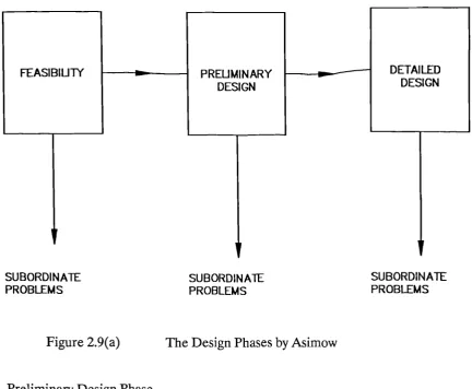
Figure 2.9(a) The Design Phases by Asimow
Figure 2.9(b) The Design Model by Asimow - Feasibility Design
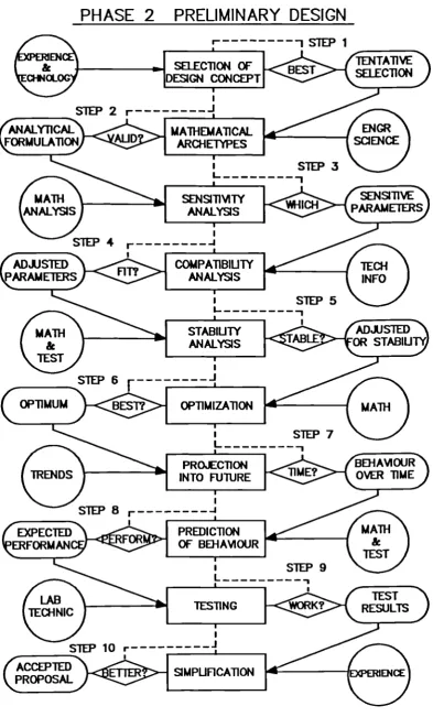
Figure 2.9(c) The Design Model by Asimow - Preliminary Design
Figure 2.9(d) The Design Model by Asimow - Detailed Design
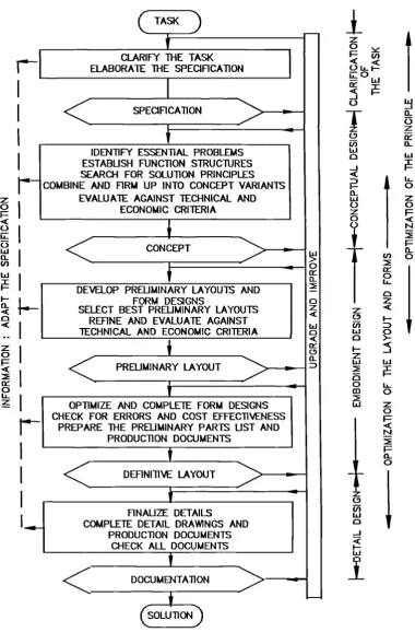
Figure 2.10 The Design Model by Pahl & Beitz
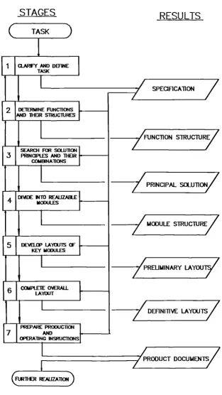
Figure 2.11 The Design Model by \TD1 2221
Figure 2.12 The Design Model by Watts
Figure 2.13 The Design Model by Marples
Figure 2.14 The Design Model by Archer
Figure 2.15 The Design Model by Finkelstein
Figure 2.16 The Design Model by Krick
Figure 2.17 The Design Model by Cross
Figure 2.18 The Design Model by Hubka
Figure 2.19 The Design Model by Seireg
Figure 2.20 The Design Model by French
Figure 2.21 The Total Design Activity Model by Pugh
Figure 2.22 Taguchi's Quality Loss Function
Figure 2.23 The Design Model by March
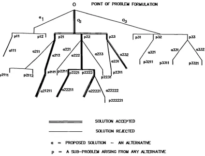
Figure 2.24 The Evolutionary Design Model
Figure 2.25 Optimally-Directed Design Architecture
ig re 2.26 The CODESIGNER System Architecture
Figure 2.27 Figure 2.28 Figure 2.29 Figure 2.30 Figure 2.31 Figure 2.32 Figure 2.33 Figure 2.34
Figure 5.1
Figure 5.2
Figure 5.3
Figure 5.4
Figure 5.5
Figure 5.6
Figure 5.7
Figure 5.8 Figure 5.9 Figure 5.10 Figure 5.11 Figure 5.12 Figure 5.13 111 113 115 117 119 120 122 137 Integrated Design Environment : A Layered Architecture
Architecture of the Integrated Design Framework
Architecture of the Schemebuilder Environment
The Structure for a System of Flexible and Continuous CAD
Architecture of the Design System MFK
IIICAD Architecture
The Design Fusion System Architecture
The Concurrent Engineering System Architecture
Traditional versus Concurrent Engineering Approach to Product Development
Cost Commitment and Maximisation of Performance Knowledge
Comparison of Design Changes
Illustration of Robust Engineering Design
Cost Drivers in Different Stages of DFD
The Structure of the Design Function Deployment System
The Design Function Deployment Design Model
The Main DFD Chart
Two Dimensional Design Matrix - Blessing
Two Dimensional Design Matrix - Simon
The Two Dimensional DFD Design Matrix
The Three-Dimensional DFD Design Matrix
One to Several Mapping of Requirements to Design Solutions 170 172 173 174 175 177 179 181 195 196 197 198 199 Figure 5.14 Several to Several Mapping of Requirements to Design
Solutions 200
Figure 5.15 Linear Design Solution Space Topology 200
Figure 5.16 Tree Design Solution Space Topology 201
Figure 5.17 Network Design Solution Space Topology 202
Figure 5.18 Morphology of the Complexity of Design in DFD 204
Figure 5.19 Increasing Complexity Through Design Stages in DFD 204
Figure 5.21 Partitioning Process in Design Structure Matrix 209
Figure 5.22 Tearing Process in Design Structure Matrix 210
Figure 5.23 Flow of the Design Process in DFD 212
Figure 5.24 Concurrent Design in Design Function Deployment 215
Figure 5.25 Multi-Application Integration 218
Figure 5.26 The Dynamic and Hierarchical Product Modelling Process
in DFD 223
Figure 5.27 Materials Needs Versus Design Life Cycle 235
Figure 5.28 Concurrent Materials and Manufacturing Process Selection
Model 236
Figure 5.29 System Architecture For Materials and Manufacturing
Process Selection System 240
Figure 5.30 Taxonomy of Multi-Attribute Decision Making Methods 244
Figure 5.31 Taxonomy of Multi-Objective Decision Making Methods 248
Figure 5.32 Classified List of all Requirements 253
Figure 5.33 Classified Design Functions 255
Figure 5.34 The DFD Interaction Matrix 256
Figure 5.35 The DFD Stage 1 Chart 258
Figure 5.36 The DFD Stage 2 Chart 259
Figure 5.37 The DFD Stage 3 Chart 261
Figure 5.38 The DFD Stage 4 Chart 262
Figure 5.39 The DFD Stage 5 Chart 263
Figure 7.1 The Design Function Deployment System Software
Architecture 282
LIST OF TABLES
Table 3.1 Design Phases 148
Table 5.1 A Morphological Chart for a Fork Lift Truck 183
ACKNOWLED GEMENTS
I wish to express my heartfelt thanks and appreciation to my supervisor and advisor, Professor Alan Jebb for giving the vision to this project. His wise counsels, insightful comments and leadership were greatly invaluable in directing me throughout the period of the research. I am also greatful for the moral support he gave me as well as being readily accessible whenever he was needed, during the course of my research.
My sincere thanks also go to my colleague, Dr Sangarappillai Sivaloganathan who contributed in no little measure to the success of this project. As the Senior Research Assistant in the Engineering Design Centre, he provided necessary leadership and guidance throughout the period of this research. He was an immensely valuable 'intellectual sparring partner'.
I am also greatful to my other colleagues in the Engineering Design Centre who provided a pleasant environment to work in, as members of a research team. Ms Hilda lu was also helpful in preparing some of my figures.
My wife and children have been very understanding and supportive throughout the research programme. My deep appreciation and gratitude go to them and to Bola Adesanya for occupying the children.
DEDICATION
To my wife Olufunmilayo Olutoyin Anne
and
my children Uyiosa and Demilade
To my teachers in the early years who had confidence in me and gave me confidence.
and
To the Ancient of Days, El Shaddai and My Ebenezer
Declaration
I grant powers to the University librarian to allow this thesis to be copied in whole or in part without further reference to me. This permission covers oniy single copies made for study purposes, subject to normal conditions of acknowledgements.
ABSTRACT
The current state of activities in the design and manufacturing industry is marked by the various CAD/CAM/CAE systems which exist as islands of automation, and are used by engineers and designers in a non-integrated and ill-structured way. Thus the design problem is examined from separate and different perspectives, rather than as a whole. The goal of this research, is to develop a comprehensive, integrated and generic design system, that will ensure the realisation of concurrent engineering in practice. To this end, Design Function Deployment (DFD) has been developed.
DFD enables the capture of customers' requirements, the establishment of design specifications and constraints in a solution neutral form, the generation of conceptual designs (architectures), the development of detailed designs (layouts), the selection of materials and associated manufacturing processes and the development of suitable production plans. The generated design solutions are optimised against a composite set of multi-criteria (attributes) in a concurrent manner for key factors such as performance, robustness and cost as well as other life cycle issues (manufacture, assembly, serviceability, reliability, environment, etc) in order to choose the most satisfying design.
DFD provides a recipe of design methods to support the designer or design team at any stage of the design process. The optimisation process involves the use of these supporting design tools (methods) encapsulated within it. DFD also provides an integrated product modelling environment which integrates both textual and geometric design information, and enables the capture of other design information related to design intent, rationale and history. The research that led to the evolution and development of DFD involved (a) a detailed investigation and research on Quality Function Deployment, QFD, a technique well suited for capturing and translating customer requirements into design specifications, (b) an extensive review of design philosophies, models, methods and systems and (c) an extensive investiga-tion into concurrent engineering.
CHAPTER 1
INTRODUCTION
1.1 GENERAL INTRODUCTION
The design and product development process has been one of the activities that man has performed over the centuries, in varying degrees and levels of details, technology and sophistication. The recent past up till now, has witnessed rapid advancements in science, engineering and technology as well as the advent of computers and the evolution of software engineering. The consequence of these developments on engineering design and product development, has also been the emergence of tools and techniques that can be regarded as computer aided design (CAD), computer aided manufacture (CAM), computer aided engineering (CAE) and computer in-tegrated manufacture (CIM) systems. These systems within the design and manufac-turing industry exist as clusters of islands of automation, and are employed by engineers and designers in an ill-structured way in performing necessary design and engineering functions during product development.
Besides these individual clusters of design tools, the product development process as practiced by many companies apart from being sequential in nature, is carried out in a compartmentalised fashion by the various functional groups, that is, marketing, sales, product planning, design, analysis, manufacture, testing, etc. This compartmen-talisation of design activities commonly regarded as the 'over the wall' approach to product development, further encouraged the segregation of the cluster of tools highlighted above.
The consequences of the compartmentalisation of design activities, in addition to the engineering tools existing as islands of automation, are the several difficulties and limitations that most companies have to contend with. Key amongst such limitations and difficulties are: (a) the rigid sequence of design decisions that characterise the design process, (b) the manual labour cost of defining, recording and communicating design details, (c) the lack of consideration of downstream issues such as production planning, maintenance, producibility, supportability, etc, early in the design process, resulting in costly design changes, (d) the fragmentation of design data and lack of consistency in design representations, (e) the loss of design information about the product and/or design intent, as the design progresses, and (f) lack of cost informa-tion and cost estimainforma-tion tools.
with the view put forward by the Duke of Edinburgh [1] who said that :" The wealth
of a nation, and all that implies, depends in fact upon the efficient organization of its
resources both natural and industrial as well as human. In this organization the engineer
bears the chief responsibility. In his viewpoint as the chairman of the Design
Management Committee (DMC) of the Science and Engineering Research Council (SERC), Professor Paul Braiden wrote in the engineering design newsletter [2] that
Engineering design, closely coupled to an efficient, responsive manufacturing system, producing reliably and repeatedly what the customer wants at an acceptable price, lies at the heart of every buoyant modern economy", thus reinforcing the earlier viewpoint.
In the past, most manufacturers did not consider issues relating to customers' perception and acceptance of their products. This was partly due to the fact that competition was not rife, and customers had no choice but to accept whatever they got. In today's world however, customers have become more sophisticated; demand-ing more variety of products as well as favourdemand-ing 'environmentally friendly' products, this being an offshoot of the increased range of available choices and fierce market competition. Customers are now prepared to pay more for products as long as they contain high technological content, exhibit high quality and reliable performance as well as being aesthetically pleasing and ergonomically acceptable.
A further consequence of increased competition in the market place is the increasing pressure on manufacturers to release their products early, i.e. on 'Time to market'. The term 'Time to market' can be generally defined as the elapsed time between
product definition and product availability. In addititon, the current wave and
emergence of new and improved products, extensions and expansions of product lines, revisions and enhancements of products, thus creates additional pressures on manufacturers to keep a steady stream or flow of new products into the market place [3]. A major influencing factor in achieving 'Time to market', is the design process, which has significant impacts on the downstream functions of product development. Faulty, hurried or inadequate product definition and design, usually results in design changes in the form of engineering change orders (ECO's), which are always costly in both time and money, irrespective of whatever sector of industry. Furthermore, the later these design changes are implemented in the development cycle, the more costly the implementation.
The need to address the issues discussed so far, led to the emergence of the concurrent engineering paradigm.
Concurrent engineering, (also known as simultaneous engineering, forward en-gineering, parallel enen-gineering, life cycle enen-gineering, and so on), has received world wide acclaim as a progressive approach to product development. The consequence of this popularity is made evident by the many definitions that have been given to it.
The most popular of these definitions is that given by Winner et al [4] which states that, "Concurrent Engineering is a systematic approach to the integrated, concurrent design of products and their related processes, including manufacture and support. This approach is intended to cause the developers, from the outset, to consider all elements of the product life cycle from conception through disposal, including quality, cost, schedule, and user requirements". A variant of the above definition which is also more encompassing is that given by Cleetus [5], which states that "Concurrent Engineering is a systematic approach to integrated and concurrent development of a product and its related processes, that emphasizes response to customer expectations and embodies team values of cooperation, trust and sharing in such a manner that decision making proceeds with large intervals of parallel working by all life-cycle perspectives early in the process, synchronised by compara-tively brief exchanges to produce consensus". An examination of the definitions on concurrent engineering, highlight certain issues that are pervasive in all of them and which can be considered as the main goals of concurrent engineering. These include the need to:
(1) improve and maintain the quality of design and the resulting product. (2) reduce product development lead time.
(3) reduce product development costs.
(4) integrate the design of a product, manufacturing and production processes. (5) resolve and manage conflicts and tradeoffs in the early stages of design. (6) breakdown barriers (walls) between product development functional groups. (7) encourage the integration and use of all company resources.
(8) respond proactively to customers and their needs. (9) parallel the design process.
(1) Establishing a focus on the client, customer or user of a product (2) Integration of the organisation
(3) Use of design and product development teams
(4) Employee involvement and participative management (5) Competitive benchmarking
(6) Focussing all activities on quality, cost and delivery
(7) Adopting a concurrent (parallel) product development process
(8) Integrating design of product with manufacture and support processes (9) Establishing strategic relationships with suppliers
(10) Integrating computer aided tools and techniques (11) Use of project management techniques
(12) Consideration of new materials and technologies (13) Synchronisation of design information and (14) Use of computer hardware and software.
Other viewpoints include those that support computer integrated manufacture, the advancement of geometric and solid modelling tools, the development of com-munication protocols to support collaborative design processes and engineering software to support concurrent engineering. In examining the concurrent engineer-ing goals highlighted earlier as well as the implementation issues enumerated above, it is evident that the operative term that runs throughout, within the context of design and product development, is INTEGRATION. In seeking to realise the benefits of good design, efforts are being made in industry to integrate all design activities in a coherent manner. For design to ensure quality, it has to be done in a planned and controlled way.
The development and adoption of a systematic methodology for design [6] and the whole product development process is hence needed to:
(1) integrate CAD/CAM/CAE systems which exist as islands of automation.
(2) integrate and support various functional groups and disciplines involved in the product development process, enable the breaking down of walls between them as well as overcome the difficulties associated with compartmentalisation.
(3) increase the efficiency and effectiveness of the design and product development team.
(4) support the synchronisation of design information. (5) support the wealth creating function of design.
(6) enable the design and product development team to respond proactively to customers in todays' market climate.
(7) enable the early release of products to the market place.
(9) enable the achievement of the goals and implementation issues of concurrent engineering.
To address this, extensive research was carried out into Quality Function Deploy-ment, Design Models, Methods and Systems and Concurrent Engineering. This led to the emergence and development of Design Function Deployment (DFD) as a comprehensive design system that would (i) ensure the integration of the quality function into design, (ii) integrate the various functional groups participating in design and product development, (iii) integrate the clusters of individual and groups of CAD/CAM/CAE tools and techniques and design related knowledge and ac-tivities and (iv) provide a platform for the realisation of Concurrent Engineering.
The DFD system also integrates:
(1) all the design knowledge (related to both the process and product) generated during the design process. In relation to the product, the integration involves both textual and geometric information throughout the stages of design.
(2) the different stages or phases of design right from product planning and concep-tual design to detailed design. In DFD, this integration is over five distinct stages starting from customer requirements capture to production planning.
(3) all necessary design methods, tools and techniques (representing the various life cycle aspects of the evolving product) to support the designer/design team during the design and product development process.
(4) the various key players in the product development process, that is, customer, marketing, sales, design, analysis, manufacture, production, testing, service, main-tenance, etc.
(5) the design of the evolving product and the associated manufacturing process(es) and other related life cycle aspects. This concept of integrating the design and manufacturing activities is akin to the concept of the shared central database aimed at integrating the CAD features of geometric modelling, analysis, testing and draughting with the CAM functions such as numerical control, process planning, robotics and factory management, as highlighted by Besant and Lui in their book [7].
1.2 AIMS AND OBJECTIVES OF RESEARCH
and techniques to assist engineers and designers to proactively respond to new and modern demands of the design and manufacturing industry, and to develop products! processes and systems that satisfy the increasing sophisticated demands and require-ments of customers and users. The system is also developed to provide a common integrated product modelling environment that captures both textual and geometric design information (data). The system will also be developed to support concurrency of the design process as well as the concurrent design of the evolving product. The resulting design system will accomodate the various aspects of the design life cycle, starting from the establishment of customer and other requirements down to the selection of materials and associated manufacturing processes and production plan-ning, as well as all forms of design information generated during the design process. Such information includes data about the design history, design intent and the rationale for the design decisions. A key desideratum of the design system will also be the need to support the design of original/innovative, adaptive and variant designs.
1.3 RESEARCH SIGNIFICANCE
Several researchers and designers have done some work in the development of design methodologies and models. A majority of such design approaches, have been associated not only with the traditional and sequential approach to design, but have been limited to particular engineering design domains. Only a few have developed methodologies that could become generic in nature.
There is however presently a lack of truly generic design systems which can ac-comodate new and emerging technologies in the modern design and manufacturing environment. Current Computer Aided Engineering (CAE) software generally focus on the geometric aspects of the design of an artefact and do not accomodate all other information such as textual data generated during the design process, as well as all the life cycle issues of the design. There is hence a need for a computer aided design system, that addresses these needs and which can help to ensure a more integrated approach to the product development process.
the quality of the design process. Several factors also influence the quality of the design process as well as the output of the process. These include: (a) the designer or design team, (b) the available tools and methods employed, (c) the existing design knowledge, (d) the management of the design process, (e) the active environment in which the process takes place, (I') the nature of the design process adopted, the procedures and the techniques employed and (g) the quality of the list of require-ments as well as the resulting specifications [9]. Hales [10], from his research work, has also established that "the effectiveness and the efficiency of the engineering design process are strongly influenced by the way the process is managed".
The consideration of the above, in addition to the increasing emphasis in industry on designing quality into a product as well as the need to get it right first time, therefore necessitates a design system that will not only ensure the realisation of concurrent engineering, but also take account of the factors highlighted above, by providing a platform for ensuring quality of the input and output of the product development process, as well as that of the transformation activities of the design process. To meet these requirements, Design Function Deployment (DFD) has been developed to enable the integration of the quality function into the design and product develop-ment process.
1.4 SCOPE OF RESEARCH
This project involved an extensive research on several design models, methods and methodologies proposed by various researchers over the last three decades, as well as Quality Function Deployment (QFD) and Concurrent Engineering.
The second stage then involved the development of the concepts of Design Function Deployment (DFD) in line with designing for quality and the provision of a platform for concurrent engineering.
Thirdly the DFD concepts were then developed into relevant, applicable and useful formats for use by engineers and designers in a manual form. This was in the form of a user manual. This then led to the final aspect of the project, which involved the development of DFD into a suitable form for computer software implementation.
1.5 OUTLINE OF THESIS
CHAPTER 2
LITERATURE REVIEW
2.1 INTRODUCTION
This chapter discusses in detail, previous and relevant research work carried out by other researchers in the area of Quality Function Deployment, Design Philosophies, Models, Methods and Systems as well as Concurrent Engineering. This involves a detailed investigation and review of these subject areas and the work done to date. This chapter provides the background for a large proportion of the research work that led to the evolution of Design Function Deployment (DFD).
The research mission of the Engineering Design Centre at City University, is to expand the discipline of Quality Function Deployment into a full design for quality methodology by the incorporation of quality into design and its maintenance throughout product life. This mission was seen as not only the integration of quality into design, but also involving very important issues such as designing a product 'right first time' and getting it early to the market at a reduced production cost and selling price. Quality Function Deployment, Concurrent Engineering and Design Models, Methods and Systems were investigated and explored in seeking to accomplish the research mission. In the ensuing discussion, each of the research areas are discussed under separate sections.
2.2 A REVIEW OF QUALITY FUNCTION DEPLOYMENT 2.2.1 Historical Background of Quality Function Deployment
Quality Function Deployment (QFD) is considered to have originated in 1972 at Mitsubishi's Kobe shipyard site, in Japan, although it appears to have apparently grown out of value analysis/value engineering [11], which was first developed about 40 years ago. Besides value analysis/value engineering, QFD has been found to show some similarities to other methodologies such as 'Structured Product Analysis' (SPA) developed by Vinson [12], Problem Solving and Decision Analysis techniques practiced by Kepner and Tregoe [13], and the Unified Program Planning technique, a precursor to Inter.ctive Structural Modelling developed by Warfield et al [14].
the early to mid 1980's QFD had grown in popularity, leading to its introduction to the USA by Professor Don Clausing of MIT and Dr Lawrence Sullivan of the American Suppliers Institute, USA. Since then several major multinationals have taken QFD on board, the key players being Xerox, General Motors, Ford, Digital Equipment, Hewlett-Packard and AT&T. In its use, QFD was founded on the belief that products should be designed to reflect customers' desires and tastes, and its was used as a kind of conceptual map which provided the means for interfunctional planning and communications between marketing, design and manufacturing departments. The resulting QFD chart also meant different things to different departments. To engineers, it was a way of summarising basic design data in usable form. To marketing executives, it represented the customer's voice and to general managers, it was used to discover strategic opportunities [151.
QFD has been defined by various researchers from various viewpoints. Some of thekey definitions are reported below.
Akao [16, 50] defines QFD as" ... a method for developing a design quality aimed at
satisfying the customer and then translating the customer's demands into design targets and major quality assurance points", while King [17] describes QFD, "as a process, focussed on improving the efficiency of the initial product design. It provides a systematic environment for designing product (service) based on customer wishes (demands) and involving all members of the producer (supplier) organisation". Hales [18] on the other hand defines QFD as "... a method for systematically focussing all organisations in your business unit towards satisfying the requirements on your product which are most important to the customer". A more elaborate definition was that b Mazur [19]. This states that "QFD is a system and procedure to identify, communicate, and prioritise customer requirements so that an organisation can optimise its products and services to exceed customer expectations. Identification is achieved through the voice of the customer analysis, communication is achieved through a series of linked matrices, and prioritisation is derived from the customer, competitors, and the vision of the company. Optimisation activities are then focussed on those areas that mean the most to the customer, beat competition, and are in line with the vision of the organisation". Another definition given to QFD by the American Supplier Institute (ASI) [43] states that "QFD is a system for translating customer requirements into appropriate company requirements at each stage from research and product development to engineering and manufacturing to market-ing/sales and distribution"
QFD emphasizes co-Operation, convergent consensual decision making, and sys-tematic linkage of engineering activities [20]. Benefits that have been attributed to QFD include, low manufacturing costs, shorter development time, easier entry into production development of product that appeal to customers and better and im-proved product quality. QFD also encourages multiple criteria decision making and recognises that product and process development is not a one dimensional exercise, but many trade-offs need to be performed before arriving at an optimal solution [21].
2.2.2 Basic Quality Function Deployment
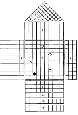
The previous section gave the introduction and historical background to Quality Function Deployment. This section however, will focus on the basic processes and constituents of QFD. Quality Function Deployment refers to the deployment of quality consciousness throughout the entire functions of company areas such as design, manufacturing, service, etc. [16]. It has also been considered as a tool for the implementation of the strategy of Total Quality Management, during product development [22]. Within the context of the construction industry, QFD is being proposed as a methodology that can be used during the early phases of a project to create more accurate decisions, focus project budgets, define project quality, and to respond to customer's needs. It is also seen as a cross-functional tool that assists technically oriented people, such as architects and engineers, to understand cus-tomer requirements sufficiently to develop priorities for these requirements that are customer-oriented and technically correct [23]. The basic planning tool used in Quality Function Deployment is the product planning chart, which is popularly referred to as the "House of Quality", and it is conceptually shown in Figure 2.1. This chart is a visualizing tool, which contains 9 rooms or blocks that represent different planning activities. These activities are described below.
Block 1 - Identification and Establishment of Customer Requirements
2 1
3
7
I}I}I)IIJI 11111
I I I I II 11111 [image:30.595.147.416.65.461.2]I I I I liol I I I I
Figure 2.1 The Basic Quality Function Deployment Chart
A popular technique for this process is known as the Kawakita Jiro (U) diagram where the customer requirements are organized into affinity groups [24]. The primary requirements represent the strategic top level requirements and set the strategic direction for the product. The secondary requirements which are the elaboration of the primary requirements, represent the tactical requirements. They indicate more specifically what can be done to fulfill the corresponding strategic or primary requirements. The tertiary requirements are the sub-divisions of secondary requirements, and they indicate more specifically how the secondary requirements can be fulfilled [25].
Block 2 - Prioritization of Customer Requirements - The 'Quality Plan'
direct market research with customers and results in what is known as the 'Quality Plan'. Quality Plan is the process of weighting the tertiary customer requirements, taking account of the customers' rating, sales advantage and quality target improve-ment factors. The process of constructing the 'Quality Plan' involves firstly, rating each tertiary customer requirement based on the degree of importance to the customer (usually on a scale of 1 - 5), the degree of improvement needed (i.e. the ratio of the targeted rating by the customers to the current rating of a company's product from competitive benchmarking) and sales advantage (where the values 1.5,
1.2 and 1.0 represent very important, important and not important respectively). These weights should be applied with caution as they change the relative importance of the requirements quite considerably. The absolute importance rating of each teritiary customer requirement is the product of the ratings obtained from the above three contributing factors. Then the relative ratings of the teritiary customer require-ments are obtained by normalising the absolute values on a scale of 1 to 9.
Block 3 - Establishment of Design Requirements - The Quality Elements
Design requirements, also referred to as substitute quality characteristics, corporate expectations for the product or engineering characteristics, are known as the 'HOWS', and then represent the design attributes (voice of the engineer) that fulfill the customer requirements. They are usually translated from the customer require-ments. These design requirements must be actionable and measurable, in order to ensure competitive advantage and that the design team is working to the same requirement. The final development of the design requirements, is attributetd to two sources, that is, deployment from the customer requirements and then amplification from functional requirements (product expectations characteristics). Once the design requirements have been compiled, they are also categorised into primary, secondary and tertiary design requirements, in a similar way as done for customer requirements using techniques like team voting and the U method [24].
Block 4 - Setting of Target Values for Design Requirements
Block 5 - Development of the Relationship Matrix [24]
This involves determining which design requirement influences which customer requirements and by how much. Furthermore, to overcome the traditionally poor translation of the customer requirements into design requirements, the design team assesses the fidelity of the design requirements to the customer requirements, with the help of the relationship matrix. The strength of the positive response of a design requirement to customer requirements (strong, medium, weak, or negligible) is expressed by different symbols or numbers. When numbers are used, the numbers 9, 3 and 1 are used to represent strong, medium and weak relationships respectively. In filling out the relationship matrix, it is important that there is a consensus amongst members of the design team for each relation that is represented in the cell. If any rows are left empty, the team has to develop design requirements to satisfy the customer requirements. On the other hand, if any empty columns appear, it is either the market research did not address all features of the product or those particular design requirements are unnecessary or redundant.
Block 6 - Development of the Correlation Matrix
This block which represents the 'roof' of the 'House of Quality', is used to consider the possible interactions (which could be interferences or synergies) between the derived design requirements, in order to identify areas of inherent conflicts between the design requirements early in the design process. Premature tradeoffs should however be avoided. The use of the matrix helps to avoid making engineering changes and a substantial amount of rework. The correlation matrix helps to provide insight into needed communications between design teams that comprise the product development team, as well as helping to optimize the entire product, avoiding suboptimization.
Block 7 - Competitive Benchmarking with Customer requirements
company's product, and hence identify targets, goals and areas for competitive advantage.
Block 8 - Competitive Benchmarking with Design Requirements
Here both competitive products and a company's own product are benchmarked, against the design requirements, that is, the 'Hows', translated from the customer requirements. The aim here is also to determine targets for the design requirements which satisfy the customer requirements and hence exceed competitors design.
Block 9 - Assessment of Technical Difficulty
This block contains numeric values usually on a 1 - 5 scale, used to indicate the level of technical difficulty involved in the achievement of any particular design require-ment. The difficulty may be related to design, manufacturing, suppliers or competi-tive pressures, but its determination should be tailored to the problem under consideration [26]. Depending on the level of difficulty indicated for the design requirements, necessary actions can then be taken to resolve the impending difficul-ties, either by carrying out research experiments and tests, utilising new materials and technologies or seeking expert opinions.
Block 10 - Evaluation of Importance of Design Requirements
This block contains the evaluations of design requirements that are derived from the relative significance of customer requirements to achieve the determined target values of design requirements. Based on the strength of the relationship between customer requirements and design requirements (scale of 1,3 and 9), the importance of the design requirements is the sum of multiplying the relationship by the impor-tance rating of the customer requirements. This resulting value represents the absolute importance of the design requirement. The absolute values for all the design requirements are then normalised on a scale of 1 to 9, to obtain the relative importance values. The importance rating is useful for prioritising efforts and for making design trade-offs.
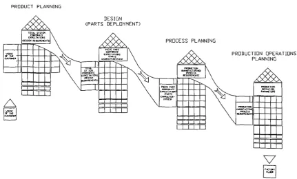
establishing the functions of each part following the preparation of a bill of parts and determining the critical parts characteristics necessary to achieve the critical design requirements from the product planning stage. In the Process planning stage, the critical parts characteristics are also selected and become the 'Whats' and are deployed into process planning parameters, that is the 'Hows'. The depolyment process involves determining potential materials, manufacturing processes and shape, after which a master flow diagram is constructed, and from which the critical process planning parameters are determined. In the fourth and final production operations planning stage, the critical process planning parameters from the previous stage are selected and then deployed into production operations parameters. This involves determining the critical control, production maintenance, mistake proofing, education and training requirements, etc, to accomplish the production operations parameters. This deployment through each of the four stages of QFD is shown in Figure 2.2.
PRODUCT PLANNING
DESIGN (PARTS DEPLOYMENT)
TOTAL TATTOO
PROCESS PLANNING
PRODUCTION OPERATIONS PLANNING
OC T IF C TOO RCFJIIFK010
V
The basic form of QFD has been shown to exhibit the following main advantages [22]:
(i) It helps to improve communication throughout the various departments and functions within a company, as well as helping them to focus on their collective tasks as they participate in the product development process. Thus it's effectiveness downstream from stage 2 to 4, diminishes.
(ii) It provides a structured way of designing in quality into the product or system, and ensures that the product development process is guided by the need to satisfy the customers' requirements
(iii) The house of quality charts can be used as databases to build and store a lot of design knowledge during the product development process.
On the other hand certain limitations have also been observed in the use of QFD, and these include:
(i) In translating to the second, third and fourth stages involving the determination of piece parts parameters, process parameters and production operations respective-ly, QFD does not provide a systematic approach, and it is done implicitly by engineering knowledge. Thus it's effectiveness downstream from stages 2 to 4 diminishes.
(ii) For complex products, it is impossible to derive piece part design parameters, while only using product specifications as input information, as it does not account for multiple product levels of system, subsystem and components or parts.
(iii) Basic Quality Function Deployment is only suited for the development of simple and conceptually static products. For products that are conceptually dynamic, which then require the consideration of different product concepts, there is no provision within basic QFD to handle them.
The above limitations led to the development of further enhancements to the basic QFD, and this is described in the proceeding section
2.2.3 Enhanced Quality Function Deployment
The deployment through multiple levels of the product or system, involves a break down of the design phase of basic QFD into Total System design, Subsystem design and Piece Part design. This was considered to enable the development of complex products that would otherwise have been difficult using basic QFD. Since both the process and production operations plaiming stages are influenced by the product's structure, both stages are also broken down into subphases as shown in Figure 2.3.
Ker. T3 - ToI System. 63- Subsystem, PP - Piece Part
The charts used during the above sub-phases are essentially the same as those of basic QFD. The only difference is the shift from the one-dimensional, straight forward deployment in the direction of the factory floor, to a two dimensional deployment forward to the factory floor and downward from the total system level to the piece part level. The procedure followed in enhanced QFD enables product development teams to commence with process planning before the design phase is completely finished. This leads to a considerable speed-up of product development and therefore contributes to the implementation of concurrent engineering [28].
The introduction of Pugh's concept selection into basic QFD, was aimed at extending the applicability of QFD to the development of conceptually dynamic products. The Pugh's concept selection method uses a visual chart as a selection tool. In this chart is recorded the available concepts as headings of the columns and the selection criteria as headings of the rows - Figure 2.4. These available concepts are usually represented in the form of sketches for ease of visualisation. The selection criteria are derived from the system specifications (process specifications) that are provided by the corrseponding QFD matrix (Figure 2.3). At the beginning of the selection process, an initial datum is usually chosen. This datum might be a dominant product or process design which already exists and relates to the selection area under consideration. Each of the proposed concepts is then compared with this datum with regards to its ability to satisfy the selection criteria. The relative abilities of these concepts with respect to the datum, are usually expressed by simple symbols like "+" meaning superior, meaning inferior and "S" meaning same, which are inserted into cells of the chart. A score pattern in terms + ", and "S" is obtained by adding up the number of symbols. The selection procedure is repeated several times while using the best concept of the preceding run as a new datum. The hope of using Pugh's technique is that at the end of the process, a superior design will emerge. Within enhanced Quality Function Deployment, concept selection supports both the for-ward and downfor-ward deployment [22].
con-sideration. The plot is then used to observe the performance of the products and then eventual decision on the most viable ones. The matrix analysis technique involves essentially the application of the Pugh concept selection method to existing products. This evaluation is done for existing products to select the competitive benchmark products that are used in the subsequent benchmarking activities in the 'House of Quality'. This reverse concept selection activity also provides insights into the strengths of existing designs, which is helpful for subsequent concept development and selection for new products. Both parametric and matrix analysis are advocated to be done early in the product development process. For static concepts, contextual analysis should be completed before the concept development and selection for new products begin. For dynamic concepts, the contextual analysis and new concept development and selection will be iterative. They will guide each other and converge to compatibility as they are mutually developed.
Concepts
enIa____
0
0
+
-
4- - +
--B - s + + s 'A'
__ + - 4- +
-B s s +
-E - + - s s
2 2 1 2 2 1 2 - 1 2 2 1 4 2 1
Ranking 2 3 1 2 3 2
Figure 2.4 Pugh's Concept Selection Process
The benefits attributed to Enhanced Quality Function Deployment in comparison with Basic Quality Function Deployment are : (i) Support of the development of complex products, (ii) Support of the development of conceptually dynamic products and (iii) Reduction in product development time. Inspite of the above advantages, Enhanced QFD was also found to have the following limitations [22]: (i) The systematic determination of design requirements for subsystems and piece parts, is not provided, (ii) The deployment decision as to which design requirements for a Total system are important for the design of a particular subsystem, and therefore to be deployed down to the corresponding QFD matrix is not supported systematically, (iii) The consideration of events that lead to a deviation from the ideal performance of a product is not provided.
2.2.4 Extended Enhanced Quality Function Deployment
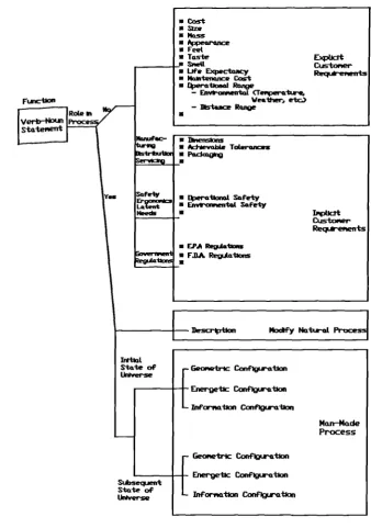
To overcome the above limitations of Enhanced Quality Function Deployment, Functional Analysis was integrated into it. The aim of this was to be able to analyse design requirements in more detail. Design requirements, also referred to as cor-porate expectations are described as measurable terms that determine the ideal performance of a product. However, the ideal performance of a product can be seen as a function, that is performed under constraining conditions [30]. As a result, it can be considered that design requirements describe the conditions under which a product has to perform a function in engineering language, that is in measurable terms. Extended Enhanced Quality Function Deployment hence provides a sys-tematic determination of design requirements for product elements based on the analysis of conditions under which the function of these elements are to be peformed.
- Coet
lze - Mass
JpeQrw1ce Feet Tas-• I•U
• Life Expectolicy • Nam-tennce C•t • f4,etQuonai Range
- EiivPoirL ar.ba-,.
Fia'ctI011 - Wrsther, etc.)
Re Ro&e Ii
Verb-N0J S-tatei'ietrt
C 1hienis
• tIevnbs ToLro,s
C Podcum9
• t%)eraUonol Safety • EnvT'o,eiento.t Safety
C
Qr Reer,ents
• EPA RegiAatlons
• F.BA Rja-tIo,
Description Mocify Naiteat Pr
rConfl
I +
Energetic ConfigxtIon
L
INan-Made Process
r GeOilti'IC Conflgtration Energetic Conrution SiAseaent
State of
[image:40.595.103.442.63.545.2]for,,ation Confation
Figure 2.5 The Amplification Sub Tree
The next stage, that is, the Design of the Total System in Extended Enhanced QFD, proceeds in a similar manner as the Product Planning stage, except for some few exceptions, which correspond to the procedure of "Deployment through-the levels" (Total System, Subsystems and Piece Parts). The procedure adopted is as follows:
(1) Subfunctions of the product's Top function are first determined without regard to any design concept. This is done in order to gain a clearer understanding of the structure of the concept that is to be selected during Total System Design.
(2) In the case of dynamic Total System concepts, a Total System concept for the product has to be selected. Here only concepts that have been proven as feasible and robust are evaluated.
(3) After selecting a concept, the functions of the subsystems of the Total System are compared to the top function and the subfunctions which were determined before concept selection. This function level check serves to identify the position of a function in the function tree. The relationship among the functions is also analysed. (4) A function tree is then developed which represents the relationships among all functions revealed by the Extended Enhanced QFD. The function tree is a valuable communication tool during design which documents the interactions among func-tions. In creating the function tree, the Product Structure Element (PSE) Function Assignment Matrix is introduced and used to gain a clear overview of the assignment of functions to Product Structure Elements. The Product Structure Element (PSE) Function Assignment Matrix is developed simultaneously to Extended Enhanced QFD during Design and contains all functions of the PSE in the rows and related hardware components in the columns. Using the matrix, each function is then assigned to a PSE, as shown in Figure 2.6.
I F2 is the Means to Achieve
4
the GoaJ-Functon F1Relationship
IMa1x AND Reiationshlp
F3 Is performed by PSE3
(5) In the final step, the Amplification Sub-Tree of the subfunctions are created. These subfunctions are then assigned to related design requirements (corporate expectations) for the Total System, based on the fact that design requirements for a higher level system, which are related to amplifications of functions performed by a subsystem, provide information that is required for the design of the subsystem.
For the Subsystem and Piece Part Design, similar approaches to the steps above, are followed with some modifications. In the case of Subsystem design, interactions between subsystems are usually determined. The subsystem that has the highest interaction with other subsystems, then has the highest priority during design. The design of all the subsystems then proceed concurrently. In the case of Piece Part design, the process is split into two parts, that is, Part Formation and Part Finishing. This is done in order to focus the Extended Enhanced QFD activities for design on particularly critical Piece Part design decisions. For Piece Part Formation, Extended Enhanced QFD is applied to the most important Piece Parts while for Piece Part Finishing, Extended Enhanced QFD is only applied to the design of highly critical part features. The procedures followed in the application of Extended Enhanced QFD to Product Planning, and Product Design of Total System, Subsystem and Piece Part is shown in Figure 2.7.
2.2.5 Further Extensions to Quality Function Deployment
Some other enhancements and extensions have in the recent past, been added to Quality Function Deployment and they are discussed in the proceeding sections.
Requirements and Failure Causes Analysis (RFCA)
Sontow and Clausing [22] report on some work carried out at MIT, in seeking to iprove on Enhanced Quality Function Deployment (EQFD). The work resulted in the development of Requirements Failure Causes Analysis (RFCA) [9]. This in-volved the integration of Failure Mode and Effect Analysis (FMEA) into Extended Enhanced Quality Function Deployment. The goal of this work was to provide : (a) Systematic determination of the product's ideal performance guided by customer requirements, (b) Systematic determination and avoidance of events that cause deviation from the products ideal performance as early as possible during product development, (c) Systematic analysis of the relationship between causes and effects of undesired events and (d) Evaluation of design requirements (corporate expecta-tions) and undesired events in order to focus on critical aspects during quality planning.
customer requirements are then structured with regard to the system level, and then finally translated into design requirements (corporate expectations) for the product based on the analysis of the product functions.
Phase 2, that is, the Design phase is used to select design concepts for components of the products based on the component functions, design requirements for the components, and causes and effects of failures. The procedure involves first the determination of design requirements for subsystems and piece parts based on the component functions. Then the causes and effects of failure modes are determined, as well as the relationship among failures and design requirements. Based on this information, optimal design concepts for the components are then selected. In order to guide the planning of the design and process activities, the design requirements and causes of failure are also systematically evaluated. In phase 3, corporate expec-tations for assembly and production processes are first determined taking into account the design requirements from phase 2. Then 'noise factors' that cause failures or production variations are considered systematically. Again the planning activities during process planning are guided by the systematic evaluation of cor-porate expectations for the processes and 'noise factors' that affect them. Using the
above information, optimal assembly and production processes are then selected. Phase 4, involving operations planning for critical assembly and production processes is conducted concurrently with process planning. Operations that are required in order to assemble and manufacture the product are derived from the output of Phase 3, assembly and production processes. In addition, quality assurance measurements are determined with regards to 'noise factors' that affect the performance of assemb-ly and production processes.
Quality Function Deployment for Production
capability of a critical process step. Finally, Taguchi methods and/or the process database can be utilized to set the target values for the process parameters.
In the case of Phase 4, the output results of Phase 3 constitute the starting point. Using the information from Phase 3, Phase 4 commences with the establishment of the Production Operations Planning Chart per machine. This chart contains the critical process steps performed at one machine. The first activity in this step is the determination of important production operations that are necessary to control a process parameter. The matrix in the chart is then used to define the appropriate tasks of a production operation or to describe the device (a control document or a control instrument) that has to be applied. The second step in this phase involves the establishment of the Process Control Sheet per machine. The Process Control Sheet per machine, also enables source inspection of the production process in order to minimize variation.This is to assure that process control sheets will be created at least for the production of the critical part characteristics. The activities in this step commences with the determination of the necessary information for a process control sheet. Such information can be obtained from a variety of sources such as the charts of Phases 2 and 3, and they include data for piece parts characteristics, piece part process planning as well as those from the process database. Finally the data for production operations are then entered into the Process Control Sheets.
Quality Function Deployment and Interpretive Structural Modelling
The application of Interpretive Structural Modelling (ISM) to Quality Function Deployment [20], was motivated by the following reasons:
(1) It was considered that there was considerable synergy between QFD and the structural modelling techniques. The basic formats for QFD and Unified Program Planning (UPP), a precursor to Interpretive Structural Modelling (ISM), were considered to be very similar [4]. The objective of QFD and structural modelling techniques is the same, that is, to improve the problem solving process by enhancing the understanding of the components of a problem and its often complex inter-relationships. Structural Modelling techniques, are attempts to improve the ability of designers to surround and fully understand complex problems.
(2) Structural Modelling techniques may help to provide internal consistency to the tree hierarchies created during the process of design. Engineers commonly develop functional trees for the product being designed. The establishment of requirements in QFD also involves hierarchical structuring in the form of trees.
(4) There is promise that the matrix partitioning techniques embedded in ISM could increase the efficiency of constructing QFD matrices.