SMART ANTENNA FOR HANDSET APPLICATION
NOR HALIMAH BINTI MUZAMMEL
This report is submitted in partial fulfillment of the requirements for the award of Bachelor Electronic Engineering (Telecommunication Electronics)
With Honours.
Faculty of Electronic and Computer Engineering Universiti Teknikal Malaysia Melaka
*F.LAYSf4
UNIVERSTI TEKNIKAL MALAYSIA MELAKA
$
FAKULTI KEJURUTERAAN ELEKTRONIK DAN KEJURUTERAAN KOMPUTER-
-
BORANG PENGESAHAN STATUS LAPORAN PROJEK SARJANA MUDA I1Tajuk Projek : SMART ANTENNA FOR HANDSET APPLICATION
Sesi
Pengajian : 200712008
Saya NOR HALIMAH BINTI MUZAMMEL
(HURUF BESAR)
mengaku membenarkan Laporan Projek Sarjana Muda ini disimpan di Perpustakaan dengan syarat- syarat kegunaan seperti berikut:
1 . Laporan adalah hakmilik Universiti Teknikal Malaysia Melaka.
2. Perpustakaan dibenarkan membuat salinan untuk tujuan pengajian sahaja.
3. Perpustakaan dibenarkan membuat salinan laporan ini sebagai bahan pertukaran antara institusi pengajian tinggi.
4. Sila tandakan ( ) :
(Mengandungi maklumat yang berdarjah keselamatan atau
r l
SIJLIT* kepentingan Malaysia seperti yang termaktub di dalam AKTA RAHSIA RASMI 1972)TERHAD* (Mengandungi maklumat terhad yang telah ditentukan oleh
organisasilbadan di mana penyelidikan dijalankan)
(TANDATANGAN PENULIS)
Alamat Tetap: NO. 3-3 JALAN SULAIMAN,
84 000 MUAR, JOHOR
Disahkan oleh:
(COP DAN TANDATANGAN PENYELIA)
W NB AWANG TEH
Pensyarah
FakuRi Kej Elektronik dan Kej Kmputer (FKEKQ Universlti Teknikal Malaysia Melaka (UTeM).
Karunq Berkuna 1201,
Ayer Kwoh, 7545a Melaka
DECLARATION
"I hereby declare that this report is the result of my own work except for quotes as cited in the references".
Signature Author Date
"I hereby declare that I have read this report and in my opinion this report is
sufficient in term of the scope and quality for the award of Bachelor of
Electronic Engineering (Telecommunication Electronics) With Honours."
Signature
Supervisor's Name : Encik Azman Bin Awang Teh
ACKNOWLEDGEMENT
First of all I would like to thank my lord Allah who has helped me to
complete this thesis. I could not have completed my dissertation without the support
and help fiom several people.
First, my sincere appreciation goes to my supervisor, Encik Azman Bin
Awang Teh who has provided valuable support and encouragement over the past
year. I also would like to express my gratitude to all my friends and colleagues for
their care and encouragement.
Lastly, my deep appreciations are for my family and relatives especially to
my parents for their f i l l of support and encouragement. This work would not have
been achieved without the ultimate support from them. I would like to say that no
vii
ABSTRACT
Mobile communication technology has been developed rapidly in the past
decade and it has been already dramatic impact in our life. In the last few years, the
development of smart antenna systems represents one of the interested principles in the
information and mobile communication field. Based on the previous works that had
done before, there have a lot of researches and experimental in developing the smart
antenna system. The smart antenna systems need to be designed with simple
calculations, fast and in a small size. This can be done by develop the block set based
on the value which is related for transmitted and received signal by using the Matlab
Simulink software. The objective of the project is to study and understand the principles
and characteristics of the smart antenna system. The block set that had been developed
will be used to process the signal in both transmitter and receiver where this is applied
to multiple antennas. This project is started with literature review on smart antenna in
handset application. Then, the developing on block set of transmitter and receiver is
done before it testing and modified again. The process will be end on the testing and
.
. .
Vlll
ABSTRAK
Teknologi komunikasi bergerak telah dibangunkan dengan pesat dalam
beberapa puluh tahun yang lepas dan ia memberi impak yang besar kepada kehidupan
kita. Beberapa tahun yang kebelakangan ini, kemajuan di dalam sistem alat pemancar
pantas telah mewakili salah satu petunjuk yang begitu penting dalam bidang
informasi dan komunikasi bergerak. Berdasarkan kepada kajian yang terdahulu,
terdapat pelbagai eksperimen dan ujikaji dalam pembangunan system alat pemancar
pantas. Di dalam projek
ini,
system alat pemancar pantasini
hendaklah direkabentukberdasarkan nilai pengiraan yang mudah, rekabentuk yang bersaiz kecil dan
berkeupayaan pantas. Projek ini boleh dijalankan dengan membina blok yang
berdasarkan alat penerima
dan
alat pemancar. Blokini
boleh di hasilkan denganmenggunakan perisian Matlab Simulink. Objektif utama projek
ini
adalah untukmemahami ciri-ciri dan prinsip-prinsip yang digunakan dalarn aplikasi telefon tangan.
Blok yang dibina berdasarkan nilai-nilai tertentu akan digunakan dalam memproses
isyarat di antara alat pemancar dan alat penerima
untuk
pelbagai pemancar (antenna).Projek ini akan dimulai dengan kajian latar belakang untuk aplikasi telefon tangan
di
mana selepas itu blok-blok untuk alat pemancar dan alat penerima akan dibina dengan
menggunakan perisian Matlab Simulink. Akhir sekali, kerja-kerja pengujian dan
TABLE OF CONTENTS
CHAPTER TITLE
TITLE OF PROJECT
VERIFICATION FORM DECLARATION SUPERVISOR'S APPROVEMENT DEDICATION ACKNOWLEDGEMENT ABSTRACT ABSTRAK
TABLE OF CONTENTS
LIST OF TABLE
LIST OF FIGURES
LIST OF ABBREVIATIONS
I INTRODUCTION
1.1 Introduction
1.2 Objectives
1.3 Problem Statements
1.4 Scope of Work
1.5 Methodology
I1 BACKGROUND STUDY
2.1 Antenna History
2.2 Smart Antenna Analogy
2.3 Categories of Smart Antenna Systems
2.3.1 Switched Beam Antennas
2.3.2 Dynamic Phase Arrays
2.3.3 Adaptive Antennas
2.4 Multiple Access Technique
2.4.1 Frequency Division Multiple Access (FDMA)
2.4.2 Time Division Multiple Access (TDMA)
2.4.3 Code Division Multiple Access (CDMA)
2.4.4 Space Division Multiple Access (SDMA)
2.5 Modulation Technique
2.6 Direct Sequence Spread Spectrum
2.6.1 Direct Sequence Spread Spectrum Using BPSK
2.7 The Attributes of CDMA
2.8 CDMA Transmission
2.9 Smart Antenna's Benefits
111 METHODOLOGY
3.1 Project Methodology
3.1.1 Flow Chart
3.1 -2 Explanation of the Flow Chart
3.2 Simulation Design
3.2.1 CDMA Model Used
3.3 Block Set Used
3 -3.1 Data Source
3.3.3 Spreader and Despreader 3.3.4 AWGN Channel
3.4 BER Calculation
3.5 Advantages of Matlab Simulink Software
IV RESULTS AND DISCUSSION
4.1 Block set Development 4.1.1 Block Set Figure 4.2 Result
4.2.1 Result of Downlink Transmission 4.2.2 Result of Uplink Transmission 4.3 Selection of CDMA Block Set
CONCLUSION AND RECOMMENDATION
5.1 Conclusion
5.2 Recommendations
LISTS OF TABLE
NO TITLE
2.1 CDMA Attributes
PAGE
LIST OF FIGURES
TITLE PAGE
Human Analogy
Electrical Equivalent
Switched Beam Antenna
Adaptive Antenna
Frequency Division Multiple Antenna (FDMA)
Time Division Multiple Antenna (TDMA)
Code Division Multiple Antenna (CDMA)
Space Division Multiple Antenna (SDMA)
Binary Phase Shift Keying (BPSK)
Quadrature Phase Shift Keying (QPSK)
Direct Sequence Spread Spectrum
Direct Sequence Spread Spectnun System
Example Direct Sequence Spread Spectrum
Flow Chart
CDMA System Model Used For Downlink Transmission
CDMA System Model Used For Uplink Transmission
Parameter Setting For Data Source
Parameter Setting For Modulator
Parameter Setting For Demodulator
Parameter Setting For Spreading
Parameter Setting For AWGN Channel
BER Calculation
Parameter Setting For BER Calculation
CDMA System For Downlink Transmission
CDMA System For Uplink Transmission
Data Source For Downlink
After Modulation For Downlink
After Spreading Result For Downlink
After Channel Result For Downlink
Despreading Result For Downlink
Data Source For Uplink
Modulation For Uplink
Spreading For Uplink
Channel For Uplink
LIST OF ABBREVIATIONS ASK AWGN BER BPSK CDMA FDMA FSK PN PSK QPSK SDMA SIR SNR TDMA
Amplitude Shift Keying
Add White Gaussian Noise
Bit Error Rate
Binary Phase Shift Keying
Code Division Multiple Access
Frequency Division Multiple Access
Frequency Shift Keying
Pseudo Noise
Phase Shift Keying
Quadrate Phase Shift Keying
Space Division Multiple Access
Signal to Interference Ratio
Signal to Noise Ratio
CHAPTER 1
INTRODUCTION
1.1 Introduction
In nowadays technology, the cellular communications systems have speedily
grown up. One of the part technologies used in this system is smart antenna
technology for handset. A smart antenna or an adaptive array antenna consists of
multiple antenna elements at the transmitting and receiving part. By using an
appropriate set of antenna weights which are provided in software, the desired beam
from the antenna can be programmed. The concept of spatial diversity has been
expanded to use some digital signaling processing (DSP) block set and dynamically
generate the binary input pattern based on the positions of transmitter and receivers
itself. This smart antenna can use a technique of multiple-input multiple-output
(MIMO) which can provided multiple signals in the antenna that give the better
performance.
Smart antenna technology contains many advantages to telecommunication
system such as can greatly reduce the interference; increase the system capacity in
communications channels and to enlarge the radio link quality. It can be seen that
develop the block set in Simulink to generate the signal beam, testing and modifying
the block set using CDMA block set.
1.2 Objectives
The objectives of this project are:
1. To understand the principles and characteristics of the smart antenna for
handset application.
2. To study the Sirnulink Block set and CDMA technology in process the signal
at the transmitter and receiver.
3. To develop the block set of downlink and uplink in Sirnulink for smart
antenna applications.
1.3 Problem Statement
Nowadays telecommunication technology required the fast, simple and small
antenna that can be able to give the best performance. In order to propose the small
and smart antenna, the work of design and develop the smart antenna for handset
applications consist of big challenges as the limited size compare to actual handset.
Therefore the suitable smart antenna should have very compatible design and
architecture. Besides that, there is a challenge to develop the suitable simulation
methodology and the accurate modeling of channel characteristics, interference and
implementation losses. To overcome this problem, the block set for process the signal
1.4 Scope Of Work
The scope of work for this project can be divided into three parts; the first is
the literature review. This work can be done by analyzed and study the principles of
smart antenna in Simulink in order to get the better results. For the example, in
Simulink there are a lots of types of block set can be used in order to analyze the
signal in input of binary number, such as the binary phase shift keying (BPSK),
quadrature phase shift keying (QPSK), and others. Then, the second part is
developing the transmitter and receiver by using the block set in Simulink. The
developing of this will be done by using Matlab Simulink for transmitter and receiver.
Lastly, for the final part is testing the block set. By this, the setting will be change in
order to get the output signal. If there any improvement can be made, then the setting
of the block set will be modified.
1.5 Methodology
This project will start with the background study of smart antenna in handset
application. This is done by find out all the journal, articles and books that related to
this project either in website or any materials. After understanding all concepts which
is relating, the study of software is done. In this project, developing of the block set of
transmitter and receiver is done by using the Matlab Simulink 7.1 software. All of
these block set is develop by appropriate block set that relate with the transmitter and
receiver before both of it will be combined together as a system. After the entire
block set for transmitter and receiver is done, the testing and modification can be
CHAPTER 2
BACKGROUND STUDY
2.1 Antenna History
Antennas have become increasingly play an important role in our life and
society until now they are indispensable since the era of Hertz and Marconi [I]. They
are everywhere; at our homes and workplaces, on our cars and aircraft, while in ships,
satellite and even as pedestrian we are carrying them. Although antennas may seem to
have bewildering, almost infinite variety, all operate in the same basic principle of
electromagnetics.
Antennas are our electronic eyes and ears on the world. They are our links
with space. They are important and integral part of our evolution. Antennas have been
around for a long time, millions of years ago. But in last 100 years ago, they have
acquired a new important as the connecting between radio system link and the world
outside. The first radio antenna was created by Heinrich Hertz, a professor at the
Technical Institute in Karlsruhe, Germany. In 1886, he assembled apparatus of a
complete radio system operating at meter wavelengths with an end-loaded dipole as
Although Hertz was the leader and father of radio, his invention remained a
laboratory curiosity until 20 years old Guglielmo Marconi of Bologna, Italy went on
to add tuning circuits, add with big antenna and ground system for longer wavelength,
and lastly was able to signal over longer distances. On mid December 1901, from the
transmitting station that he had constructed at Poldhu in Cornwall, England, he
shocked the world by receiving the signals at St. Johns, Newfoundland. Then, the
next year he started with regular transatlantic message service in spite of a suit by the
Cable Company for infringing on its monopoly of transatlantic messaging.
At the beginning of the 2 0 ~ century there is an invention that captured the
pubIic imagination as Marconi's wireIess creation. After its value at sea had been
dramatized by the S.S. Republic and S.S. Titanic disaster, Marconi was regarded with
universal fate and admiration seldom matched. Before wireless, complete isolation
enshrouded a ship at sea. Disaster could strike everything without being aware that
anything had happened. Then, Marconi became the Wizard of Wireless.
During World War 11, the advent of radar which named centimeter
wavelengths become famous and the entire radio spectrum opened up to wide usage.
Thousands of communication satellites bristling with antennas now circle the earth in low, medium and geostationary orbits. The geostationary satellites form a ring around
the earth similar to the ring around Saturn. Your hand held Global Position Satellite
(GPS) receiver give your latitude, longitude and elevation to centimeter accuracy
anywhere on or above the earth day or night, cloudy or clear.
Antennas are the essential communication link for every part such as air craft,
and ships. Besides that, antennas for cellular phones and all types of wireless devices
link us to everyone and everyhng. With mankind's activities, which expanding into
space, the needs for antennas will grow to an unprecedented degree. Antennas will
provide the vital links to and from everything out there. The
future
of antennas2.2 Smart Antenna Analogy
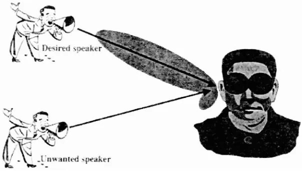
The functionality of many engineering systems is mostly can be understood
and easier when it is correlated with our human being body system [5]. Thus, to give a more understanding on how a smart antenna systems work, let us imagine a
conversation between two person in a dark room [refer to Figure 2.11. The listener
among the two persons can determine the location of the speaker when he makes any
movement because the voice of the speaker arrives at the ear, the acoustic sensor
come at different time. Then the brain, the human signal processor will compute the
direction of the speaker at the different time or delay of the voice received by the two
ears. Afterward, the brains will add the strength of the signals from each ear so as to
focus on the sound of the computed direction. In addition, if another speaker connects
in the conversation, the brain can tune out unnecessary interferers and concentrate
only on one conversation at a time. In opposition, the listener will respond back to the
same direction of the preferred speaker by orienting the transmitter which is act as
[image:21.516.104.406.426.597.2]mouth, towards the speaker.
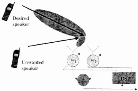
The same way is used for electrical smart antenna systems by using two
antennas instead of the two ears and a digital signal processor instead of a brain. This
can be referred to Figure 2.2 below. Therefore, after the digital signal processor
measures the time delays from each antenna elements, it will compute the direction of
arrival of the signal of interest, and then it is adjusts the excitations (the gains and
phases of the signals) to produce a radiation pattern that focuses on the signal of
[image:22.515.136.377.228.386.2]interest while, ideally, tuning out any signal not of interest.
Figure 2.2: Electrical Equivalent
23 Categories of Smart Antenna Systems
The idea behind a smart antenna is not new but it was started at early sixties
when it was the first time planned for electronic warfare as a counter measure to jamming. At that time, varying degree of costly antennas systems had used in defense
systems and for satellite communications. This is excluding diversity arrays that were
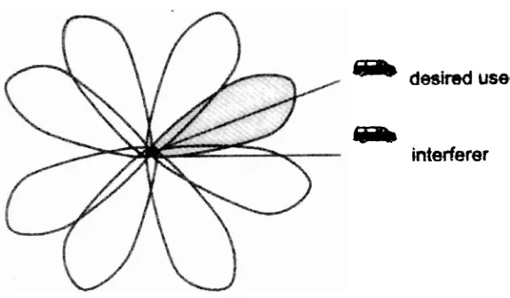
2.3.1 Switched Beam Antennas
LP
dedrsd user@a
[image:23.516.115.402.99.267.2]interferer
Figure 2.3: Switched Beam Antennas
A switched beam antenna system consists of several highly directive, fixed,
pre defined beams, formed usually with an arrays by referring to the Figure 2.3 above.
In practice, multiple beams from an array can be formed by means of beamforming
network that consists of an interwoven feed system and multiple input ports. An
example of beam forming network is the Butler matrix which consists of power
splitters and phase splitters. The system detects signal strength and chooses one of
the best beams that give the better signal performance, typically in conditions of the
maximum received power as the mobile moves throughout the cell.
Beam switching can be performed by means of semiconductor switches. In a
sense, a switched beam antenna is an extension of the conventional sector beam in
that it divides a sector into several micro-sectors. If there are no direction of arrival
information of the desired user is assumed, the desired user may not fall on the
maximum of the chosen beam. Switches beam antennas are effective in low to
moderate co channel interfering environments owing to their lack of ability to
distinguish a desired user from an interferer. If a strong interfering signal is at the
interfering signal can be enhanced far more than the desired signal with low quality of
service to the intended user.
2.3.2 Dynamic Phase Arrays
For dynamic phase arrays, it is make use of the direction of arrival information
from the desired user and steer a beam maximum towards the desired user, this
consequently improving upon the capabilities of a switched beam antenna [4]. Some
sort of tracking in dynamic phase arrays is required to constantly turn the beam
towards the desired user.
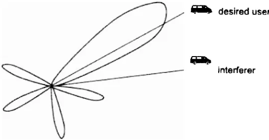
2 3 3 Adaptive Antennas
@fb desired user
mJB
[image:24.516.124.394.372.513.2]interferer
Figure 2.4: Adaptive Antenna
In an adaptive array, the weights are adjusted to maximize the signal-to
interference-plus-noise power ratio and provide the maximum discrimination against
interfering signals as referred to Figure 2.4 above [4]. An adaptive antennas will
maximize the signal to noise ratio if there occur an interferers and noise, this