UNIVERSITI TEKNIKAL MALAYSIA MELAKA
THE INFLUENCE OF WELDING PARAMETER ON BUTT
JOINT WELDING STRENGTH
This report submitted in accordance with requirement of the Universiti Teknikal Malaysia Melaka (UTeM) for the Bachelor Degree of Manufacturing Engineering
(Manufacturing Process)
by
LIM MING HAO
B050710146
DECLARATION
I hereby, declared this report entitled “The Influence of Welding Parameter on Butt Joint Welding Strength” is the results of my own research except as cited in
references.
Signature : ……….
APPROVAL
This report is submitted to the Faculty of Manufacturing Engineering of UTeM as a partial fulfillment of the requirements for the degree of Bachelor of Manufacturing Engineering (Manufacturing Process). The member of the supervisory committee is as follow:
i
ABSTRAK
ii
ABSTRACT
iii
ACKNOWLEDGEMENT
iv
DEDICATION
v
TABLE OF CONTENT
Abstrak i
Abstract ii
Acknowledgement iii
Dedication iv
Table of Content v
List of Tables viii
List of Figures ix
List of Abbreviations xi
1. INTRODUCTION 1
1.1 Background 1
1.2 Problem Statement 2
1.3 Objective 2
1.4 Scopes 2
1.5 Organization 3
1.6 The Importance of Study 3
2. LITERATURE REVIEW 4
2.1 Introduction 4
2.2 Arc Welding 5
2.2.1 Gas Metal Arc Weld 5
2.2.2 Advantages of Gas Metal Arc Weld 6 2.2.3 Limitation of Gas Metal Arc Weld 7
2.2.4 Metal Transfer Modes 7
2.2.5 Welding Parameter 10
2.2.5.1Welding Current 13
2.2.5.2Welding Voltage 13
2.2.5.3Welding Speed 13
2.2.5.4Welding Shielding Gases 14
vi
2.2.5.6Consumable Electrode 17
2.3 Welding Material 18
2.3.1 Mild Steel 18
2.3.2 Designation of Steel 19
2.4 Tensile Test 19
2.5 Design of Experiment (DOE) 20
2.5.1 Response Surface Methodology (RSM) 20
2.5.2 Central Composite Design 22
3. METHODOLOGY 24
3.1 Response Surface Methodology (RSM) 24
3.2 Robot Welding 24
3.3 Flow Chart of Study 29
3.3.1 Define the Objective of the Experiments 30 3.3.2 Determine the Welding Parameter Level 30
3.3.3 Identify the Response Variable 30
3.3.4 Preparation for Welding Process 30
3.3.4.1Workpiece Preparation 30
3.3.5 Running the Welding Process 31
3.3.5.1Joint Geometries 32
3.3.5.2Parameter Setting 34
3.3.6 Tensile Test 35
3.3.6.1Standard Test Methods of Tension Testing Wrought Mild Steel 35 3.3.7 Develop Mathematical Model of Response Surface 36 3.3.8 Finding the Optimum Set of Parameter and Result Analysis 36
3.3.9 Conclusion 37
3.4 Welding Setup 37
3.5 Standard Operation Procedure (SOP) of Robot Welding 39
3.6 Tensile Test Setup 40
3.7 Designs-Expert Software Setup 41
4. RESULT AND DISCUSSION 43
4.1 Result and Discussion 43
vii
4.3 Evaluation Model Screen 46
4.3.1 Design Matrix Evaluation for Response Surface Quadratic Model 46
4.4 Fit Summary 49
4.4.1 Sequential Model Sum of Squares 49
4.4.2 Lack of Fit Tests 50
4.4.3 Model Summary Statistics 50
4.5 Analysis of Variance (ANOVA) 51
4.6 Diagnostics 52
4.7 Model Graphs 56
4.8 Optimization 60
4.8.1 Numerical Optimization 60
4.9 Confirmation Run 62
4.10 Average Deviation Percentage Value 63
4.11 Welding Bead 64
5. CONCLUSION AND RECOMMENDATIONS 67
5.1 Conclusion 67
5.2 Recommendation for Future Research 68
REFERENCES 69
APPENDICES
viii
LIST OF TABLES
2.1 Variation of Transfer Mode for GMAW Process 9 2.2 Important Parameters Affecting the Performance of GMAW-P 11 2.3 Effect of Change in Process Variables on Weld Attributes 12 2.4 Recommended Shielding Gas Selection for GMAW 15 2.5 Composition Requirement for GMAW Electrode 17 2.6 Mechanical Property Requirements for Weld Metal Deposit of GMAW 18
Electrode
2.7 Central Composite Design 23
3.1 Basic Specifications of the Manipulator 25
3.2 Model DR-4000 Basic Configuration 26
3.3 𝐶𝑂2/ MAG Welding Components 26
3.4 Dimensions of Rectangular Tension Test Specimen 31 3.5 Combination of Welding Parameters 24 3.6 Welding Parameters, Units and Level values 41 3.7 Replication Point and Alpha Value 42
4.1 Maximum Stress for Welding Parameter Combinations 43
4.2 Design Summary 45
4.3 Design Summary 45
4.4 Degree of Freedom for Evaluation 46
4.5 Result of Power Calculation 47
4.6 Sequential Model Sum of Squares 49
4.7 Lack of Fit Tests 50
4.8 Model Summary Statistics 50
4.9 Analysis of Variance 51
ix
LIST OF FIGURES
2.1 GMAW Process 6
2.2 Schematic of Metal Transfer Process in GMAW 8 2.3a Different Modes of Metal Transfers in GMAW, Globular 9 2.3b Different Modes of Metal Transfers in GMAW, Spray 9 2.3c Different Modes of Metal Transfers in GMAW, Pulse 9
2.4 Central Composite Design 23
3.1 𝐶𝑂2/ MAG Welding Robot System Standard Configuration 28 3.2 Flow Chart of Conducting Experiments 29 3.3 Rectangular Tension Test Specimens 31
3.4 OTC DR 4000 Welding Robot 32
3.5 Typical Joint Geometries used for GMAW 33
3.6 Universal Tensile Machine 35
3.7 Flow Chart of Tensile Experiment Procedures 36
3.8 The Installment of Filler Metal 37
3.9 The Clamped Workpiece 38
3.10 The Control Unit (DR Control) 38
3.11 The Welding Process 39
4.1 Fraction of Design Space Graph 48
4.2 Normal Plot of Residuals 53
4.3 Studentized Residual versus Predicted Values 53
4.4 Externally Studentized Residuals 54
4.5 Box-Cox Plot for Power Transforms 56 4.6 One Factor Graph of Welding Current (A) versus Maximum Stress 57 4.7 One Factor Graph of Welding Voltage (B) versus Maximum Stress 57 4.8 One Factor Graph of Welding Speed (C) versus Maximum Stress 58
4.9 Cube Plot 59
4.10 3D Surface 59
4.11 Ramp Function Graph 60
x
4.13 The Top View for Sixth Specimen 64
4.14 The Bottom View for Sixth Specimen 64 4.15 The Top View for Seventh Specimen 65 4.16 The Bottom View for Seventh Specimen 65 4.17 The Penetration for Seventh Experiment Run 66 4.18 The Penetration for Tenth Experiment Run 66
4.19 The Top View for Tenth Specimen 66
xi
LIST OF ABBREVIATIONS
A - Ampere
AC - Alternating Current ANOVA - Analysis of Variance
Ar - Argon
ASTM - American Society for Testing and Materials BDMS - Bright Drawn Mild Steel
CCD - Central Composite Design
𝐶𝑂2 - Carbon Dioxide CV - Constant Voltage
dB - Decibel
df - Degree of Freedom
DCEN - Direct Current Electrode Negative DCEP - Direct Current Electrode Position DOE - Design of Experiments
FDS - Fraction of Design Space GMAW - Gas Metal Arc Welding HAZ - Heat Affected Zone MAD - Mean Absolute Deviation MAG - Metal Active Gas
MIG - Metal Inert Gas
𝑂2 - Oxygen
PRESS - Prediction Error Sum of Squares RH - Relative Humidity
RSM - Response Surface Methodology Std. Dev. - Standard Deviation
V - Voltage
VIF - Variance Inflation Factor vs - Versus
1
CHAPTER 1
INTRODUCTION
This chapter describes the introduction to the title of the project and briefly explains the problem faced for mild steel welding. In addition, the planning of completing final year project was discussing. It also covers the scope and importance of this project.
1.1 Background
The recent manufacturing technologies developments have enable the manufacturers to make parts, components and products faster, better quality, and more complexity. From car manufacturing to the production of niche products, industrial robotics was widespread applied in welding industry. Robotics welding with high power density, high degree of automation and high production rate are extremely advantageous in automotive application and revolutionized the welding industrial workplace. Good robotic welding system able to decrease the welding cost and production time for a desired product.
2
advanced statistical and mathematical technique which useful in modelling, improving, and optimizing processes.
1.2 Problem Statement
Nowadays, producing good welded components are continually challenged in order to improve the welding quality and maintain their competitiveness. Good welds are essentially a result of optimization welding parameter (Holimchayachotikul et al., 2007). Without an optimum welding condition, a good joint or perfect arc is impossible to achieve. Traditionally, the welding parameters were optimize depend on the welder experience and it is lack of precision.
1.3 Objective
The objectives of this research project are:
i. To study the effect of welding parameter on mild steel weldment physical properties.
ii. To model the relationship of welding parameter and physical properties by using RSM.
1.4 Scopes
3
1.5 Organization
The report begins with a Chapter 1 Introduction and this chapter presents the background, problem statement, introduction, scopes of this project. Then follow with Chapter 2 Literature Review which presents literature research of researchers and summarizing point of its. The Chapter 3 Methodology presents the methodology that adopted to conduct the overall final year project, including the method and sequence of process flow of this project. Then follow with Chapter 4 Result and Discussion which presents a best optimizing welding parameter setting result and discussion on the results. The last chapter is Chapter 5 Conclusion and Recommendations which summarize the important points of overall report and recommendations for future research.
1.6 The Importance of Study
4
CHAPTER 2
LITERATURE REVIEW
This literature review is discussing the points, ideas and knowledge that have been previously studied by other researchers. The main objective of the literature review is to summarize the important points of the related journal as the depth evaluation for this project research.
2.1 Introduction
The robots can be classified depending on their function and the market needs. Two major classes of robots were classified that is industrial robots and service robots. According to the Robotic Industries Association, an industrial robot can define as an automatically controlled, reprogrammable, multipurpose manipulator programmable in three or more axes that may be either fixed in place or mobile for use in industrial automation applications. The first industrial robot is manufactured by Unimate and installed by General Motors in 1961. Nowadays, majority of robot were applying in material handling or welding usage (Bekey and Yuh, 2008).
5
However, the skilled welder still required to teach and operate the arc-welding robot, and to carry out repairs or alterations on robot welds.
Wang, (2009) highlighted the importance of welding in industry as one of the material processing method. With the development of technology and the realization of the welding process, the requirements of welding quality are getting higher and higher. The application of welding robot seen as a revolutionary development, which totally changes the typical mode of rigid atomization to the flexible mode .Welding robot consists of few major components that is robot controller and welding power and other equipments. Welding robots have high stability of function and can enhance welding quality greatly, so it is an important application area for industrial robots. In addition, Alfaro and Drews, (2006) state that the welding automation able to guide the robot movements. Besides that, the automation in welding allowing the welding torch to be always inside the welding joint and controlling the welding parameters such as current, voltage, wire feed rate, heat input, and many.
2.2Arc Welding
Arc welding is a materials joining technique whereby two or more surfaces are fuse together by exposure to the intense heat of an electric arc created between an electrode and the workpiece to be welded. The technique used and electrode type vary, depending on the welding process chosen (Moore, 1985).
2.2.1 Gas Metal Arc Weld
6
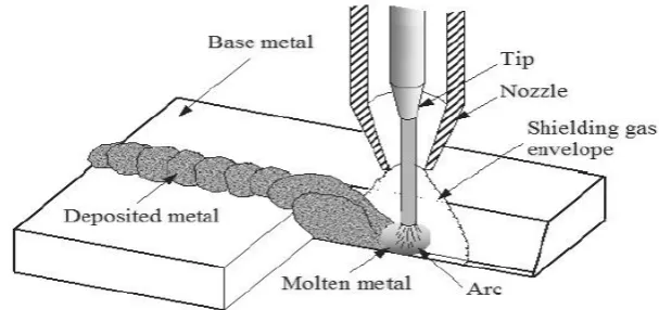
[image:21.595.187.491.343.486.2]Weglowski et al., (2008) indicate that the increasing of gas metal arc welding (GMAW) employed for fabrication industries (Figure 2.1). This process is versatile, since it can be applied for all position welding. It can easily be integrated into the robotized production canters. Furthermore, this process is used an externally supplied of shielding gas and without the application of a pressure. MIG welding refers to the use of an inert gas while metal active gas welding (MAG) involves the use of an active gas (i.e. carbon dioxide and oxygen). A variant of the GMAW process uses a tubular electrode filled with metallic powders to make up the bulk of the core materials (metal core electrode). Normally, the commercially important metals such as carbon steel, high-strength low alloy steel, stainless steel, aluminium, copper, titanium, and nickel alloys can be welded in all position with GMAW process by choosing appropriate shielding gas, electrode, and welding variables.
Figure 2.1: GMAW process (Weglowski et al., 2008).
2.2.2 Advantages of Gas Metal Arc Weld
7
2.2.3 Limitation of Gas Metal Arc Weld
The GMAW process, like any other welding process, has certain limitations that restrict its use. First, the welding equipment is more complex, usually more costly, and less. Then, GMAW process is more difficult to apply in hard-to-reach places because the welding gun is larger than a small holder and must be held close to the joint within 10 to 19 mm. Lastly, its shielding gas limits outdoor applications unless protective (Ferjutz and Davis, 1993).
2.2.4 Metal Transfer Modes
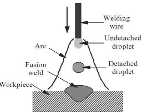
Weglowski et al., (2008) defines the metal transfer in GMAW as a process of transferring material of the welding wire in the form of molten liquid droplets to the work-piece (Figure 2.2). According to Ferjutz and Davis, (1993) the optimum transfer mode depends in part on the thickness of the base metal being welded. For example, very thin sections (in all positions) require the short-circuiting mode (with low current levels and appropriate settings of voltage and other operating parameters, including shielding gas composition). Thicker sections show best results with spray or streaming transfer. These transfer modes also produce high heat input, maximum penetration, and a high deposition rate.
8
intermittent arc extinguishment and re-ignition. It requires low heat input hence it is commonly used in welding thin sheets (Weglowski et al, 2008).
[image:23.595.202.437.420.607.2]During the mid 1960s, an alternative transfer technique of metal transfer that is pulse-spray metal transfer mode was invented. This mode of metal transfer able to overcomes the drawbacks of globular mode while achieving the benefits of spray transfer. This metal transfer mode is characterized by pulsing of current between low-level background current and high-level peak current. It provides stability by operates mostly in one drop per pulse to the arc. It also produces lesser distortions and fumes. Pulse-spray metal transfer mode able reduces the heat input to the base material and operates mostly in one drop per pulse which provides good stability to the arc. Furthermore, it operates with large diameter electrode wire for wider application ranges and reduces wire feeding problems in welding equipment and porosity incidence because of smaller surface area to volume ratio (Praveen and Yarlagadda, 2005). Variation of transfer mode for GMAW process was illustrated in the Table 2.1.
9
[image:24.595.230.419.54.199.2]Figure 2.3: Different modes of metal transfers in GMAW (a) globular, (b) spray, and (c) pulse (Weglowski et al., 2008).
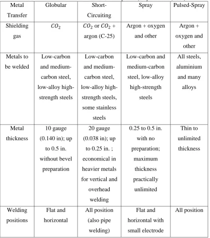
Table 2.1: Variation of transfer mode for GMAW process (Cary and Helzer, 2004). Metal
Transfer
Globular Short-Circuiting
Spray Pulsed-Spray
Shielding gas
𝐶𝑂2 𝐶𝑂2 or 𝐶𝑂2 + argon (C-25)
Argon + oxygen and other Argon + oxygen and other Metals to be welded Low-carbon and medium-carbon steel, low-alloy high-strength steels Low-carbon and medium-carbon steel, low-alloy high-strength steels, some stainless steels Low-carbon and medium-carbon steel, low-alloy high-strength steels All steels, aluminium and many alloys Metal thickness 10 gauge (0.140 in); up
to 0.5 in. without bevel
preparation
20 gauge (0.038 in); up
to 0.25 in. ; economical in heavier metals for vertical and
overhead welding
[image:24.595.108.534.280.763.2]