White Rose Research Online URL for this paper:
http://eprints.whiterose.ac.uk/78002/
Version: Published Version
Proceedings Paper:
Oliveira, André, Campos, Guilherme, Dias, Paulo et al. (4 more authors) (2013) Real-time
dynamic image-source implementation for auralisation. In: Proceedings of the 16th
International Conference on Digital Audio Effects. 16th International Conference on Digital
Audio Effects, 02-05 Sep 2013 , IRL , pp. 368-372.
Reuse
Items deposited in White Rose Research Online are protected by copyright, with all rights reserved unless
indicated otherwise. They may be downloaded and/or printed for private study, or other acts as permitted by
national copyright laws. The publisher or other rights holders may allow further reproduction and re-use of
the full text version. This is indicated by the licence information on the White Rose Research Online record
for the item.
Takedown
If you consider content in White Rose Research Online to be in breach of UK law, please notify us by
REAL-TIME DYNAMIC IMAGE-SOURCE IMPLEMENTATION FOR AURALISATION
André Oliveira
IEETA
1University of Aveiro
Aveiro, Portugal
[email protected]
Guilherme Campos
IEETA
1, DETI
2University of Aveiro
Aveiro, Portugal
[email protected]
Paulo Dias
IEETA
1, DETI
2University of Aveiro
Aveiro, Portugal
[email protected]
Damian Murphy
Audio Lab, Dept. of Electronics
University of York
York, UK
[email protected]
José Vieira
IEETA
1, DETI
2University of Aveiro
Aveiro, Portugal
[email protected]
Catarina Mendonça
Dept. of Psychology
Carl von Ossietzky University
Oldenburg, Germany
[email protected]
Jorge Santos
Dept. of Psychology
University of Minho
Braga, Portugal
[email protected]
ABSTRACT
This paper describes a software package for auralisation in inter-active virtual reality environments. Its purpose is to reproduce, in real time, the 3D soundfield within a virtual room where lis-tener and sound sources can be moved freely. Output sound is pre-sented binaurally using headphones. Auralisation is based on geo-metric acoustic models combined with head-related transfer func-tions (HRTFs): the direct sound and reflecfunc-tions from each source are computed dynamically by the image-source method. Direc-tional cues are obtained by filtering these incoming sounds by the HRTFs corresponding to their propagation directions relative to the listener, computed on the basis of the information provided by a head-tracking device. Two interactive real-time applications were developed to demonstrate the operation of this software pack-age. Both provide a visual representation of listener (position and head orientation) and sources (including image sources). One fo-cusses on the auralisation-visualisation synchrony and the other on the dynamic calculation of reflection paths. Computational perfor-mance results of the auralisation system are presented.
1. INTRODUCTION
Virtual Reality (VR) systems find application, and are gradually becoming indispensable tools, in areas like architecture, aviation, industrial automation, entertainment or experimental psychology, to name only a few. Research and development in VR have tradi-tionally favoured the visual side of VR [1]. However, a convincing feeling of immersion demands agreement between what one sees
1Institute of Electronics and Telematics Engineering of Aveiro. 2Department of Electronics, Telecommunications and Informatics.
(visualisation) and what one hears (auralisation) [2]. It is there-fore essential to develop the audio side of VR models, and much work is being done in this area [3]. The auralisation system pre-sented in this paper follows some of the footsteps of existing au-ralisation systems such as DIVA [4], RAVEN [5] and SoundScape Renderer [6], with a focus on real-time performance and dynamic environments.
The process of auralisation of a VR environment consists in ar-tificially recreating the sound stimuli that would reach the two ears (binaural sound) of a listener effectively present in that environ-ment. Sets of head-related impulse responses (HRIR) or, equiv-alently, their corresponding Fourier transforms (known as head-related transfer functions - HRTF) are used for that purpose [7]. An HRIR set contains the responses, measured at each ear, to Dirac pulses generated at points distributed over a spherical surface cen-tered at the listener’s head. These responses capture the main cues used by the human brain to locate a sound source, namely the in-teraural time difference (ITD) and inin-teraural intensity difference (IID), as well as spectral cues dependent upon the anatomy of the listener’s pinnae, head and torso. The binaural stimuli generated by a source on a given direction can be obtained by convolving an anechoic recording of the source with the HRIR corresponding to that direction.
In order to achieve convincing auralisation using geometric models, one must take into account not only the direct sounds (i.e. arriving directly from the sources) but also the reflections off the boundaries of the room (which can be regarded as direct sounds from image-sources placed beyond those boundaries). The main challenge is to accomplish this in real time, as the computa-tion time grows exponentially with the number of boundaries and sources.
implemented software. It processes the anechoic sound emmited by a source to generate the corresponding binaural stimuli, based upon the geometric model of the room, source and listener posi-tions, and listener head orientation.
attenuate resampler HRTF
previous HRTF
cross fade delay and
sound sound
distance velocity azimuth elevation geometric acoustic processing
modelroom positionsource positionlistener orientationlistener
binaural anechoic
Auralisation
Figure 1: Diagram of the auralisation block. Binaural sound is generated by processing the anechoic sound of the source accord-ing to the specified room model, source and listener positions, and listener head orientation dynamic parameters.
Two sub-blocks can be distinguished: geometric acoustic pro-cessing (dashed lines) and audio propro-cessing (solid lines).
2. GEOMETRIC ACOUSTIC PROCESSING
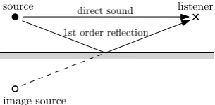
The geometric acoustic processing sub-block is responsible for up-dating the distance, velocity, azimuth and elevation of each sound source relative to the listener. This includes image-sources, to ac-count for room boundary reflections up to a given order, computed using the image-source method [8]. Each room boundary surface defines image-sources (i.e. placed symmetrically relative to that surface plane) of the sources present in the room. The sound re-flected off the surface can be generated as if it had been emmited directly by the image-source. This is illustrated in Figure 2. Higher order image-sources are calculated by applying this image-source method recursively, from the previous order image-sources.
source direct sound
1st order reflection
image-source
[image:3.595.51.288.142.256.2]listener
Figure 2:Image-source method. Reflection paths are calculated by defining image-sources symmetric to the sound sources, relative to the surfaces.
The geometry of the room can be loaded from standard 3D model files, such as Wavefront .obj files, and the auralisation soft-ware supports arbitrary room shapes, convex or concave.
In a convex room (a closed space where the dihedral angles of all adjacent surfaces do not exceed 180 degrees), all image-sources are “visible,” i.e. represent sounds that reach the listener and must be auralised. However, in a concave (non-convex) space, the sound from an image-source may not exist in reality, either because its presumed path does not actually cross the surface that generated
that image-source or because it is obstructed by other surfaces; the image-source is said to be “invisible.”
The geometric acoustic processing block handles both convex and concave rooms by internally representing the room surfaces as n-point planar polygons (convex or concave) and performing visibility checks on each image-source. If any of the polygons in-tersect the hypothetical sound path being checked, then that sound path is not visible, and therefore is not auralised.
The visibility checks are performed using a point-in-polygon algorithm [9] for the general case of concave polygons. For this case, the algorithm is slightly more complex than if the surfaces were defined by convex polygons (typically triangles), but this way much fewer polygons need to be tested (a surface defined by a sin-gle concave polygon would otherwise need to be defined by at least two triangles). On the other hand, using only convex polygons would allow the use of binary search partitioning algorithms [10] that could potentially reduce the visibility check complexity from exponential,O(NP)
, to logarithmic,O(NlogP). This possibil-ity will be explored in future implementations.
[image:3.595.310.545.359.415.2]Figure 3 shows the reflections calculated by the geometric acoustic processing block for a concave room and where the visi-bility checks were essential in properly handling the inner surfaces. The reader is referred to the following link where a video showing these calculations being performed in real-time while the source and listener move freely is available [11].
Figure 3: Screenshots of the calculated reflections for a concave room: 1st, 2nd and 3rd order reflections (left) and all reflections up to the 8th order (right).
3. AUDIO PROCESSING
The audio processing blocks are responsible for generating the bin-aural contribution of every source (including image sources). The processing is executed independently for each source, since each one has its own anechoic sound and all the required parameters (distance, velocity, azimuth and elevation relative to the listener) are provided by the geometric processing sub-block (see Figure 1).
3.1. Sound propagation delay and attenuation
The distance,d[n](m), between source and listener is used by the delay and attenuate block in Figure 1 to simulate the air propa-gation delay, in samples, and attenuation, in dB. Letvsound be the speed of sound in air (≈343.2m/s) andfsthe sampling
fre-quency (Hz) of the anechoic signal of the source; then,
delay[n] = d[n]
vsoundfs
The sound signal is attenuated by 6dB per doubling of the trav-elled distance; takingdhrtfto be the distance at which the HRTFs were recorded, then
attenuation[n] = 20 log10 d[n]
[image:3.595.93.246.506.581.2]3.2. Doppler Effect
The velocity of the source relative to the listener,v[n](m), is used to simulate the Doppler effect [12]. The resampler block in Fig-ure 1 performs the task of resampling the original signal from its original sampling frequencyfs to the apparent frequencyf′
s[n]
corresponding to the relative velocityv[n]. It is assumed that both source and listener travel at velocities well below the speed of sound propagation,vsound.
f′
s[n]≈
(
1 + v[n]
vsound
)
fs
The implemented resampling algorithm uses linear interpola-tion (first-order hold), which offers a good compromise between low harmonic distortion and computation time.
3.3. HRTF Processing
The source azimuth and elevation relative to the user, calculated by the geometric processing block, are the parameters used by the HRTF blocks in Figure 1 to determine the appropriate pair of HRTFs to extract from the HRTF set stored in memory.
The MIT KEMAR HRTF compact set [13] was used for the evaluation of the system, but the implementation supports the use of other HRTF sets, non-individualised and individualised [14].
The anechoic source sound is then filtered by the selected HRTF pair using the overlap-add method [15], which carries out the filter-ing operations in the frequeny domain, with a computational cost
O(N+Nlog2N), as opposed to the time-domain HRIR
convolu-tionO(N2
). The required discrete Fourier transform calculations (FFT and IFFT) are performed using the FFTW library [16].
3.4. Real-Time Interaction and Final Output
One of the main goals in the design of this auralisation system is that it should provide real-time user interaction, reacting seam-lessly to every movement of the listener and sound sources, with no related impact on the rendering of the final audio output.
The source and listener positions and the listener orientation parameters in Figure 1 are typically updated in large discrete steps and at low rates, when compared to the quantisation steps and sampling rates of the anechoic sounds. For example, the posi-tions might be given by a camera filming the human listener at 60 frames per second, or the orientation might be given by a head-tracking sensor attached to the human listener at 150Hz, while sounds might have a sampling rate of 44100Hz. If these param-eters were to be used directly by the audio processing blocks, the resulting audio would reflect those steps, which would result in some form of audible distortion (clicks, pops, wow, flutter).
The audio processing block handles the movement of the lis-tener and sources by upsampling the distance and velocity param-eters in Figure 1 to the audio sampling rate, followed by low-pass filtering. Thedelay and attenuate block and the resampler block, which operate in the time domain, then process each audio sample using the corresponding upsampled and slowly-changing parame-ter values, this way outputing distortion-free audio.
The HRTF block, on the other hand, is limited not by the az-imuth and elevation parameters, but by the HRTF datasets, which only contain measurements at discrete spatial intervals, namely, in the case of the MIT KEMAR compact set, 10 degrees in eleva-tion and 5 degrees or more in azimuth, and by the fact that the HRTF processing is performed in the frequency domain, in blocks
of 128 samples, the length of the HRIRs of the MIT KEMAR set. The blockscrossfade and previous HRTF in Figure 1 are then in-dispensable to eliminate the discontinuities that would otherwise inevitably occur in the output binaural signal whenever a transi-tion from one HRTF to another HRTF occurred [17].
The audio processing described above is replicated for each sound source and corresponding image-source. The resulting bin-aural contributions are all added together to yield the final binbin-aural output sound of the auralised model.
4. RESULTS
The main result of the work here described is a software pack-age for real-time, interactive auralisation of virtual reality environ-ments. It handles dynamic listener position and head orientation, multiple sound sources whose positions can equally be changed and takes into account both direct sound and wall reflections, based on a geometric model of the virtual room, convex or concave, which can be loaded from standard 3D-model files. It is imple-mented in C, in the form of a library, therefore it can be easily used in many different applications and platforms.
Computational performance tests were carried out on the ge-ometric acoustic processing block and on the audio processing block separately to evaluate the real-time capabilities of the soft-ware. The tests were executed on an ordinary desktop computer, with a dual-core processor at 2.5 GHz. The audio was processed using a reference frame size of 1024 16-bit samples at 44.1kHz, which corresponds to a 23.22ms period, the time available for all the processing and therefore the limit for real-time performance.
Table 1 shows the processing times of the geometric acoustic processing block for a concave room with 10 surfaces, for increas-ing number of reflections. As expected, the number of visibil-ity checks, and therefore the processing time, grows exponentially with the reflection order. For this hardware and room model, real-time performance is possible up to the 5th reflection order.
Table 1:Geometric acoustic processing times for a concave room with 10 surfaces (8 walls, floor and ceiling).
Reflection Visibility Sound Paths Processing Order Checks Discovered Time (ms)
0 10 1 0.006
1 159 7 0.011
2 1,064 23 0.047
3 6,994 52 0.289
4 54,749 96 2.315
5 477,034 162 20.454
6 4,377,747 256 190.136 7 41,334,476 374 1809.742
Table 2 shows the processing times of the audio processing block. This processing time grows linearly with the number of sound sources (real sources and image-sources). For this hard-ware, it is possible to auralise up to 133 sound sources in real-time (134 sources exceeded the 23.22ms real-time performace limit and thus resulted in audio hardware buffer underrun).
Table 2:Total processing times of the audio processing blocks for increasing number of rendered sound sources, up to the real-time performance limit of 23.22ms.
Sound Sources Processing Time (ms)
10 1.69
35 5.64
63 10.35
133 22.18
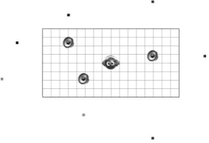
[image:5.595.89.238.289.391.2]virtual room, as well as the position and head orientation of a vir-tual listener (representing himself), with a head-tracking device, and auralise the resulting scene in real time (using headphones). A screenshot of this application is presented in Figure 4.
Figure 4:Demonstration application. Real-time auralisation of in-teractive listener, three sound sources and 1st order image-sources in a virtual room.
In the example shown, the room has a 16m x 8m floor plan and there are three sound sources, whose corresponding image-sources are also visualised, indicated by the outer dots, when reflections are enabled. The sound sources, as well as the virtual listener, can be moved by simple click-and-drag mouse operations; the image-source positions are automatically updated accordingly, as calcu-lated by the geometric acoustic processing block.
The application also receives data from an inertial head tracker with 3 degrees of freeedom (3DOF) attached to the headphones worn by the user. The acquired data is passed on to the auralisa-tion library and this responds in real time, i.e. the ear stimuli are constantly updated according to the head orientation of the listener. The reader is referred to the following link where a video of this application can be seen, with moving sources and listener, head-tracking, with and without reflections, and the auralised au-dio can be heard [18].
5. FUTURE WORK
The auralisation software here presented can already constitute a very useful tool for psychoacoustics research (e.g. on the per-ception of source distance, localisation and motion). It must, of course, be validated (through perceptual tests) as to its degree of realism.
The model supports both convex and concave room geome-tries. The early reflections provide good cues on the geometry of the room, but the localisation and spatial impression will certainly
improve with the inclusion of more higher-order reflections. This involves the implementation of an artificial method of simulating the reverberation tail, as the computation time of the image-source method grows exponentially with the number of reflections.
The processing required for a given sound source is indepen-dent of the other sources. This means the implementation could be adapted to take full advantage of the parallel processing capabili-ties of modern processors. The use of GPUs is also envisaged.
6. ACKNOWLEDGMENTS
This work was funded by the Portuguese Government through FCT (Fundação para a Ciência e a Tecnologia) as part of the project AcousticAVE: Auralisation Models and Applications for Virtual Reality Environments (PTDC/EEA-ELC/112137/2009).
7. REFERENCES
[1] C. Verron, M. Aramaki, R. Kronland-Martinet, and G. Pal-lone, “A 3D Immersive Synthesizer for Environmental Sounds,” IEEE Transactions on Audio, Speech, and Lan-guage Processing, vol. 18, no. 6, pp. 1550–1561, 2010.
[2] Khoa-Van Nguyen, Clara Suied, Isabelle Viaud-Delmon, and Olivier Warusfel, “Spatial audition in a static virtual envi-ronment: the role of auditory-visual interaction,” J. Virtual Reality and Broadcasting, vol. 6, no. 5, 2009.
[3] Thomas Funkhouser, Nicolas Tsingos, and Jean-Marc Jot, “Survey of methods for modeling sound propagation in in-teractive virtual environment systems,” Presence, 2004.
[4] Tapio Lokki and Lauri Savioja, “The DIVA auralization sys-tem,” inACM Siggraph Campfire: Acoustic Rendering for Virtual Environmens, Snowbird, UT, 2001.
[5] Dirk Schröder and Michael Vorländer, “RAVEN: a real-time framework for the auralization of interactive virtual environ-ments,”Forum Acusticum, 2011.
[6] Matthias Geier, Jens Ahrens, and Sascha Spors, “The Sound-Scape Renderer: A unified spatial audio reproduction frame-work for arbitrary rendering methods,” inProceedings of the 124th AES Convention, May 2008.
[7] Corey Cheng and Gregory Wakefield, “Introduction to head-related transfer functions (HRTFs): Representation of HRTFs in time, frequency and space,” J. Audio Eng. Soc. (AES), vol. 49, no. 4, 2001.
[8] Lauri Savioja, Jyri Huopaniemi, Tapio Lokki, and Riitta Väänänen, “Creating interactive virtual acoustic environ-ments,”J. Audio Eng. Soc. (AES), vol. 47, no. 9, 1999.
[9] Dirk Schröder, Physically Based Real-Time Auralization of Interactive Virtual Environments, Ph.D. thesis, RWTH Aachen University, 2011.
[10] Dirk Schröder and Tobias Lentz, “Real-time processing of image sources using binary space partitioning,”J. Audio Eng. Soc. (AES), vol. 54, no. 7, 2006.
[12] Joe Rosen and Lisa Gothard,Encyclopedia of Physical Sci-ence, Volume I, Infobase Publishing, 2009.
[13] Bill Gardner and Keith Martin, “HRTF measure-ments of a KEMAR dummy-head microphone,” 1994, http://sound.media.mit.edu/resources/KEMAR.html.
[14] Catarina Mendonça, Guilherme Campos, Paulo Dias, José Vieira, João Ferreira, and Jorge Santos, “On the im-provement of localization accuracy with non-individualized HRTF-based sounds,”J. Audio Eng. Soc. (AES), vol. 60, no. 10, 2012.
[15] Udo Zölzer, Digital Audio Signal Processing, Wiley-Blackwell, 2008.
[16] Matteo Frigo and Steven Johnson, “The design and imple-mentation of FFTW3,”Proceedings of the IEEE, vol. 93, no. 2, pp. 216–231, 2005.
[17] Tom Barker, Guilherme Campos, Paulo Dias, José Vieira, Catarina Mendonça, and Jorge Santos, “Real-time auralisa-tion system for virtual microphone posiauralisa-tioning,” 15th Inter-nation Conference on Digital Audio Effects, 2012.