Electron beam manipulation, injection and acceleration in plasma wakefield accelerators
by optically generated plasma density spikes
G. Wittiga, O. Kargera, A. Knetscha, Y. Xib, A. Dengb, J. B. Rosenzweigb, D.L. Bruhwilerc,d, J. Smithe, Z.-M. Shengf, D.A. Jaroszynskif, G.G. Manahanf, B. Hiddinga,f
aInstitute of Experimental Physics, University of Hamburg, 22761 Hamburg, Germany bParticle Beam Physics Laboratory, UCLA, Los Angeles, California 90095, USA
cRadiaSoft LLC, Boulder, Colorado 80304, USA dRadiaBeam Technologies LLC, USA eTech-X UK Ltd, Daresbury, Cheshire WA4 4FS, UK
fPhysics Department, SUPA, University of Strathclyde, Glasgow G4 0NG, UK
Abstract
We discuss considerations regarding a novel and robust scheme for optically triggered electron bunch generation in plasma wakefield accelerators [1]. In this technique, a transversely propagating focused laser pulse ignites a quasi-stationary plasma column before the arrival of the plasma wake. This localized plasma density enhancement or optical “plasma torch” distorts the blowout during the arrival of the electron drive bunch and modifies the electron trajectories, resulting in a controlled injection. By changing the laser pulse parameters such as beam waist and intensity, and by moving the focal point of the laser pulse, the shape of the plasma torch can be tuned easily. The proposed method is much more flexible and faster in generating gas density transitions when compared to hydrodynamics-based methods, and it accommodates experimentalists needs as it is a purely optical process and straightforward to implement.
Keywords:
PACS:52.40.Mj, 29.27.Ac, 52.50.Dg, 52.65.
1. Introduction
1
The dynamics of electron injection in plasma wakefield
ac-2
celerators is a main focus of research in the plasma
acceler-3
ator community, both experimentally and theoretically. The
4
quality of the extracted witness bunches strongly depends on
5
the process of trapping in the plasma wave. Several injection
6
techniques have been proposed and have partially been
demon-7
strated in LWFA as well as in PWFA such as [2, 3, 4, 5, 6, 7, 8,
8
9, 10, 11, 12, 13, 14, 15, 16] as well as in the form of hybrid
Tro-9
jan Horse-type methods [17, 18, 19, 20, 21, 22]. The ”plasma
10
torch” technique, as recently introduced in [1], is a flexible and
11
simple technique for injection and trapping of electron bunches
12
into the accelerating phase of plasma wakefield accelerators
13
(predominantly, for PWFA, but potentially also for LWFA) and
14
exploits a combination of optically generated density
transi-15
tions as well as ionization injection and localized blowout
am-16
plification effects.
17
Here, a focused laser pulse propagating perpendicularly (or at
18
an arbitrary angle) to the driver beam axis (z) is used to ionize
19
homogeneously distributed gas media in advance of the drive
20
beam arrival, leading to a sharply spiked plasma density
pro-21
file where the ionization threshold is exceeded by the electric
22
field of the laser pulse. We refer to this region of optically
23
excited, shapable plasma density volume as ”plasma torch.”
24
This optical torch also has potential application in shaping of
25
plasma cell boundaries and in the realization of ultrafast
elec-26
tron bunch kickers [23]. The density elevation may be created
27
on fs to many ps and up to ns time scale before the arrival of
28
the electron-driven wakefield, using a modestly intense laser
29
pulse, e.g. at theI ∼1015W/cm2 level in case of Ti:Sapphire
30
laser pulses. The shape of the density profile is tunable by
di-31
rectly controlling parameters such as the energy and intensity
32
profile of the laser pulse. Furthermore, this method does not
33
require hydrodynamic expansion after optical excitation by a
34
near-relativistic intense laser pulse, which is the prerequisite
35
of the laser-driven (LWFA) scheme as discussed in Ref. [24,
36
5, 25]. In the plasma torch scheme, the plasma density shape
37
does not rely on motion of ions and is a direct imprint of the
38
applied laser profile and intensity, therefore very steep density
39
transitions can be created on fs time scales. For example also
40
between driver-witness electron bunch pairs even if they have
41
few micrometer-scale distances, which may be useful to
sep-42
arate the drive beam from the witness. The plasma density
43
spikes generated by the torch have ultrafast (fs-scale) rise times,
44
and decay times of the order of the recombination timescale.
45
The electron beam drives the plasma wave which is based on
46
a low ionization threshold (LIT) gas species, while another (or
47
more) gas component, which needs a higher ionization
thresh-48
old (HIT), is left unaffected.
49
Both using a laser pulse at LIT or HIT ionization threshold
in-50
tensities can be used to manipulate the beam-plasma
interac-51
tion, including triggering injection of electrons, but the purely
LIT-based plasma torch is limited to self-ionized PWFA cases
53
because in the preionized cases the LIT medium is preionized
54
per definition and the plasma torch laser does not make any
dif-55
ference at these intensities unless it additionally ionizes the HIT
56
level.
57
2. Trapping and acceleration of electron bunches for diff
er-58
ent plasma compositions and laser intensities
59
Three possible scenarios of electron bunch trapping via the
60
plasma torch scheme, supported by three dimensional
particle-61
in-cell VSim/VORPAL[26] simulations, are considered. The
62
plasma torch approach requires – as all PWFA schemes – an
63
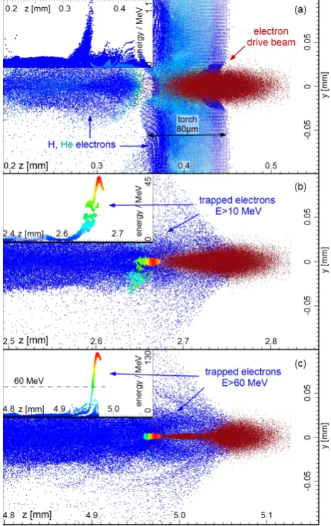
electron beam that can create a high-gradient plasma wake to
64
trap electrons, while its electric fields must not ionize the HIT
65
component. This is experimentally possible using a large range
66
of electron beams, including those generated in LWFA stages.
67
Here we use a FACET-class electron beam [27], having the
fol-68
lowing parameters: charge Q = 3 nC, energy E = 23 GeV,
69
energy spread∆E/E =2 %, bunch lengthσz =27µm,
trans-70
verse sizeσr = 8.5 µm, and normalized emittancen = 2.25
71
mm-mrad. A mixture of hydrogen and helium is implemented
72
as the plasma source, where hydrogen with its low ionization
73
energy is the LIT component and helium is the HIT
compo-74
nent. Using the formula for the tunneling ADK rates [28], a
75
peak field in the range of∼90 GV/m is required to quickly
ion-76
ize helium, which is hardly achievable even by a FACET-class
77
electron beam. Therefore He will generally stay in the neutral
78
state as long as the plasma torch laser does not ionize it
pur-79
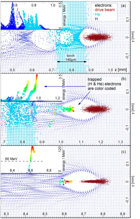
posefully
80
The use of a hydrogen/helium gas mixture allows for three
qual-81
itatively different possible main scenarios: (i) initially hydrogen
82
and helium are in the neutral state, and the electron beam driver
83
ionizes hydrogen on axis, while the plasma torch laser pulse
84
does pre-ionize hydrogen locally in front of the drive beam.
He-85
lium is left in neutral state throughout the process; (ii) same as
86
case (i), i.e. no general preionization but self-ionization by the
87
drive bunch, but the torch laser ionizes both hydrogen and
he-88
lium locally; and (iii) hydrogen is completely preionized, for
89
example by an on-axis laser pulse (focused by a lens, an
axi-90
con or advanced diffractive optics), and the torch laser ionizes
91
additional helium locally in the pathway of the drive beam. It
92
shall be noted that by using diffractive optics, it may be possible
93
to adjust the on-axis intensity profile of the preionization laser
94
pulse such that an intensity spike is generated which then acts to
95
a similar effect as an independently tunable plasma torch laser,
96
albeit without its flexibility. In all selected simulations, a laser
97
pulse propagates perpendicular to the electron beam and
gen-98
erates the plasma torch approximately 1 ps before the
electron-99
beam driven plasma wave arrives – this is to save computational
100
costs by keeping the simulation window sufficiently small. In
101
reality, it does not matter much if the plasma torch laser pulse
102
arrives few hundred femtoseconds or many picoseconds before
103
the electron beam driven plasma wave, as long as neither
re-104
combination effects nor ion and hydrodynamic motion sets in.
105
This is advantageous because it means that the requirements
106
put on the synchronization between electron beam driver and
107
plasma torch laser pulse can be easily met. In the considered
108
cases, the plasma torch laser pulse is based on a Ti:sapphire
109
laser system, with central wavelength ofλ = 800 nm and a
110
pulse duration (FWHM) ofτ =64 fs. The delay between the
111
torch laser and the electron driver was carefully chosen in the
112
simulation such that the optical plasma torch is allowed to build
113
up before the arrival of the electron beam, while at the same
114
time the simulation box window length is minimized.
115
All given densities are free electron densities (when ionized),
116
and atomic densities (when in neutral state), because only single
117
ionization occurs both are equal. The actual parameters for the
118
three cases are chosen based on analytical calculations of
ion-119
ization levels and yields. All simulations of electron trapping
120
triggered by optical plasma torches are compared with
simu-121
lations without a plasma torch to confirm that the trapping is
122
solely due to the plasma torch density perturbation. The
combi-123
nations of laser waistw0and dimensionless amplitudea0have
124
been chosen in all scenarios such that the torch width is equal
125
or greater than the plasma wavelengthλp = 2πc
p
0me/nee2
126
within the plasma torch, in order to allow for the plasma wave
127
to interact at increased density at least over oneλp(mebeing the
128
electron mass,cspeed of light in vacuum,eelectron charge,ne
129
the electron density, and0 the vacuum permittivity). On the
130
other hand, a compact torch allows for a rapid density
transi-131
tion. It is known that the downramp length should be shorter
132
than the plasma skin depthk−p1=c/ωp[29] for electron bunch
133
injection in PWFA. This criterion is fulfilled in each case.
134
Figure 1 shows the injection process of the first scenario, where
135
neutral hydrogen is used and the torch laser is only ionizing
hy-136
drogen locally in the drive beam’s path. In this case, the drive
137
beam has to self-ionize hydrogen outside of the plasma torch
re-138
gion in order to generate a plasma, which is only possible near
139
the center of the bunch, where the peak fields are high enough
140
to exceed the hydrogen ionization threshold. Consequently,
fur-141
ther ahead in the drive bunch there is no plasma, because the
142
electric fields are much lower due to the smaller density, and
143
outside the plasma torch region, the front part of the drive beam
144
is simply unused.
145
The effective ionization front determines the beginning of the
146
plasma wave, which is shifted rapidly to the front of the drive
147
beam when entering the preionized region produced by the torch
148
laser. Additionally, during the passage of the torch, the
wake-149
field is significantly amplified, as now more drive beam current
150
is contributing to the excitation. When the plasma torch volume
151
is left and the drive beam exits the locally preionized hydrogen
152
plasma region, the blowout shifts back again, since hydrogen
153
once more needs to be self ionized by the drive beam. This
154
snapping back of the plasma wave results in trapping of
elec-155
trons very effectively. It is remarkable to note that neither the
156
hydrogen gas density nor the plasma wavelength are changed
157
during this process, which is a fundamental difference to gas
158
density downramp injection.
159
Afterz ≈5 mm of propagation (≈4.6 mm behind the torch),
160
the generated witness bunch with energies exceeding 100 MeV
161
has normalized emittance ofn = 3.5 mm mrad, Q =34 pC,
162
mean energy ofE =160 MeV, energy spreadσE/E =12.5%;
and a peak current ofIpeak =2.0 kA. Also evident in Figure 1
Figure 1: Optical plasma torch injection for scenario (i), using a hydrogen den-sity ofnH = 4×1017cm−3 (hydrogen electrons are visualized as blue dots, y,z are the torch laser, and drive beam propagation axes). The plasma torch is generated in the path of the drive beam (red dots), and crossed in (a), leading to blowout amplification and injection. Applying a laser pulse withw0=35µm,
anda0=0.015 a torch of approximately 60µm width is created. The injected
hydrogen electrons (color coded spheres) are shown in (b)≈2.2 mm after the
torch, and in (c) after z≈4.6 mm of acceleration, where maximum energies of
E≈194 MeV are reached.
164
(c) is the lensing effect of the plasma on the drive bunch which
165
supports the wake’s acceleration field strength.
166
In Figure 2 the second scenario is illustrated, similar to
Fig-167
ure 1. Here, the torch laser intensity is increased toa0 =0.03
168
in order to allow the local laser ionization of both helium and
169
hydrogen. Obtained witness bunch parameters at z ≈ 5 mm,
170
counting electrons with energies exceeding 60 MeV are:
nor-171
malized emittance n = 1.0 mm mrad; charge Q = 274 pC;
172
mean energyE=118 MeV; energy spreadσE/E=12.0%; and
173
a peak current at Ipeak =11.1 kA. Electrons of both elements
174
are trapped and form the witness bunch. The total amount
175
of trapped charge can be independently tuned via the helium
176
gas density (up to beam loading levels) in contrast to scenario
177
(i). In fact, here the accelerating filed is lowered, compared
178
to case (i), due to the much higher trapped charge and
conse-179
quently the energy gain is decreased. In Figure 3 the last
sce-Figure 2: Optical plasma torch injection in scenario (ii), where a hydrogen den-sity ofnH =4×1017cm−3, and helium density ofnHe =3×1017cm−3was
used. Same as in scenario (i), but in addition the plasma torch also comprises helium electrons (light blue spheres), which leads to a double trapezoidal den-sity shape. The plasma torch is generated in the path of the drive beam, where the laser intensity has been adjusted to ionize helium as well. A laser pulse
w0 = 35µm anda0 =0.03 is used. In (a) the torch is crossed, leading to
blowout amplification and injection. The injected electrons are shown in (b)
≈2.2 mm behind the torch, and (c) after z≈4.6 mm of acceleration, where the
maximum energy of E≈128 MeV is reached.
180
nario is illustrated, which applies preionized hydrogen (LIT).
181
Using the same plasma densities as in cases (i) and (ii),
un-182
controlled electron injection would occur due to strong
elec-183
tric fields of the blowout [10, 21, 15] that would partly ionize
184
and trap helium. To mitigate this effect, reduced gas densities
185
for hydrogen and helium are used: nH = 5×1016 cm−3, and
186
nHe = 1×1017 cm−3, since the longitudinal fields are
propor-187
tional to the ambient plasma density Ez ∝ n1/2. The
reduc-188
tion of the plasma density decreases the electric field, avoiding
189
dark current generation at the rear of the blowout. It shall be
190
noted that alternatively, one may also use a weaker driver bunch
191
but elevated hydrogen densities. This would generate smaller
192
blowouts, but nevertheless small enough wakefields as required
193
to avoid He ionization or, more importantly, dark current
[image:3.595.45.278.106.480.2]ping. In this scenario, electron bunch injection and trapping is
195
because of the extension of the plasma wavelength when
leav-196
ing the plasma torch, resulting in electron injection due to the
197
plasma downramp at the end: a process similar to standard gas
198
density downramp injection. Obtained witness bunch
param-199
eters after≈ 7.7 mm of acceleration, counting electrons with
200
energies exceeding 60 MeV are: normalized emittancen=1.8
201
mm mrad; chargeQ=1.9 nC; mean energy atE =106 MeV;
202
energy spreadσE/E=12.6%; and a peak current atIpeak=22
203
[image:4.595.315.549.188.305.2]kA.
Figure 3: Optical plasma torch injection in scenario (iii) with preionized hydro-gen. At gas densities ofnH=5×1016cm−3, andnHe=1×1017cm−3, a pro-nounced blowout is generated. The tunable helium electron torch (a) downramp leads to dark-current free witness bunch formation (b) and allows for massive charge at substantially beam-loaded levels (c). A laser pulse withw0=100µm
anda0=0.033 is used to ignite the optical plasma torch (y,z are the torch laser,
and beam propagation axes, respectively).
204
3. Experimental realization of the optical plasma torch
205
The technique presented in this paper can be experimentally
206
realized for example in 90◦geometry, as illustrated in Figure 4
207
and as used for the presented simulations. Spatial alignment of
208
the order of the torch laser beam waist or the plasma blowout
209
width, respectively, is comparably easily achieved. Temporal
210
synchronization between the electron driver beam and plasma
211
torch laser pulses, as mentioned above, is also easily satisfiable.
212
An energy of the plasma torch laser of the order of a mJ at pulse
213
durations of a few tens of fs can be sufficient, since such pulses
214
can be focused to the intensities of 1014−15W/cm2at the
interac-215
tion point. This is the intensity level for ionization of either
hy-216
drogen (case i) or hydrogen and helium (case ii and iii). For
sce-Figure 4: Experimental setup: An electron beam driver and one (scenario i, and ii) or two (scenario iii) moderately synchronized laser pulses interact in an underdense two component gas mixture such as hydrogen and helium. One laser pulse is focused to intensities of theI≈1014−15W/cm2level in order to
generate the localized hydrogen/helium plasma torch in the path of the electron beam driven blowout. In contrast to the self-ionized scenario (i) and (ii), for scenario (iii) another, high-energy fraction of the laser pulse is used to preionize the hydrogen.
217
nario (iii), an additional laser arm is required which is needed to
218
produce a preionized hydrogen plasma channel around the
elec-219
tron beam axis (or any other means of selective preionization).
220
This general preionization laser needs much higher energy, but
221
as it will be much softer focused than the plasma torch laser (in
222
case of Gaussian focusing optics), or by diffractive optics, will
223
reach much lower peak intensities than the plasma torch laser.
224
It shall be noted that while the above has been simulated and
225
discussed with respect to electron beam driven PWFA, it could
226
also be used for LWFA. This is not easy for Ti:Sapphire drive
227
pulses, as the high intensities ofI >1018W/cm2which are
re-228
quired in order to excite a strong enough bubble, will ionize
229
most media and many higher level ionization states even in the
230
rising slope of the laser pulse driver. However, longer
wave-231
length laser systems such as in the mid-IR and at CO2
wave-232
length are showing much progress, and may be intense enough
233
to drive strong wakefields in the future. Such laser pulses, due
234
to their much lower peak electric fieldsE=(2πmec2/e)a/λ(λ
235
being the laser wavelength,athe normalized amplitude of the
236
laser vector potential), may then allow for plasma density spikes
237
to be generated by short wavelength torch lasers. For example
238
frequency-doubled or tripled Ti:Sapphire laser pulses [19], or
239
even higher harmonics, as the peak electric fields in such laser
240
pulses may be much higher when compared to the drive laser
241
pulse while at the same time having much lower ponderomotive
242
forceFp' −mec2∆a2/2 [30, 31].
[image:4.595.45.286.209.584.2]4. Summary
245
We have discussed a fully optically-steered method to
gen-246
erate tunable plasma density transitions. The torch width was
247
chosen to exceed at least one plasma wavelength in order to
al-248
low the blowout to close within the torch volume. This defines
249
the ability to trap electrons, e.g. for high torch densities the
250
plasma wavelength within the torch is shorter, allowing for a
251
smaller torch width. Different scenarios have been examined:
252
In scenario (i) injection occurs entirely due to the forward and
253
backward shifting of the plasma cavity, due to the jumping
ion-254
ization front position and amplification of the wake. In scenario
255
(iii), where preionized hydrogen is used, the front of the
wake-256
field does not change with respect to the electron beam driver.
257
Here electron injection occurs due to distortion of the plasma
258
wavelength, which is similar to conventional downramp
injec-259
tion. Scenario (ii) is a mixture of both, shifting the front of the
260
wakefield combined with a change in the plasma wavelength.
261
In the optical plasma torch technique a large range of field
262
strengths are covered by the accelerating electrons, which
re-263
sults in a rather large energy spread. However, by using a
264
second component (scenario ii and iii) the amount of trapped
265
charge and the bunch length can be controlled, as well as the
266
trapping position. Therefore beam loading can be utilized, e.g.
267
by adjusting the shape of the downramp, to lower the energy
268
spread along with the possibility to trap very short bunches in
269
the very rear of the blowout, leaving space for optimization of
270
this technique. Additionally different laser profiles and
intensi-271
ties can be applied to create diverse plasma profiles and ramp
272
lengths, to tune the current profile and length of the witness
273
bunch and to further optimize the bunch quality. Asymmetric
274
plasma torch profiles and multiple plasma torches may allow
275
for further enhanced flexibility.
276
[1] G. Wittig, O. Karger, A. Knetsch, Y. Xi, A. Deng, J. B. Rosenzweig, D. L.
277
Bruhwiler, J. Smith, G. G. Manahan, Z.-M. Sheng, D. A. Jaroszynski,
278
B. Hidding, Optical plasma torch electron bunch generation in plasma
279
wakefield accelerators, Phys. Rev. ST Accel. Beams 18 (2015) 081304,
280
doi:\bibinfo{doi}{10.1103/PhysRevSTAB.18.081304}, URL http://
281
link.aps.org/doi/10.1103/PhysRevSTAB.18.081304.
282
[2] S. Bulanov, N. Naumova, F. Pegoraro, J. Sakai, Particle injection into
283
the wave acceleration phase due to nonlinear wake wave breaking, Phys.
284
Rev. E 58 (1998) R5257–R5260, doi:\bibinfo{doi}{10.1103/PhysRevE.
285
58.R5257}, URLhttp://link.aps.org/doi/10.1103/PhysRevE.
286
58.R5257.
287
[3] H. Suk, N. Barov, J. B. Rosenzweig, E. Esarey, Plasma Electron
Trap-288
ping and Acceleration in a Plasma Wake Field Using a Density
Transi-289
tion, Phys. Rev. Lett. 86 (2001) 1011–1014, doi:\bibinfo{doi}{10.1103/
290
PhysRevLett.86.1011}, URL http://link.aps.org/doi/10.1103/
291
PhysRevLett.86.1011.
292
[4] C. G. R. Geddes, K. Nakamura, G. R. Plateau, C. Toth, E.
Cormier-293
Michel, E. Esarey, C. B. Schroeder, J. R. Cary, W. P. Leemans,
Plasma-294
Density-Gradient Injection of Low Absolute-Momentum-Spread Electron
295
Bunches, Phys. Rev. Lett. 100 (21) (2008) 215004, doi:\bibinfo{doi}{10.
296
1103/PhysRevLett.100.215004}.
297
[5] J. Faure, C. Rechatin, O. Lundh, L. Ammoura, V. Malka,
In-298
jection and acceleration of quasimonoenergetic relativistic electron
299
beams using density gradients at the edges of a plasma channel,
300
Physics of Plasmas 17 (8) 083107, doi:\bibinfo{doi}{http://dx.doi.org/10.
301
1063/1.3469581}, URLhttp://scitation.aip.org/content/aip/
302
journal/pop/17/8/10.1063/1.3469581.
303
[6] K. Schmid, A. Buck, C. M. S. Sears, J. M. Mikhailova, R. Tautz, D.
Her-304
rmann, M. Geissler, F. Krausz, L. Veisz, Density-transition based
elec-305
tron injector for laser driven wakefield accelerators, Phys. Rev. ST Accel.
306
Beams 13 (9) (2010) 091301, doi:\bibinfo{doi}{10.1103/PhysRevSTAB.
307
13.091301}.
308
[7] A. J. Gonsalves, K. Nakamura, C. Lin, D. Panasenko, S. Shiraishi,
309
T. Sokollik, C. Benedetti, C. B. Schroeder, C. G. R. Geddes, J. van
310
Tilborg, J. Osterhoff, E. Esarey, C. Toth, W. P. Leemans, Tunable laser
311
plasma accelerator based on longitudinal density tailoring, Nat Phys
ad-312
vance online publication (2011) 862–866, URLhttp://dx.doi.org/
313
10.1038/nphys2071.
314
[8] M. Chen, Z.-M. Sheng, Y.-Y. Ma, J. Zhang, Electron injection and
trap-315
ping in a laser wakefield by field ionization to high-charge states of
316
gases, Journal of Applied Physics 99 (5) 056109, doi:\bibinfo{doi}{http:
317
//dx.doi.org/10.1063/1.2179194}, URLhttp://scitation.aip.org/
318
content/aip/journal/jap/99/5/10.1063/1.2179194.
319
[9] D. Umstadter, J. K. Kim, E. Dodd, Laser Injection of Ultrashort Electron
320
Pulses into Wakefield Plasma Waves, Phys. Rev. Lett. 76 (1996) 2073–
321
2076, doi:\bibinfo{doi}{10.1103/PhysRevLett.76.2073}, URLhttp://
322
link.aps.org/doi/10.1103/PhysRevLett.76.2073.
323
[10] E. Oz, S. Deng, T. Katsouleas, P. Muggli, C. D. Barnes, I.
Blumen-324
feld, F. J. Decker, P. Emma, M. J. Hogan, R. Ischebeck, R. H.
Iver-325
son, N. Kirby, P. Krejcik, C. O’Connell, R. H. Siemann, D. Walz,
326
D. Auerbach, C. E. Clayton, C. Huang, D. K. Johnson, C. Joshi,
327
W. Lu, K. A. Marsh, W. B. Mori, M. Zhou, Ionization-Induced
Elec-328
tron Trapping in Ultrarelativistic Plasma Wakes, Physical Review Letters
329
98 (8) 084801, doi:\bibinfo{doi}{10.1103/PhysRevLett.98.084801}, URL
330
http://link.aps.org/abstract/PRL/v98/e084801.
331
[11] C. McGuffey, A. G. R. Thomas, W. Schumaker, T. Matsuoka, V. Chvykov,
332
F. J. Dollar, G. Kalintchenko, V. Yanovsky, A. Maksimchuk, K.
Krushel-333
nick, V. Y. Bychenkov, I. V. Glazyrin, A. V. Karpeev, Ionization
In-334
duced Trapping in a Laser Wakefield Accelerator, Phys. Rev. Lett. 104 (2)
335
(2010) 025004, doi:\bibinfo{doi}{10.1103/PhysRevLett.104.025004}.
336
[12] A. Pak, K. A. Marsh, S. F. Martins, W. Lu, W. B. Mori, C. Joshi,
In-337
jection and Trapping of Tunnel-Ionized Electrons into Laser-Produced
338
Wakes, Phys. Rev. Lett. 104 (2010) 025003, doi:\bibinfo{doi}{10.
339
1103/PhysRevLett.104.025003}, URL http://link.aps.org/doi/
340
10.1103/PhysRevLett.104.025003.
341
[13] C. E. Clayton, J. E. Ralph, F. Albert, R. A. Fonseca, S. H. Glenzer,
342
C. Joshi, W. Lu, K. A. Marsh, S. F. Martins, W. B. Mori, A. Pak, F. S.
343
Tsung, B. B. Pollock, J. S. Ross, L. O. Silva, D. H. Froula, Self-Guided
344
Laser Wakefield Acceleration beyond 1 GeV Using Ionization-Induced
345
Injection, Phys. Rev. Lett. 105 (10) (2010) 105003, doi:\bibinfo{doi}{10.
346
1103/PhysRevLett.105.105003}.
347
[14] M. Chen, E. Esarey, C. B. Schroeder, C. G. R. Geddes, W. P.
Lee-348
mans, Theory of ionization-induced trapping in laser-plasma accelerators,
349
Physics of Plasmas (1994-present) 19 (3) 033101.
350
[15] A. Martinez de la Ossa, J. Grebenyuk, T. Mehrling, L. Schaper, J.
Os-351
terhoff, High-Quality Electron Beams from Beam-Driven Plasma
Accel-352
erators by Wakefield-Induced Ionization Injection, Phys. Rev. Lett. 111
353
(2013) 245003, doi:\bibinfo{doi}{10.1103/PhysRevLett.111.245003},
354
URL http://link.aps.org/doi/10.1103/PhysRevLett.111.
355
245003.
356
[16] N. Bourgeois, J. Cowley, S. M. Hooker, Two-Pulse Ionization
Injec-357
tion into Quasilinear Laser Wakefields, Phys. Rev. Lett. 111 (2013)
358
155004, doi:\bibinfo{doi}{10.1103/PhysRevLett.111.155004}, URL
359
http://link.aps.org/doi/10.1103/PhysRevLett.111.155004.
360
[17] B. Hidding, G. Pretzler, D. Bruhwiler, J. Rosenzweig, Method for
gen-361
erating electron beams in a hybrid plasma accelerator, german Patent DE
362
10 2011 104 858.1, US/PCT patent Ser. No. PCT/US12/043002, 2011.
363
[18] B. Hidding, G. Pretzler, J. B. Rosenzweig, T. K¨onigstein, D. Schiller,
364
D. L. Bruhwiler, Ultracold Electron Bunch Generation via Plasma
365
Photocathode Emission and Acceleration in a Beam-Driven Plasma
366
Blowout, Phys. Rev. Lett. 108 (2012) 035001, doi:\bibinfo{doi}{10.
367
1103/PhysRevLett.108.035001}, URL http://link.aps.org/doi/
368
10.1103/PhysRevLett.108.035001.
369
[19] B. Hidding, J. B. Rosenzweig, Y. Xi, B. O’Shea, G. Andonian, D. Schiller,
370
S. Barber, O. Williams, G. Pretzler, T. K¨onigstein, F. Kleeschulte, M. J.
371
Hogan, M. Litos, S. Corde, W. W. White, P. Muggli, D. L.
Bruh-372
wiler, K. Lotov, Beyond injection: Trojan horse underdense
photocath-373
ode plasma wakefield acceleration, AIP Conference Proceedings 1507 (1)
374
(2012) 570–575, doi:\bibinfo{doi}{10.1063/1.4773760}, URLhttp://
375
link.aip.org/link/?APC/1507/570/1.
376
[20] Y. Xi, B. Hidding, D. Bruhwiler, G. Pretzler, J. B. Rosenzweig,
brid modeling of relativistic underdense plasma photocathode injectors,
378
Phys. Rev. ST Accel. Beams 16 (2013) 031303, doi:\bibinfo{doi}{10.
379
1103/PhysRevSTAB.16.031303}, URL http://link.aps.org/doi/
380
10.1103/PhysRevSTAB.16.031303.
381
[21] F. Li, J. F. Hua, X. L. Xu, C. J. Zhang, L. X. Yan, Y. C. Du,
382
W. H. Huang, H. B. Chen, C. X. Tang, W. Lu, C. Joshi, W. B. Mori,
383
Y. Q. Gu, Generating High-Brightness Electron Beams via Ionization
384
Injection by Transverse Colliding Lasers in a Plasma-Wakefield
Ac-385
celerator, Phys. Rev. Lett. 111 (2013) 015003, doi:\bibinfo{doi}{10.
386
1103/PhysRevLett.111.015003}, URL http://link.aps.org/doi/
387
10.1103/PhysRevLett.111.015003.
388
[22] X. L. Xu, et al., Phase-Space Dynamics of Ionization Injection in
389
Plasma-Based Accelerators, Phys. Rev. Lett. 112 (2014) 035003, doi:
390
\bibinfo{doi}{10.1103/PhysRevLett.112.035003}, URL http://link.
391
aps.org/doi/10.1103/PhysRevLett.112.035003.
392
[23] P. Muggli, S. Lee, T. Katsouleas, R. Assmann, F. J. Decker, M. J.
393
Hogan, R. Iverson, P. Raimondi, R. H. Siemann, D. Walz, B. Blue, C. E.
394
Clayton, E. Dodd, R. A. Fonseca, R. Hemker, C. Joshi, K. A. Marsh,
395
W. B. Mori, S. Wang, Collective refraction of a beam of electrons at a
396
plasma-gas interface, Phys. Rev. ST Accel. Beams 4 (2001) 091301, doi:
397
\bibinfo{doi}{10.1103/PhysRevSTAB.4.091301}, URL http://link.
398
aps.org/doi/10.1103/PhysRevSTAB.4.091301.
399
[24] T.-Y. Chien, C.-L. Chang, C.-H. Lee, J.-Y. Lin, J. Wang,
S.-400
Y. Chen, Spatially Localized Injection of Electrons in a
Self-401
Modulated Laser-Wakefield Accelerator by Using a Laser-Induced
402
Transient Density Ramp, Phys. Rev. Lett. 94 (2005) 115003, doi:
403
\bibinfo{doi}{10.1103/PhysRevLett.94.115003}, URL http://link.
404
aps.org/doi/10.1103/PhysRevLett.94.115003.
405
[25] P. Brijesh, C. Thaury, K. T. Phuoc, S. Corde, G. Lambert, V. Malka,
406
S. P. D. Mangles, M. Bloom, S. Kneip, Tuning the electron energy by
407
controlling the density perturbation position in laser plasma accelerators,
408
Physics of Plasmas 19 (6) 063104, doi:\bibinfo{doi}{http://dx.doi.org/10.
409
1063/1.4725421}, URLhttp://scitation.aip.org/content/aip/
410
journal/pop/19/6/10.1063/1.4725421.
411
[26] C. Nieter, J. R. Cary, VORPAL: a versatile plasma simulation code,
412
Journal of Computational Physics 196 (2) (2004) 448–473, ISSN
0021-413
9991, URL http://www.sciencedirect.com/science/article/
414
pii/S0021999103006041.
415
[27] M. Litos, E. Adli, W. An, C. I. Clarke, C. E. Clayton, S. Corde, J. P.
416
Delahaye, R. J. England, A. S. Fisher, J. Frederico, S. Gessner, S. Z.
417
Green, M. J. Hogan, C. Joshi, W. Lu, K. A. Marsh, W. B. Mori, P.
Mug-418
gli, N. Vafaei-Najafabadi, D. Walz, G. White, Z. Wu, V. Yakimenko,
419
G. Yocky, High-efficiency acceleration of an electron beam in a plasma
420
wakefield accelerator, Nature 515 (7525) (2014) 92–95, ISSN 0028-0836,
421
URLhttp://dx.doi.org/10.1038/nature13882.
422
[28] D. L. Bruhwiler, D. A. Dimitrov, J. R. Cary, E. Esarey, W.
Lee-423
mans, R. E. Giacone, Particle-in-cell simulations of tunneling
ioniza-424
tion effects in plasma-based accelerators, Physics of Plasmas
(1994-425
present) 10 (5) (2003) 2022–2030, doi:\bibinfo{doi}{http://dx.doi.org/10.
426
1063/1.1566027}, URLhttp://scitation.aip.org/content/aip/
427
journal/pop/10/5/10.1063/1.1566027.
428
[29] H. Suk, N. Barov, J. B. Rosenzweig, E. Esarey, Plasma Electron
Trap-429
ping and Acceleration in a Plasma Wake Field Using a Density
Tran-430
sition, Phys. Rev. Lett. 86 (6) (2001) 1011–1014, URLhttp://link.
431
aps.org/doi/10.1103/PhysRevLett.86.1011.
432
[30] D. Umstadter, J.-K. Kim, E. Dodd, Method and apparatus for generating
433
and accelerating ultrashort electron pulses, uS patent Ser. No. 5,789,876,
434
1995.
435
[31] L.-L. Yu, E. Esarey, C. B. Schroeder, J.-L. Vay, C. Benedetti, C. G. R.
436
Geddes, M. Chen, W. P. Leemans, Two-Color Laser-Ionization
In-437
jection, Phys. Rev. Lett. 112 (2014) 125001, doi:\bibinfo{doi}{10.
438
1103/PhysRevLett.112.125001}, URL http://link.aps.org/doi/
439
10.1103/PhysRevLett.112.125001.