BIO-INSPIRED PROPULSION IN OCEAN ENGINEERING:
LEARNING FROM NATURE
GUANGYU SHI†, RUOXIN LI† AND QING XIAO†*
†
Department of Naval Architecture, Ocean and Marine Engineering, University of Strathclyde, Glasgow, G4 0LZ, UK
*
Corresponding author: [email protected]
Key words: Biomimetics, Propulsion, Locomotion, Multi-Body Dynamics, Fluid-Structure Interaction
Abstract. In this paper, the CFD technology widely used in biomimetic applications is firstly reviewed in a brief manner. We then present two types of computational models employed in studies of ray-finned fishes: single-fin model and body-fin model. The single-fin models capture some key features possessed by real fish fins, such as anisotropic property, flexible rays and actively controlled curvature. In the body-fin models, the fish motion can be either prescribed or predicted. Fish models with prescribed motions are usually employed to provide insights in the hydrodynamics while those models with predicted motions can be used to investigate the stability and maneuvering problems.
1 INTRODUCTION
With over 500 million years of evolution, fishes have diversified into a great variety of aquatic habitats and display a diversity of locomotion modes. It is not surprising that engineers seek inspirations from fish when designing autonomous underwater vehicles. Among all kinds of fishes, the ray-finned fishes distinguish themselves from others by the presence of multiple fins featured by the soft membrane embedded with bony rays. By the effective coordination of body and multiple fins, ray-finned fishes exhibit great abilities in the locomotion, maneuvering and stabilizing, which inspired a further industry development in underwater vehicles. Therefore, the study on the ray-finned fishes is attracting increasing attention due to its promising application in the design of underwater vehicles.
Generally, the study methods of ray-finned fishes can be divided into two groups: physical experiment and numerical modeling. The physical experiments can be carried out with either live fishes or robotic models (see some reviews in [1]–[6]). However, for experiments with live fishes, the effects of individual traits are difficult to be isolated and the fishes are limited to extant species. The mechanical fish models can be good alternatives to live fishes for research; however, they are constraint by the availability of practical materials. Compared with physical experiments, numerical simulations have the following advantages: 1) it is able to explore large parameter matrix; 2) it could provide holographic information of the flow field; 3) it is able to examine ‘what if’ type of questions. Therefore, numerical modeling has become an indispensable approach for the functional study of fish locomotion.
used in simulations of biomimetic problems is briefly reviewed in Section 2. Then we present two types of computational models for the functional study of ray-finned fishes in Section 3. Conclusions are given in the final section.
2 CFD TECHNOLOGY
With the rapid advancement in high-performance computers and the availability of sophisticated numerical methods, CFD simulation is playing more important role in scientific research as well as industrial applications. The CFD simulations have the advantages in providing both spatially and temporally resolved, detailed flow field analysis [7], which may provide insights into physical problems. In this section, the various flow models, mesh manipulation approaches and coupling methods with other fields are briefly reviewed.
2.1 Flow modeling
(1) Inviscid flow
The inviscid flow simulations are computationally inexpensive and allow researchers to quickly estimate the fluid load and other flow features in a large parameter space. However, these methods possess inherent weakness due to the neglect of viscous effects. This is because the fact that most of biomimetic flows are often dominated by flow separation as well as vortex interactions, which are resulted from viscous effects. Thus, the absence of the flow viscosity may lead to inaccurate results. Examples of using these methods to study biomimetic problems can be found in [8]–[11].
(2) Viscous flow
Within the context of biomimetic flows, the dynamics of the viscous fluid is governed by Navier-Stokes equations. The inclusion of the viscosity leads to more complicated flow phenomena (e.g., boundary-layer separation, transition and turbulence) and makes the simulation of fluid dynamics much more difficult, especially the modeling of turbulence. For certain circumstances at low and intermediate Reynolds number regimes, the turbulent effect is trivial, i.e., laminar simulations are sufficient, see example in [12]–[16]. For cases where the turbulence plays an important role (e.g., Reynolds number is of order of 104 or greater), proper turbulence models (e.g., RANS, DES, LES) must be used [17]–[19].
2.2 Mesh manipulation
To numerically solve the Navier-Stokes equations, a grid system is usually needed for discretization. For biomimetic problems which usually involve large body motions and/or deformations, the grid for CFD simulations also needs to be deformed or regenerated in order to deal with the moving boundaries. Generally, three types of grid systems are often used for the simulations of biomimetic flows: body-fitted grid, overset grid and Cartesian grid.
(1) Body-fitted grid
directions. However, generating a single structured grid for a complex geometry is challenging and even impossible. To tackle this problem, a multi-bock structured grid is usually generated for complex geometries, where the computational domain is decomposed into large hexahedral blocks which are discretized using structured grid method. Nevertheless, multi-block grid generations for complex geometries still require plenty of time and user experience. On the contrary, unstructured grids which consist of cells of arbitrary shapes are more suitable for complex geometries. In unstructured grids, all cells must be arranged into a one-dimensional array and a connectivity list which provides the information of number of neighbors and their corresponding positions is also required.
For biomimetic systems which involve only small or medium body deformations, moving grid algorithms for both structured and unstructured can be adopted. However, for the problems involving large body deformations and/or multiple bodies in relative motion, the CFD grids need to be regenerated, which usually requires much additional computational efforts.
(2) Overset grid
The concept of overset grid was initially proposed to alleviate the complexity of generating structured grids over complex geometries and handle cases involving multiple bodies with relative motion [20]. It was then extended to unstructured grids [21]. In overset grids, the complex geometry is usually decomposed into several components and a body-fitted subgrid is generated for each component. To establish the connectivity and then interpolate flow variables between different subgrids, an additional piece of code is needed. The creation of the domain-connectivity could be a time-demanding process, especially for unsteady flow simulations. Besides, overset grid methods do not solve the problems associated with large body deformations due to the fact that a body-fitted grid is generated for each component. A compromise solution is to combine the overset grid method with the remesh technique, where only subgrids involving large deformations need to be regenerated. Examples using overset grid methods to study biomimetic problems can be found in [14]–[16].
(3) Cartesian grid
The immersed boundary method solves the Navier-Stokes equations on stationary Cartesian grids, which requires no mesh deformation or regeneration when dealing with moving boundaries. Therefore, this method is well suited for bio-hydrodynamic flow simulations involving complex geometries and large body deformations (see examples in [12], [13], [22], [23]).
2.3 Multi-physics coupling
the numerical stability of explicit method is strictly limited by a stability condition [26]. To remove the stability condition, the implicit coupling methods must be employed. But the implicit schemes introduce sub-iteractions within one time step to achieve the equilibrium at the fluid-structure interface, which greatly increases the computational cost. For examples of biomimetic simulations involve fluid-structure interactions, please refer to [8], [9], [11], [14], [16], [23].
In some studies, researchers are more interested in self-propelled swimming, where CFD solvers need to be coupled with body-dynamics (BD) or multi-body-dynamics (MBD) codes [15], [27]. The coupling can be explicit or implicit, similar with the methods discussed above.
3 COMPUTATIONAL MODELS OF FISH LOCOMOTION
Morphologically, ray-finned fishes usually possess a flexible body with several different fins which can be categorized into two groups: median fins (dorsal, ventral and caudal) and paired fins (pectoral and pelvic). By coordinating the body undulation and fin movements, ray-finned fishes are able to generate locomotion force in various directions, thus can achieve high controllability and maneuverability to engage with the aquatic environment. Generally, the numerical studies of the ray-finned fish can be classified into two groups: (1) Single-fin model. This model focuses on the dynamics of an isolated fish fin. (2) Body-fin model. This model contains both the body and fins in order to investigate the possible body-fin and fin-fin interactions.
From the perspective of how the swimming motion is dealt with, the numerical studies of fish locomotion can also be divided into two major categories: (a) swimming with a prescribed motion; (b) self-propelled swimming, where the swimming speed and motion trajectory are treated as unknown variables predicted by the CFD simulation.
3.1 Single-fin model
The internal structures of fish fins are biologically complicated. They are composed of thin and soft membranes stiffened by bony fin rays. The bending stiffness of the membrane is negligible, thus the rigidity of a fin is primarily determined by the embedded rays. Due to the non-uniformity of bending stiffness of each ray and the difference between different rays, a ray-strengthened fin displays anisotropic structural properties [1]. Besides, each ray can be activated individually via the sophisticated musculature system attached to the rays. Moreover, a fin ray has a bio-laminar design and embedded tendons, which allow fishes to actively control the curvature and rigidity of each ray [28]. These features enable fishes to accomplish multi-degree-of-freedom (DOF) controls over the fin surfaces. However, these unique features are difficult to be modeled numerically. Traditionally, the fish fins are modeled as a rigid or elastic plate with two DOF motions (e.g., heave and pitch) [29]–[31]. But these models are considered to be oversimplified, thus may severely compromise the evaluated performance. In the present section, we present several numerical models working towards including some main characters of ray-supported fins.
ray-supported fish fins and studied the effects of various spanwise stiffness distributions on the propulsion performance of the caudal fin. In their study, the flow field was simulated by solving the unsteady Navier-Stokes equations while the rays were represented by nonlinear beams. The Reynolds number was fixed at Re=1000, thus no turbulence model was used. The fin was actuated by a sinusoidal sway motion at the front end and was deformed passively. The numerical results from their study indicated that the uniform stiffness distribution eventually led to a ‘cupping’ deformation and performed the best in terms of thrust generation and propulsion efficiency. The ‘cupping’ deformation induced by a cup stiffness distribution seemed to be over-cupped, thus experienced a rapid drop in thrust and propulsion efficiency at higher flexibility.
(a)
z U∞
Ray 1 Ray 11
c c
x (b)
[image:5.595.89.509.248.674.2](c) (d)
Zhu and Shoele [8] [9] developed two ray-strengthened fin models for a caudal fin with a combined sway and yaw motion (Figure 1 (b)) and a pectoral fin in labriform swimming (Figure 1 (c)). In both fin models, a potential flow solver was coupled with nonlinear beam models which structurally represented the fin rays. The general conclusions of their studies are that flexible rays are able to increase the propulsion efficiency and reduce the lateral force generation. Besides, the sensitivity of the fin performance to kinematic parameters is reduced due to the anisotropic property of the fin. In their pectoral fin case, they also found that with a reinforced leading edge, the performance of the pectoral fin was further improved. However, in their studies, the flow was assumed to be inviscid. Thus, the vortices shed in locations other than the trailing edge were not considered, which may lead to inaccurate result.
(a) (b)
(c)
(d) (e)
Cupping
Undulation
Figure 2 Time-averaged (a) thrust coefficient, (b) propulsion efficiency and (c) lift coefficient as a function of maximum phase lag φMAX in an actively controlled caudal fin. (d) Iso-surfaces of vorticity magnitude behind the
fin. (e) Vorticity fields behind the fin. The contours display y-component of the vorticity within y = ymax plane.
As discussed previously, fishes are able to actively change the curvature of the rays due to the bi-laminar structure. To take this into consideration, we further developed a caudal fin model with active control based on the work of Shi et al. [16].The fin rays are actuated by a sinusoidal swaying motion at the front ends and a distributed external force along each ray mimicking the pulling effect from tendons. All the rays have the same normalized bending stiffness (Kb = 2.0) and mass ratio (m* = 0.2). The phase lag between the sway motion and the
external force of the ith ray is defined as φi. By designing specific distributions of φi, different
caudal fin deforming patterns can be achieved, including the undulating motion which cannot be accomplished via solely passive deformations. Some preliminary results from our simulations are presented in the present paper.
Figure 2 (a-c) demonstrate the time-averaged thrust coefficient CT, propulsion efficiency η
and lift coefficient CZ associated with three deforming patterns (uniform, cupping and
undulating) as a function of the maximum phase lag φMAX, which is defined as φMAX= max{φi}.
The passive deformation case (labeled as ‘Uniform Passive’ in Figure 2) is also included for comparison. It can be observed that with active control, the propulsion performance of all types of deformations considered here is improved. The exceptions are that for actively controlled uniform deforming pattern (labeled as ‘Uniform’ in Figure 2), both CTand η drop
below the value of the passive case when φMAX are at larger values. The cupping and
undulating deformations outperform the passive case within the phase lag range studied herein. Especially at high phase lags where the thrust and efficiency of the uniform deformation start to drop significantly, both cupping and undulating deformations still show promising performance. Another advantage of the undulating deformation over the others is that it can generate considerable lift force in vertical direction (see Figure 2 (c)), which is believed to play an important role in fish’s maneuver behaviors. A closer inspection of Figure 2 (c) reveals that by varying the phase lag distribution, the caudal fin can change both the magnitude and the direction of the vertical force, which means that fishes can play with the vertical force for maneuvering while maintaining a higher thrust for propulsion.
Figure 2 (d) and (e) show the vorticity fields behind the flexible caudal fin. It can be observed that for both deformations, vortex rings are generated behind the fin. The cupping deformation produces symmetrical wake while the wake generated by the undulation deformation is asymmetrical. This inclined wake is responsible for the production of net force in vertical direction.
3.2 Body-fin model
(b)
(a)
Figure 3 Computational body-fin models reconstructed from experiments. (a) Crevalle Jack (Caranx hippos) fish [13]. (b) Pufferfish [27].
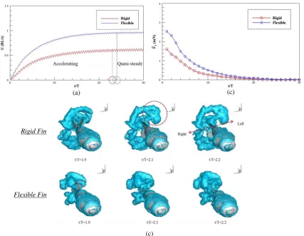
With the body-fin model shown in Figure 3(b) and the MBD algorithm developed in Ref. [27], we investigated the effect of fin flexibility on the performance of a self-propelled pufferfish. We found that the fish with flexible fins is able to swim approximately twice faster than that with rigid fins, which is attributed to a higher acceleration and a longer accelerating process, as shown in Figure 4 (a). Besides, the flexible fins could reduce the power consumption, thus resulted in an increase of efficiency. Figure 4 (b) illustrates the time-averaged total forceFT. The total forceFTof a pufferfish with flexible fins is larger than that with rigid fins, which indicates that the fish with flexible fins has a longer acceleration process. The total force decreases to zero after some motion periods, indicating that the fish reaches its cruising stage. Figure 4 (c) demonstrates the instantaneous wake structures for rigid and flexible fin cases. It is observed that the vortices generated by the rigid fins are more scattered in lateral directions, which contributes less to thrust generation and leads to higher power consumption. For the flexible fins, the vortices are shed from the fin tips and convert quickly to the downstream, thereby producing larger thrust force.
rigid undulatory body and an integrated system with both undulatory body and flexible fins. One advantage of our modeling tool based on multi-body dynamics algorism is that it can handle self-propel swimming with multiple degrees of freedom. This feature allows us to study the stability and maneuvering problems of complex bio-inspired underwater robots. Currently, the integration of the MBD tool with a controlling strategy (e.g., PID controller) is under development at our research group. The integrated code can be used to investigate the possible body and/or fin kinematics to achieve better stability or maneuver behaviors under various flow environments. The insights shed from our single-fin model may provide valuable guidance on the design of the fin kinematics used in our more complicated body-fin model.
(a) (c)
(c)
Rigid Fin
Flexible Fin
Figure 4 (a) Swimming speed evolutionary history for rigid and flexible fins. (b) Time histories of cycle-averaged total force. (c) Instantaneous vortex topology.
4 CONCLUSIONS
[image:9.595.72.500.226.557.2]advantages of providing detailed flow field data and exploring a larger parameter matrix, thus have become an indispensable approach for the study of biomimetic problems.
With different numerical tools, studies on ray-finned fishes can be categorized into two groups: single-fin model and body-fin model. The fins of ray-finned fishes possess distinctive features e.g., a thin and soft membrane strengthened by bony rays, anisotropic material property, individual actuation of each ray as well as actively controllable ray curvature and stiffness. Despite the complex design of ray-supported fish fins, there are still studies attempting to consider some of the key characters mentioned above [8], [9], [16], [22]. The important conclusions from their research are: 1) the ray flexibility may reduce the sensitivity of fin’s propulsion efficiency to the kinematics such as frequency and amplitude. 2) Appropriate cupping deformations can reduce the power expenditure of a caudal fin. 3) Actively controlled undulating motion can generate a vertical force which could be used for fish maneuvering while retaining a high thrust and efficiency. These insights may provide valuable guidance for the design of underwater vehicles.
To investigate the possible body-fin or fin-fin interactions, a body-fin model needs to be used. The body-fin model can swim either with a prescribed motion or with a self-propelled motion. The former case (prescribed motion) is usually used to study the complex hydrodynamics of a whole fish under steady swimming mode or maneuver behaviors, which could enrich our understanding of fish locomotion. The later case (self-propelled), however, allows researchers to investigate the stability and controllability problems of robotic fishes. The self-propelled body-fin model can also be used to explore the possible fish kinematics to keep stability under different flow environments and accomplish various maneuver behaviors if integrated with a proper control strategy.
ACKNOWLEDGEMENTS
The first author would like to thank the China Scholarship Council (CSC) and University of Strathclyde for the financial support during his study in the UK. Results were partially obtained using the ARCHIE-WeSt High Performance Computer (www.archie-west.ac.uk) based at the University of Strathclyde.
REFERENCES
[1] G. V Lauder and E. G. Drucker, “Morphology and Experimental Hydrodynamics of Fish Fin Control Surfaces,” IEEE J. Ocean. Eng., vol. 29, no. 3, pp. 556–571, 2004.
[2] F. E. Fish and G. V Lauder, “Passive and Active Flow Control By Swimming Fishes and Mammals,” Annu. Rev. Fluid Mech., vol. 38, no. 1, pp. 193–224, 2006.
[3] G. V. Lauder and P. G. A. Madden, “Learning from Fish: Kinematics and Experimental Hydrodynamics for Roboticists,” Int. J. Autom. Comput., vol. 4, pp. 325–335, 2006.
[4] G. V. Lauder, “Fish Locomotion: Recent Advances and New Directions,” Ann. Rev. Mar. Sci., vol. 7, no. 1, pp. 521–545, 2015.
[5] M. Saadat, F. E. Fish, A. G. Domel, V. Di Santo, G. V Lauder, and H. Haj-Hariri, “On the rules for aquatic locomotion,” Phys. Rev. Fluids, vol. 083102, pp. 1–12, 2017.
[6] F. E. Fish and G. V Lauder, “Control surfaces of aquatic vertebrates: active and passive design and function,” J. Exp. Biol., vol. 220, pp. 4351–4363, 2017.
[7] R. Mittal, “Computational modeling in biohydrodynamics: Trends, challenges, and recent advances,” IEEE J. Ocean. Eng., vol. 29, no. 3, pp. 595–604, 2004.
[9] K. Shoele and Q. Zhu, “Numerical simulation of a pectoral fin during labriform swimming,” J. Exp. Biol., vol. 213, pp. 2038–2047, 2010.
[10] K. Shoele and Q. Zhu, “Fluid-structure interactions of skeleton-reinforced fins: performance analysis of a paired fin in lift-based propulsion.,” J. Exp. Biol., vol. 212, pp. 2679–2690, 2009.
[11] Q. Zhu and XB Bi, “Effects of stiffness distribution and spanwise deformation on the dynamics of a ray-supported caudal fin,” Bioinspir. Biomim., vol. 12, no. 2, p. 26011, 2017.
[12] H. Dong, M. Bozkurttas, R. Mittal, P. Madden, and G. V. Lauder, “Computational modelling and analysis of the hydrodynamics of a highly deformable fish pectoral fin,” J. Fluid Mech., vol. 645, pp. 345–373, 2010.
[13] G. Liu, Y. Ren, H. Dong, O. Akanyeti, J. C. Liao, and G. V. Lauder, “Computational analysis of vortex dynamics and performance enhancement due to body-fin and fin-fin interactions in fish-like
locomotion,” J. Fluid Mech., vol. 829, pp. 65–88, 2017.
[14] T. Nakata and H. Liu, “A fluid-structure interaction model of insect flight with flexible wings,” J. Comput. Phys., vol. 231, no. 4, pp. 1822–1847, 2012.
[15] G. Li, U. K. Müller, J. L. Van Leeuwen, and H. Liu, “Body dynamics and hydrodynamics of swimming fish larvae: a computational study,” J. Exp. Biol., pp. 4015–4033, 2012.
[16] G. Shi, Q. Xiao, Q. Zhu, and W. Liao, 2019, “Fluid-structure interaction modeling on a three-dimensional ray-strengthened caudal fin,” Bioinspir. Biomim., (under review).
[17] M. Bozkurttas, H. Dong, R. Mittal, P. Madden, and G. Lauder, “Hydrodynamic Performance of Deformable Fish Fins and Flapping Foils,” 44th AIAA Aerosp. Sci. Meet. Exhib., no. January, pp. 1–11, 2006.
[18] X. Chang, L. Zhang, and X. He, “Numerical study of the thunniform mode of fish swimming with different Reynolds number and caudal fin shape,” Comput. Fluids, vol. 68, pp. 54–70, 2012.
[19] R. G. B. II, I. Borazjani, E. L. Blevins, and G. V Lauder, “Hydrodynamics of swimming in stingrays: numerical simulations and the role of the leading-edge vortex,” J. Fluid Mech., pp. 407–443, 2016. [20] J. BENEK, J. STEGER, and F. C. DOUGHERTY, “A flexible grid embedding technique with
application to the Euler equations,” in 6th Computational Fluid Dynamics Conference Danvers, American Institute of Aeronautics and Astronautics, 1983.
[21] K. Nakahashi, F. Togashi, and D. Sharov, “Intergrid-Boundary Definition Method for Overset Unstructured Grid Approach,” AIAA J., vol. 38, no. 11, pp. 2077–2084, Nov. 2000.
[22] R. Mittal, H. Dong, M. Bozkurttas, G. V. Lauder, and P. Madden, “Locomotion with flexible propulsors: II. Computational modeling of pectoral fin swimming in sunfish,” Bioinspiration and Biomimetics, vol. 1, no. 4, 2006.
[23] F.-B. Tian, H. Dai, H. Luo, J. F. Doyle, and B. Rousseau, “Fluid–structure interaction involving large deformations: 3D simulations and applications to biological systems,” J. Comput. Phys., vol. 258, pp. 451–469, 2014.
[24] C. Farhat and M. Lesoinne, “Two efficient staggered algorithms for the serial and parallel solution of three-dimensional nonlinear transient aeroelastic problems,” Comput. Methods Appl. Mech. Eng., vol. 182, no. 3–4, pp. 499–515, 2000.
[25] J. Degroote, R. Haelterman, S. Annerel, P. Bruggeman, and J. Vierendeels, “Performance of partitioned procedures in fluid-structure interaction,” Comput. Struct., vol. 88, no. 7–8, pp. 446–457, 2010. [26] P. Causin, J. F. Gerbeau, and F. Nobile, “Added-mass effect in the design of partitioned algorithms for
fluid-structure problems,” Comput. Methods Appl. Mech. Eng., vol. 194, no. 42–44, pp. 4506–4527, 2005.
[27] R. Li, Q. Xiao, Y. Liu, J. Hu, L. Li, G. Li, H. Liu, K. Hu, and L. Wen, “A multi-body dynamics based numerical modelling tool for solving aquatic biomimetic problems,” Bioinspiration and Biomimetics, vol. 13, no. 5, 2018.
[28] S. Alben, P. G. Madden, and G. V Lauder, “The mechanics of active fin-shape control in ray-finned fishes.,” J. R. Soc. Interface, vol. 4, no. 13, pp. 243–56, 2007.
[29] G. C. Lewin and H. Haj-Hariri, “Modelling thrust generation of a two-dimensional heaving airfoil in a viscous flow,” J. Fluid Mech., vol. 492, no. 492, pp. 339–362, 2003.
[31] P. D. Yeh and A. Alexeev, “Free swimming of an elastic plate plunging at low Reynolds number,” Phys. Fluids, vol. 26, no. 5, 2014.
[32] E. D. Tytell, “Median fin function in bluegill sunfish Lepomis macrochirus: streamwise vortex structure during steady swimming,” J. Exp. Biol., vol. 209, pp. 1516–1534, 2006.
![Figure 1 Various ray-fin models. (a) Caudal fin model of Shi et al. [16]. (b) Caudal fin model of Zhu and Shoele [8]](https://thumb-us.123doks.com/thumbv2/123dok_us/1353318.88932/5.595.89.509.248.674/figure-various-models-caudal-model-caudal-model-shoele.webp)
![Figure 3 Computational body-fin models reconstructed from experiments. (a) Crevalle Jack (Caranx hippos) fish [13]](https://thumb-us.123doks.com/thumbv2/123dok_us/1353318.88932/8.595.115.475.95.438/figure-computational-models-reconstructed-experiments-crevalle-caranx-hippos.webp)