International Journal of Innovative Technology and Exploring Engineering (IJITEE) ISSN: 2278-3075, Volume-8 Issue-10, August 2019
Abstract: The overhead for resource utilization in the round coding operation of security coding is large. Though lightweight protocols are used as a measure of provisioning, higher level of security in many real time applications, the need of key scheduling, key generation and s-box operation leads to large resource utilization. This resource consumption intern leads to large power consumption and area overhead. To minimize the resource utilization in this paper, a new resource optimization technique following resource reutilization scheme is proposed. The resource utilization is synchronized by the delay term instruction application in cryptography coding.
Index Terms: Security coding, resource optimization, resource reutilization, light weight coding
I. INTRODUCTION
Security in many applications has a critical requirement aspects with secure passwords, Applications such as secure payments, communications, storage, etc., demands for a high degree of security coding. Cryptography is a key element of secure communication. But existing cryptography approaches essential for secure applications, are not self-efficient. Cryptography is used as an approach to writing secret data in encrypted form. In various applications of usage ranging from diplomatic secret documents to critical war plans. Not surprisingly, the widespread development of computer communications has given evolution to new forms of cryptography.
Cryptography is essential when information and telecommunication is communicated over an unreliable media especially the Internet. From the evolution many approaches have been developed for security coding in cryptography application. [1] provides an overview of a security coding in wide area computing, and is a real application used by the Public Key Infrastructure (PKI). In [2] to interact with the intermediate level semantic translation architecture, the interval between intermediate linguistic languages and the low-level processes that humans use directly are used. Research activity in an insight on how to promote cooperation among service providers is presented in [3].
Revised Manuscript Received on August 05, 2019
Sunitha Tappari, Dept of Electronics and Telematics Engineering,
G.Narayanamma Institute of Technology and Science, JNTUH, Hyderabad, India.
K. Sridevi, Associate Professor, Dept. Of ECE GITAM Institute of
Technology, GITAM University, Vishakapatnam, India.
In [4] a secure unknown authentication system for distributed services, is suggested by group signature based identity, allowing users to prove access to data without revealing their identity. [5] presented a public auditing scheme using the Third Party Auditor (TPA), which performs data auditing for secure and efficient data exchange.[6] Introduces a compatible model of service based on dependencies recommended for business computing. The benefit of this specific model is ideal for advanced Dynamic Trust specifications for advanced Computing. It blocks the failure of single point and selects the appropriate service provider for service provisioning. [7] describes an authorization and approval protocol that indicates the main features of anonymous communication in the wide area network. The solution improves the current criteria to make the existing standards easier to synchronize. In order to ensure specialized security in cryptography environment, [8] suggested the work of a intermediate approach to introduce a trusted third party. A trust-overlay network [9] provides multiple data units for performing a reputation coding of trust between service providers and data source. An article describing the features of security coding is outlined in [10, 11]. An authentication protocol described in [12] indicates the main features of anonymous communications in distributed networks. Where in various service level and software level security measure were developed the hardware design are need to be improved. With the objective of developing a new security approach for cryptographic applications, hardware architectures using PRESNT [1] are developed in the recent past. The processing resource overhead is however large in count as observed.
To minimize resource overhead in this paper a new resource sharing approach with latency control is proposed. The existing PRESENT [1] architecture is modified with a register arbiter unit, resulting in improved performance. The rest of this paper is outlined in 6 sections, presenting the existing light weight approach in section 2. The proposed resource utilization is presented in section 3. Section 4 outlines the simulation results, concluding in section 5. The provision of security coding is, however, limited by resource constraints. To optimize the resource utilization in this paper, a new coding approach of resource utilization based on resource reusing is proposed.
Resource Optimized Security Coding In Light
Weight Security Protocol
I.LIGHT WEIGHT SECURITY CODING (PRESENT)
The provision of security coding is however, limited with resource constraint. To optimize the resource utilization in this paper, a new coding approach of resource utilization based on resource reusing is proposed. Security code, using light weight protocol called 'PRESENT' was outlined in [1]. The PRESNT algorithm has an input pattern of 64bit as input. The coding is performed based on the passed key bit, defined for a length of 80 or 128 bit length. Number of bits presented in a processing block are defined as the block length. Variable bit lengths are not considered and has a fixed bit length compatibility. The array vector is set of binary ‘1’ or ‘0’ of length lesser than the block or key length. For key bit representation the index term ‘I' defined by a length of 80 or 128 bits. In the processing of cryptography coding, the blocks are defined as segments of eight bit data, defined as segment of bytes. Bytes are stored in a table indicated for an input, output, or cipher key. One or both of the forms are represented by a value of n is given by,
All the bytes in the algorithm included in the combination of {b7,b6,b5,b4,b3,b2,b1,b0} as a combination of
their bit values (0, 1). These bytes are defined as field constituents used by the representative of the polygons:
(1)
In the calculation of the evaluation of computation overhead with the code fixed the overhead is given by GF (28) as,
(2) Although polynomial equations operate in the same way, the polynomial equations in this category are much different than a multiplier used compact field component. The properties of this category are self-contained. In addition, the difference in polynomial equations performed by a XOR and a shift operations given by,
(3)
The XOR refers to an XOR function between the bytes in each word from other words, which are derived from a full word. Thus, with the above equations,
(4)
Here the Shift is in two stages. In the first phase the polynomial equation is developed as c(x) = a (x) << b (x), and is equivalent to collecting powers,
(5)
Where,
The result, c(x) is not a four-byte word. So the second stage of the shift operation is to reduce the multiplication of the c(x) module. If the result is less than 4, it is reduced to a polynomial. This is made through x4+1 polynomial equation in PRESENT algorithm. The process of encoding is defined here as,
(6) A modular operation of a(x) and b(x), denoted by a(x) b(x), is a four-term polynomial defined by,
(7)
Where,
In PRESENT approach the round transformation does not have a festal structure. Instead, the round transformation contains uniform transformations, the three inverse transformations known as layers. Here every bite of the state is treated similarly. In an advanced trail strategy, each has its own function:
Linear Mixing Layer: Ensures high merging in multiple rounds.
Non-Linear Layer: parallel operation for S-box application in worst case non-linearity.
Key XOR layer: A simple XOR for intermediate state round key.
A key XOR layer is applied before the first round. The effect of this initial key XOR is to develop a cipher data with key in a round fashion which overcomes the plaintext attack. The round fashion key is iterative for 1st to last key, and an attacker can easily decrypt the information in such computing. The computing iteration and the logical resource used are observed to be higher in this coding. The latency observed in this case due to shift and XOR operation are limited in resource utilization in PRESNT approach.
II.RESOURCE OPTIMIZED CODING APPROACH (I-PRESENT)
The need for a new encryption standard became suspicious after the security arrangement appeared to be constraint of brutal attacks. Research began to develop and explore solution to develop new
International Journal of Innovative Technology and Exploring Engineering (IJITEE) ISSN: 2278-3075, Volume-8 Issue-10, August 2019
resulting in PRESENT approach. The algorithm uses a block length and the key length of j bits. The specified code length for the coding is of length 80, 128 bit. PRESENT, a FIPS-certified cryptographic algorithm. It is a block cipher which can operate through a variable-length block using variable key length. Standard uses a 80-bit and 128-bit key to encrypt 80 or 128 bit long data blocks. The algorithm is written in such a way that the block length or the key length is easily expanded into multiples of 32 bits and is specially designed to make the processor more efficient using hardware or software.
[image:3.595.326.527.138.202.2]The PRESENT operational block diagram is shown in Fig 1.
Fig 1: Block Diagram Of Lightweight PRESENT Security Coding [1]
The modified structure of the proposed approach is
presented in Fig 2 below
Fig 2: Block Diagram Of Resource Controlled Light Weight PRESNT Security Coding.
The past approach has a resource overhead constraint which is due to large recursive operation in key generation and key scheduling approach. Though the approach is efficient, the resource overhead is large to overcome the resource constraint, a resource delay tuned resource optimization scheme is proposed. Here the functionality is based on the operating clock and the delay generated. The operating clocks are applied for processing unit at the same time to process data for data exchange in synchronization. In the scheduling approach, the existing approach has a clock period observed as a proportion of the maximum period of delays.
[image:3.595.62.274.210.336.2]However, if a key is on schedule, the operating delays are in proportion to maximum delay, leading to the higher clock speed. In this scheme, processing resource banks are issued with clock pulsing as a single calculation unit of delay parameter. The proposed resource scheduling with allocated delay is given in Fig 3.
Fig 3: Delay Clock And Register Allocation For Operation
In the computing of logical and shift operation, each activity will be delayed by the instruction decoding and execution. The clock delays of is provided based on the command and header type of each instruction. For an instruction execution, for each operation a register is to be allocated, where for each allocation a clock delay is needed as synchronization value, here clock is calculated at each node, resulting an overhead .,
(8)
Here, is a function of instruction execution overhead and is the clock allocation for instruction execution. The parameters are computed as,
(9)
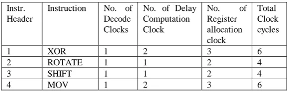
Here a set of 4 operational instructions is used as listed in Table 1.
Table 1: Instruction with respective delay
Instr. Header
Instruction No. of Decode Clocks
No. of Delay Computation Clock
No. of Register allocation clock
Total Clock cycles
1 XOR 1 2 3 6
2 ROTATE 1 1 2 4
3 SHIFT 1 1 2 4
4 MOV 1 2 3 6
The decode cycle is defined as a time taken for instruction to fetch and decode for operation. Computation delay is time for the delay in computation for each instruction that has to be assigned for register allocation. The register allocation delay is the time taken for each register allocation. This overhead is minimized by resource deployment in common instruction type. In this approach the common clocking instructions are realignment as a set of instruction and a common delay in register allocation is defined. This realignment is made as one time POST coding, and the delay is buffered as a reference array. When the instructions executed in this case doesn’t have to go for clock delay computation and a reference to the delay buffer can result in delay monitoring. The updated instruction set
[image:3.595.63.274.433.614.2] [image:3.595.298.587.476.569.2]Table 2: Aligned clock reference table
Instr. Header Instruction Delay
Register
4 MOV 6
1 XOR 6
3 ROTATE 4
2 SHIFT 4
This approach diminished the clock latency from 15 to 12, thus eliminating the computing overhead. For example, using the resource deployment a delay of 6 cycles is reduced. The proposed clock allocation process has an allocation of delay values for each instruction pre computed. In the cryptography coding these operations are scheduled to give optimal resource utilization. The operating result of the developed approach is illustrated in following section.
III.EXPERIMENTAL RESULTS
A HDL development for the proposed work is simulated for timing observation on Aldec tool. For the implementation of the proposed approach, the developed design is targeted to two FPGA devices. The evaluating metrics of power, delay, throughput and the area is computed. The obtained results are as illustrated below,
Fig 4: Instruction Set Illustration
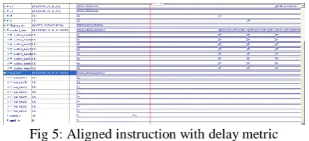
[image:4.595.54.284.71.144.2]The original instruction sets, the input signal and the contents of the interconnect signal are shown in Fig 4. At the reset level, the signals were cleared for the values not signed, and the past latch data were cleared for a new simulation. A set of instruction is buffered. For the test validation 4 instruction operation is performed to perform key generation and encryption. The output result is illustrated as updated data, wherein signal 'final_data' is illustrated as a final output result illustrated in Fig 5.
Fig 5: Aligned instruction with delay metric
The resulted timing observation is shown in resource alignment for a set of instruction as illustrated in Fig 6. The proposed approach defines the clock delay from the reference table, the clock cycle for operational clock and
[image:4.595.319.536.262.392.2]synchronization operation is passed to 'r1' and 'r2' signal respectively.
Fig 6: Delay table.
The clock delay is reduced from 54 to 49 system clock for outlined technique compared to exiting PRESNT approach. Obtained result is shown in Fig 7 below.
Fig 7. Clock Count Observation
To observe the security coding over the proposed resource optimized logic, the below example is evaluated as,
Example:
A 128-bit block of data is considered for the, Designed system given as
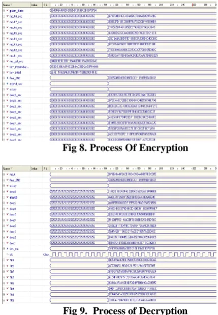
Encryption:
Plain Text: 3243f6a8885a308d313198a2e0370734
Key:
2b7e151628aed2a6abf7158809cf4f3c
Cipher Text (Encrypted output):
3925841d02dc09fbdc118597196a0b32
The encrypted output is an input to the decryption. After the Whole Process, the Obtained Decrypted data are given as
Decryption:
Dec output (Plain Text):
3243f6a8885a308d313198a2e0370734
[image:4.595.58.278.363.489.2] [image:4.595.58.280.621.722.2]International Journal of Innovative Technology and Exploring Engineering (IJITEE) ISSN: 2278-3075, Volume-8 Issue-10, August 2019
Fig 8. Process Of Encryption
Fig 9. Process of Decryption
The FPGA implementation is obtained targeting to Xilinx FPGA device. For the targeted FPGA device, obtained synthesis report is illustrated in Fig 10.
Fig 10. Implementation synthesis for targeted FPGA.
Towards power analysis Xilinx Power analyzer ‘x-power analyzer’ is used. This developed design on implementation is analyzed for the power rating using this tool. A power of 181mW of power specification for the developed approach is illustrated.
Fig 11: Power Observation
Timing observation of the implementation is observed as;
Minimum period: 7.69ns (Max.Freq:129.984MHz)
Minimum input arrival time before clock: 2.950ns.
Maximum output required time after clock: 3.615ns.
[image:5.595.318.536.201.663.2]The FPGA implementation of the developed system, targeting to the FPGA device is presented in Fig 12. This approach is designed using interconnection of logical block units and I/O interface.
[image:5.595.49.263.410.553.2]Fig 12: Routing into targeted FPGA
Fig 13: Placement of logical unit
Fig 14: Chip Layout Outline For Targeted Device
FPGA device is targeted and the implementation metrics are validated, area, latency and throughput is measured as outlined below.
The power consumed by a logical device is given by,
(10)
[image:6.595.316.525.58.189.2]Where is the capacitance, is the voltage swing, and is the operating frequency of operation for k used resource block. Analysis of the power consumption is presented in table 3 below.
Table 3: Power Consumption Analysis FPGA
FAMILY
POWER ( )
PRESENT[1] I-PRESENT
SPARTAN 281.5 181
VERTEX 874.5 622.8
Fig 15. Power Analysis For Developed Approach
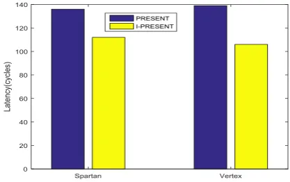
The latency of the design system tested for a different FPGA device is presented in table 4 below. The path delay observed by the developed approach is minimized by resource utilization as compared to PRESENT coding approach.
Table 4: Delay latency
FPGA
FAMILY
LATENCY (CYCLES)
PRESENT[1] I-PRESENT
SPARTAN 136 112
VERTEX 139 106
[image:6.595.58.279.189.464.2]
Fig 16. Latency Comparison Of Developed Approach
To evaluate implementation overhead and performance metric, area and throughput for the developed approach is presented. The system throughput is defined by,
(11)
[image:6.595.315.556.349.658.2]Where, Fmax, Bsize and LAT are defined as maximum operating frequency, operating block size and LAT is the latency of the system.
[image:6.595.60.279.557.684.2]Table 5: System Throughput
Fig 17. Throughput Comparison FPGA
FAMILY
THROUGHPUT (MBPS)
PRESENT [1]
I-PRESENT
SPARTAN 186.42 193.34
International Journal of Innovative Technology and Exploring Engineering (IJITEE) ISSN: 2278-3075, Volume-8 Issue-10, August 2019
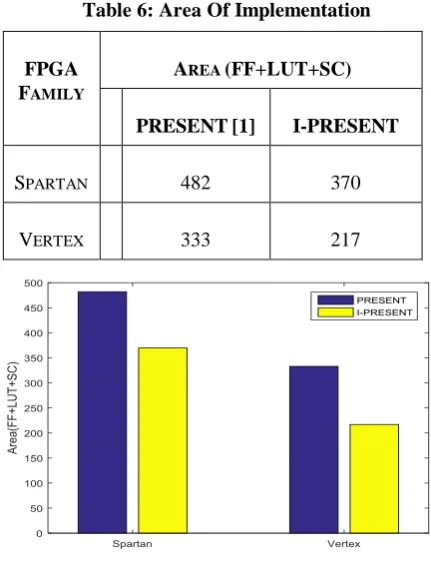
Table 6: Area Of Implementation
Fig 18. Area of implementation
Where, LUT, FF and SC are the lookup table, flip flop and slices used in the FPGA device respectively.
IV. CONCLUSIONS
In this paper, a new resource optimization is proposed which realizes an enhancement to the speed of operation by applying finite field arithmetic approach to reduce the computation time for Encrypting message using PRESENT. From the observations made in the implemented PRESENT module, it is observed, the chip could support 128-bit message for Encryption with a Real time speed of 71.8MHz.The Throughput found is about 9184 Mbps. For the implemented system the resource occupied on Virtex2p targeted chip about 9419 slices. From these observations the implementation of a resource optimized Encryption unit is achieved. This could be used for High speed remote device security provisioning applications.
REFERENCES
1. Tay, J.J.; Wong, M.L.D.; Wong, M.M.; Zhang, C.; Hijazin, I. “Compact FPGA implementation of PRESENT with Boolean S-Box”. In: Proceedings of the 6th Asia Symposium on Quality Electronic Design (ASQED), Kula Lumpur, Malaysia, 4–9 August 2015; pp. 144–148. 2. Batra, I.; Luhach, A.K.; Pathak, N.; “Research and Analysis of
Lightweight Cryptographic Solutions for Internet of Things”. In: Proceedings of the Second International Conference on Information and Communication Technology for Competitive Strategies, Udaipur, India, 4–5 March 2016; p. 23.
3. Patil, A.; Bansod, G.; Pisharoty, N.; “Hybrid Lightweight and Robust Encryption Design for Security in IoT”.Int. J. Secur. Its Appl. 2015, 9, 85–98.
4. Shamir, A.; Biryukov, A.; Perrin, L.P. “Summary of an Open Discussion on IoT and Lightweight Cryptography”. In: Proceedings of Early Symmetric Crypto Workshop; University of Luxembourg: Luxembourg, 2017.
5. Biryukov, A.; Perrin, L. “State of the Art in Lightweight Symmetric Cryptography”, International Association for Cryptologic Research: Esch-sur-Alzette, Luxembourg, 2017.
6. Wang, Y.; Ha, Y. “FPGA-based 40.9-Gbits/s masked AES with area optimization for storage area network”.IEEE Trans. Circuits Syst. II Express Briefs 2013, 60, 36–40.
7. McLoone, M.; McCanny, J.V. “PRESENT FPGA implementations utilising look-up tables”. J. VLSI Signal Process. Syst. Signal Image Video Technol. 2003, 34, 261–275.
8. Liu, F.; Ji, W.; Hu, L.; Ding, J.; Lv, S.; Pyshkin, A.; Weinmann, R.-P. “Analysis of the SMS4 block cipher”. ACISP 2007, 4586, 158–170. 9. Lee, S.W.; Moon, S.-J.; Kim, J.N. “High-Speed Hardware Architectures
for ARIA with Composite Field Arithmetic and Area-Throughput Trade-Offs”. ETRI J. 2008, 30, 707–717.
10.Bansod, G.; Raval, N.; Pisharoty, N. “Implementation of a new lightweight encryption design for embedded security”. IEEE Trans. Inf. Forensics Secur. 2015, 10, 142–151.
11. Kitsos, P.; Sklavos, N.; Parousi, M.; Skodras, A.N. “A comparative study of hardware architectures for lightweight block ciphers”. Comput. Electr. Eng. 2012, 38, 148–160.
12.Satoh, A.; Morioka, S.; Takano, K.; Munetoh, S. “A compact PRESENT hardware architecture with S-box optimization”. Asiacrypt 2001, 2248, 239–254.
13.Rudra, A.; Dubey, P.K.; Jutla, C.S.; Kumar, V.; Rao, J.R.; Rohatgi, P. “Efficient PRESENT encryption implementation with composite field arithmetic”. CHES 2001, 2162, 171–184.
14.Canright, D. “A very compact S-box for AES”. In International Workshop on Cryptographic Hardware and Embedded Systems; Springer: Berlin/Heidelberg, Germany, 2005; pp. 441–455.
15.Guo, X.; Chen, Z.; Schaumont, P. “Energy and performance evaluation of an FPGA-based SoC platform with AES and PRESENT coprocessors”. Lect. Notes Comput. Sci. 2008, 5114, 106–115.
16.Bogdanov, A.; Knudsen, L.R.; Leander, G.; Paar, C.; Poschmann, A.; Robshaw, M.J.B.; Seurin, Y.; Vikkelsoe, C. “PRESENT: An ultra-lightweight block cipher”. CHES 2007, 4727, 450–466.
FPGA
FAMILY
AREA (FF+LUT+SC)
PRESENT[1] I-PRESENT
SPARTAN 482 370