International Journal of Innovative Technology and Exploring Engineering (IJITEE) ISSN: 2278-3075, Volume-8 Issue-9, July 2019
Abstract: This paper presents a quarter-wave patch antenna for GPS application which is realized by using shorting pins. The impact of the shorting relies upon the distance between the shorting posts, the radius of each shorting post, the number of shorting posts used and the height of the shorting posts which is determined by the thickness of the substrate used (which is 1.6mm for FR-4 substrate). A Right Hand Circularly Polarized Microstrip patch antenna with feed line for GPS frequency (1.575 GHz) is designed, simulated and fabricated. Simulation is done using ADS (Advanced Design System) and a fabricated prototype of the both the shorted and unshorted proposed antenna have been measured using Agilent Vector Network Analyzer.
Index Terms: GPS, Microstrip patch antenna, Quarter-wave, Rectangular Patch.
I. INTRODUCTION
Compact MSAs have been realized by using either shorting posts (pins) or shorting wires between the patch and ground [2]-[8]. The shorted microstrip patch antenna is a compact antenna but it suffers from the disadvantage that more number of shorting pins is required thereby making fabrication process harder especially when manufactured in larger quantities [11]. Shorting pins are inserted between the patch and the ground plane generally perturbs the surface current distribution on the patch [14].
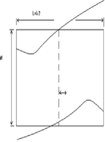
A rectangular micro strip antenna operating in the fundamental TM10 mode has a resonant length which is equal to λ/2 [1]; the voltage distribution along its length is shown in figure 1. The zero potential field is along the line OO to the ground plane, and by using only 50% of the patch a shorted RMSA with reduced size is obtained with resonant length equal to λ/4. The rectangular patch antenna so far is a half-wave rectangular patch. The electric field distribution under the patch is given by Eocos (πx/L). At the radiating edge which is on the right the electric field is minimum, zero in the middle (i.e. at x = λ/2), becomes maximum at the left radiating edge with a phase reversal of 180º (i.e. the field distribution keeps on changing in amplitude and sign).
Revised Manuscript Received on July 09, 2019.
S. SINDHUJA, Research Scholar, Department of Electronics & Communication Engineering, Bharath Institute of Higher Education and Research, Chennai, Tamil Nadu, India.
[image:1.595.322.506.175.423.2]E. KANNIGA, Professor, Department of Electronics & Communication Engineering, Bharath Institute of Higher Education and Research, Chennai, Tamil Nadu, India.
Fig. 1. Field distribution of the fundamental TM10 mode of RMSA
Since the electric field is zero at the plane x=L/2, an electric wall is formed there by means of the shorting posts. This phenomenon however does not change the field distribution under the patch. One-half of the patch antenna can now be discarded. [10, 12-15]
The resonating frequency of quarter-wave and that of the half-wave rectangular patch antenna are more or less the same. Rectangular patch geometry of this type is called a quarter- wave patch because the separation between the radiating edge and the electric wall is about λg/4. The characteristics of the quarter wave patch geometry are derived from the half-wave patch and are more or less the same. A quarter-wave patch can be used in applications where small-sized antennas are needed and deterioration in cross polarization characteristics can be tolerated. The major differences are that the quarter wave patch has one radiating edge compared to two for the half-wave patch. This physical difference is responsible for all the differences in antenna characteristics:
1. The E-plane pattern of the quarter-wave patch becomes broader because the array effect of two radiating edges for a half-wave patch is absent
here. Also the half-length nature of the patch gives rise
Design and Development of 1.575 Ghz
Quarter-Wave Patch Antenna with Feed Line
to a cross-polarized Eθ component in the H plane.
2. The radiation conductance Gr of a quarter-wave patch is due to radiation from a single edge. Its value is lowered by a factor of 2 compared to that obtained for half-wave patch. Therefore the radiation resistance at resonance will be two times. Numerical calculations show that ξr is not equal to 1. 3. The stored energy in quarter–wave patch is exactly one half of that of the half-wave patch because of identical field distribution over half the area.
4. The bandwidth is same for both the quarter-wave patch and the half-wave patch.
II. CALCULATIONOFTHEPATCHANTENNA DIMENSIONS
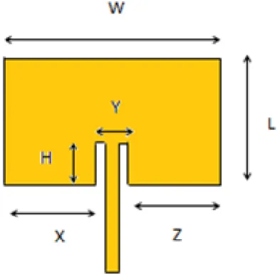
[image:2.595.84.279.546.742.2]The geometry of a single antenna element is shown in the Fig. 2.
The width and length of the radiating surface is given by,
(1)
Where,
Velocity of light, c = 3 x 10⁸ m/s Frequency, f = 1.575 GHz Relative Permittivity, ξr = 4.6
So substituting the values in equation (1) we get W = L = 44. 4mm. The depth of the feed line into the patch is given by the formula
(2)
Substituting the value of L in equation (2) we get H = 18.25 mm. The value of H is directly proportional to the reflected power S11.
Fig. 2. Top view of the Microstrip patch antenna with feed line
The other dimensions are,
(3)
(4)
he value Y is inversely proportional to the coupling between the antenna and the Microstrip.
A.Design of the Quarter-wave patch antenna with shorting posts
Compared to other miniaturization techniques, the proposed shorting technique is much simple and is mechanically robust.
Fig. 3. Top view of proposed shorted antenna
International Journal of Innovative Technology and Exploring Engineering (IJITEE) ISSN: 2278-3075, Volume-8 Issue-9, July 2019
[image:3.595.312.545.50.322.2]B.Design steps involved in the miniaturization of microstrip patch antennas
Fig. 4. Design steps
C.Simulation using ADS
In this study, Advanced Design system software was used for computing the radiating characteristics of the shorted microstrip patch antenna. In order to match the impedance of the feed line to the patch an inset cut is introduced which eliminates the need for any additional matching element. It is necessary to properly control the inset position to match the impedance.
Table I. Design Parameters of the Antenna
Design Parameter Value
Substrate material FR4
Relative Permittivity of the substrate
4.6
Thickness of the dielectric substrate
1.6 mm
[image:3.595.63.301.97.306.2]Design Frequency 1.575 GHz
Fig. 5. Design of unshorted microstrip patch antenna
[image:3.595.311.547.353.578.2] [image:3.595.57.276.471.674.2][image:4.595.84.262.56.249.2]
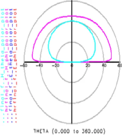
Fig. 7. Radiation pattern for unshorted microstrip patch antenna
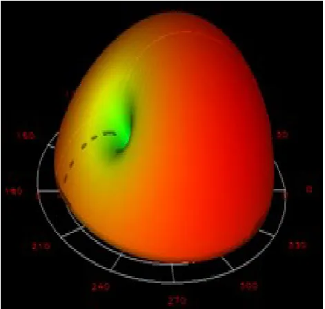
Fig. 8. Radiation pattern for unshorted microstrip patch antenna (3D)
[image:4.595.64.288.292.506.2]Fig. 9. Design of shorted microstrip patch antenna
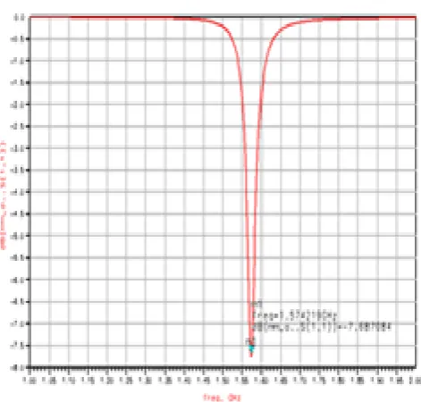
Fig. 10. Simulation result for shorted microstrip patch antenna
The simulation results show Return loss at center frequency, 3D polar plot of gain and directivity in E and H plane.
[image:4.595.329.530.338.561.2] [image:4.595.59.295.545.746.2]International Journal of Innovative Technology and Exploring Engineering (IJITEE) ISSN: 2278-3075, Volume-8 Issue-9, July 2019
[image:5.595.65.290.307.573.2]Fig. 12. Radiation pattern for shorted microstrip patch antenna (3D)
Fig. 13.Comparison of Simulation results for unshorted and shorted microstrip patch antenna
Table II. Simulation Results Parameter
of Study
Value obtained
Conventional Proposed design
S11, Return loss
-7.68 dB -9.68 dB
Ae, Effective Antenna Area
19.71 cm2 9.9 cm2
D.Experimental Results
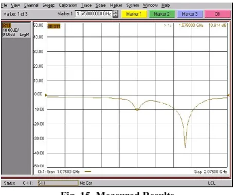
Both the half wave and quarter wave inset-fed microstrip patch antenna have been fabricated and tested using Agilent Vector Network Analyzer. There is a good match between the simulated and experimental results.
[image:5.595.315.567.431.662.2]Fig. 14. Comparison of the size of the fabricated prototypes of a conventional microstrip patch antenna
and shorted patch antennas
Fig. 15. Measured Results
III. CONCLUSION
In this paper, shorting posts have been used to reduce the input impedance on the periphery of the half of the patch antenna. The fabrication is carried out for both the shorted and unshorted patch antennas with both operating at the same frequency band in their fundamental TM10 mode. The proposed work provides an insight into the functioning of widely used Microstrip patch antenna element with shorting posts. As future work, techniques like introducing slots, truncating of the patch edges and changing of substrate may be done for further improvement of the design.
IV. ACKNOWLEDGMENT
We would like to thank Dr. R. VENKATESAN Scientist-G & Programme Director Ocean Observation Systems, National Institute of Ocean Technology, Chennai and Dr. P. SIVASANKAR Assistant Professor, Department of Electronics Engineering, National Institute of Technical Teachers, Training and Research, Chennai and Dr. Dr. M. SUNDARARAJAN, Professor and Dean Department of ECE/R&D, Bharath Institute of Higher Education and Research, Chennai as continuous supporters to bring effective output in my research work. And I also submit my thanks to the members of Research and Development and
CEDSE Bharath Institute of Higher Education and Research, Chennai.
REFERENCES
1. S.Sindhuja, S.V. Saravanan “Miniaturisation Using Shorting Posts in C-Shaped and H-Shaped Microstrip Patch Antennas for GPS Applications” International Journal of Recent Technology and Engineering (IJRTE), Volume-7 Issue-5S2, January 2019.
2. Rathod, Shivraj & Awale, Raval & Ray, Dr. (2018). Shorted Circular Microstrip Antennas for 50Ω Microstrip Line Feed with Very Low Cross Polarization. Progress In Electromagnetics Research Letters, Vol. 74. 91-98.
3. Podilchak, S. K., A. P. Murdoch, and Y. M. M. Antar, “Compact, microstrip-based folded-shorted patches: PCB antennas for use on microsatellites," IEEE Antennas Propag. Mag., Vol. 59, No. 2, 88-95, April 2017.
4. Rezazadeh, N. and L. Shafai, “A compact microstrip patch antenna for civilian GPS interference mitigation," IEEE Antennas Wireless Propag. Lett., Vol. 17, No. 3, 381-384, March 2018.
5. S.Sindhuja, S.V. Saravanan “Design and simulation of miniaturized microstrip patch antennas using shorting techniques for GPS Applications”, Journal of Advanced Research in Dynamical and Control Systems, Vol-9, Issue-9, pp. - 220-227, 2017.
6. Chapari, A., A. Zeidaabadi Nezhad, and Z. H. Firouzeh, “Analytical approach for compact shorting pin circular patch antenna,” IET Microwaves Antennas Propag., Vol. 11, No. 11, 1603-1608, 2017. 7. Rathod, S. M., R. N. Awale, and K. P. Ray, “Analysis of a single shorted
rectangular microstrip antenna for 50- microstrip line feed," 2016 International Symposium on Antennas and Propagation (APSYM), 1-4, Cochin, 2016.
8. Zhang, X. and L. Zhu, “Patch antennas with loading of a pair of shorting pins toward flexible impedance matching and low cross polarization," IEEE Trans. Antennas Propag., Vol. 64, No. 4, 1226-1233, April 2016. 9. Zhang, X. and L. Zhu, “An impedance-agile microstrip patch antenna with
loading of a shorting pin," 2015 Asia Pacific Microwave Conference (APMC), 1-3, 2015.
10.Balanis, C.A.: ‘Advance engineering electromagnetics’ (John Wiley & Sons, 2012, 2nd edn)
11.Deshmukh, A. A. and K. P. Ray, “Broadband shorted sectoral microstrip antenna” Progress in Electromagnetics Research C, Vol. 20, 55-65, 2011. 12.C.A. Balanis, Modern Antenna Handbook, John Wiley & Sons, 2008. 13.Ahmed H. Raja “Study of Micro Strip Feed Line Patch Antenna”,
Antennas and Propagation International Symposium, vol. 27, pp. 340-342 December 2008.
14.Kumar, G. and K. P. Ray, Broadband Microstrip Antennas, Artech House, Norwood, MA, USA,2003.
15.Wong, K. L., Compact and Broadband Microstrip Antennas, John Wiley & Sons, Inc., New York, 2002.
AUTHORSPROFILE
[image:6.595.62.291.263.453.2]International Journal of Innovative Technology and Exploring Engineering (IJITEE) ISSN: 2278-3075, Volume-8 Issue-9, July 2019