Abstract: This project aims for the construction and
implementation of the Coaxial probe feed microstrip array antenna for radar applications. As the Continuous Wave Frequency Modulated (CWFM) radar can together transfer and to accept the signals, whatever that can be used for a bistatic radar for consideration of weather and temperature. The single patch, 1x4, 2x2, 4X4 coaxial probe feed is to design at a frequency of 1.48GHz by using RT duriod (r = 2.2) dielectric substrate for a
bandwidth of 15MHz. For Microstrip antenna array elements is to connect with inter-component configuration of 0.8λ. in both horizontal and vertical directions. The microstrip patch array antenna was constructed and implemented by using HFSS (High Frequency Structure Simulator) and comparison of various descriptions of array antennas by using feeder network in circuit construction and to check the isolation between the two antennas for bistatic radar.
Index Terms: Microstrip patch array antenna, Bistatic radar, isolation, HFSS.
I. INTRODUCTION
Microstrip antenna performance an important factor in wireless communication systems. Microstrip patch antenna consisting of a transmitting patch on one side of the dielectric substrate that has the ground plane any other wayside. These types of antenna consist of three sheets. The top sheet is radiating patch and the intermediate sheet is a dielectric substance, the bottom sheet is ground plane[2][4]. The material is used for the top and bottom sheets are used for copper material and RT Duriod is used as a dielectric substance. Based on emission uniqueness of the array antenna is designed. For single antenna emission pattern is extensive and directivity is less[3][4]. To increase directivity narrow beam width array antenna is used.
The coaxial probe feed is one of the most common feeding techniques for microstrip antenna. In this technique, the feed can be located any desired area inside the patch to match the input impedance of the patch antenna. The inner conductor of the coaxial connector is extended through the dielectric is attached to the radiating patch of the antenna that the outer
Revised Manuscript Received on September 2, 2019.
B. SIVA SAI REDDY, Electronics and Communication Engineering,
SVEC College of Engineering, Tirupati, India.
P. PARVATHI, National Atmospheric Research Laboratory, Gadanki,
Tirupati, India.
B. SENTHIL KUMAR, Electronics and Communication Engineering,
SVEC College of Engineering, Tirupati, India.
.
conductor is connected to the ground plane. In these microstrip patch antenna can be used to design by using HFSS and also to check isolation between the two antennas for bistatic radar.
II. MICROSTRIPPATCHARRAYANTENNA In this paper, coaxial probe feed patch antenna array has been designed by using feeder network in circuit design at a center frequency of 1.48GHz using a dielectric substance as RT Duriod with ∊r= 2.2 and thickness (h) = 0.3175cm. The dielectric constant is commonly in the length of 2.2 ≤ ∊r ≤ 12[4]. The arrays elements are connected with the inner component configuration of 0.8λ in both horizontal and vertical directions. For the design of probed feed microstrip array antenna is used for the transmission line design.
The specifications of the antenna are return loss, bandwidth, VSWR, radiation pattern, gain, directivity and to check isolation between the two antennas are determined by using the High Frequency Structure Simulator. It is used for antenna, antenna arrays, filters and high frequency ranges. An Iterative solver is used for simulation.
A. Design Equations
The expected antenna design can be determined by using the formulas[2] given below.
The width of the patch can be calculated as W= c/2fr x √2/∊r+1 (1)
Where c is the speed of the light, fr is the running frequency of the antenna, ∊r is the constant of the dielectric substrate. The diameter of the patch can be calculated by using the following equations:
∊reff = ∊r+1/2 +∊r -1/2(1+12 h/w)-1/2 (2)
Where
∊
reffis
effective dielectric constant, h is the thickness of the dielectric substrate.Leff =
c/2f
r √∊reff (3) Where Leff is that the effective length of the patch.∆L= 0.412xh (∊reff +0.3) (w/h+0.264)/ (∊reff – 0.258) (w/h +0.8) (4) Where ∆L is the extended patch length.
L = Leff – 2x∆L (5) Where L is the actual patch length.
The location of the feed location can be calculated along x-axis and y-axis were given as
Xf = L/2 √∊reff (6)
Construction and Implementation of Coaxial
Probe Feed Microstrip Patch Array Antenna
Where Xf has the desired frequency along X-axis. Yf = W/2 (7) Where Yf has the desired frequency along Y-axis.
B. Feeder Network in Circuit Design
[image:2.595.311.547.45.291.2]The λ/4transformer is the perfect procedure for impedance is identical[1]. While construction of feeder network plays important for impedance from source to load.
Figure 1: λ/4 of a feeder network in circuit design
III.STRUCTUREOFCOAXIALPROBEFEED MICROSTRIPPATCHANTENNA CONSTRUCTION
INHFSS
By using HFSS single probe feed, 1x4, 2x2 and 4x4 coaxial probe feed microstrip patch array antenna is constructed. The dimensions and constructions of all these antennas are shown below.
A. Coaxial Probe Feed Patch Antenna Design 1.Single Coaxial Probe Feed Microstrip antenna
In these types of a microstrip patch antenna, the feed can be located inside the patch to match the transmission line of input impedance 50Ω by using an input impedance of the λ/4 transformer.
TABLE 1: Specifications of Single Coaxial Probe feed Patch Antenna
Parameters Values of Rectangular
patch (cm)
Description
Hs 0.3175 The Thickness
of substrate
εr 2.2 Dielectric
Constant
W 8.962 Width of the
patch
L 6.43 Length of the
patch
D 0.44 Diameter of the
inner conductor of probe
d0 0.127 Diameter of the
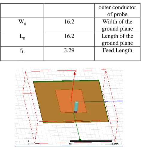
outer conductor of probe
Wg 16.2 Width of the
ground plane
Lg 16.2 Length of the
ground plane
fL 3.29 Feed Length
Figure 2: Coaxial Probe Feed for rectangular patch antenna
TABLE 2: Specifications of Coaxial Probe feed Rectangular Array Antenna
Factors Values for Array
Antenna (cm)
Information
Hs 0.3175 The Thickness
of the Substrate
εr 2.2 Dielectric
Constant
W 8.962 Width of the
Patch
L 6.43 Length of the
Patch
D 0.44 Diameter of the
inner conductor of probe
d0 0.127 Diameter of the
outer conductor of probe
Wg 16.2 Width of the
ground plane
Lg 16.2 Length of the
ground plane
fL 3.29 Feed Length
W50 0.960998 Width of 50 Ω
λ/4transformer
L50 3.69324 Length of 50 Ω
λ/4transformer
W70.7 0.549841 Width of 70.7 Ω
λ/4transformer
L70.7 3.75462 Length of 70.7
Ω λ/4 transformer
W100 0.277378 Width of 100 Ω
λ/4transformer
L100 3.81825 Length of 100 Ω
λ/4transformer
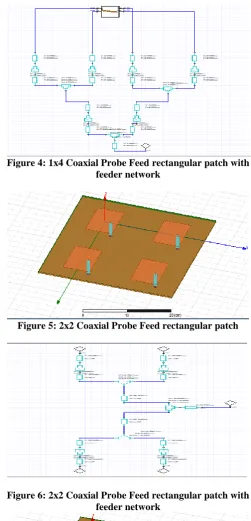
Figure 3: 1x4 Coaxial Probe Feed rectangular patch
Figure 4: 1x4 Coaxial Probe Feed rectangular patch with feeder network
[image:3.595.45.287.70.690.2]Figure 5: 2x2 Coaxial Probe Feed rectangular patch
[image:3.595.47.284.82.695.2]Figure 6: 2x2 Coaxial Probe Feed rectangular patch with feeder network
[image:3.595.303.552.540.681.2]Figure 8: 4x4 Coaxial Probe Feed rectangular patch with
feeder network.
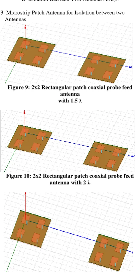
B. Isolation Between Two Antenna Arrays
[image:4.595.312.542.48.186.2]3. Microstrip Patch Antenna for Isolation between two Antennas
Figure 9: 2x2 Rectangular patch coaxial probe feed antenna
with 1.5 λ
Figure 10: 2x2 Rectangular patch coaxial probe feed antenna with 2 λ
Figure 11: 2x2 Rectangular patch coaxial probe feed antenna with 2.5 λ
Figure 12: 2x2 probe feed circuit for antenna design for isolation between two antennas is same for 1.5,2 and 2.5 λ
[image:4.595.301.546.237.360.2]Values
[image:4.595.46.284.272.759.2]Figure 13: 4x4 Rectangular patch coaxial probe feed antenna with 1.5 λ
Figure 14: 4x4 Rectangular patch coaxial probe feed antenna with 2 λ
[image:4.595.303.535.531.670.2]Figure 16: 4x4 probe feed circuit for antenna design for isolation between two antennas is the same for 1.5,
2 and 2.5 λ values IV.SIMULATIONRESULTS
Using High Frequency Structure Simulator (HFSS) the coaxial probe feed microstrip array antennas are constructed and implementation results are displayed below.
A. Coaxial Probe Feed Patch Antenna Construction Results
1.Single Coaxial Probe Feed Microstrip antenna:
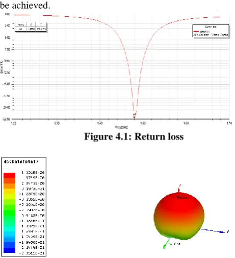
[image:5.595.323.533.43.318.2]For single coaxial probe feed microstrip antenna for Return loss (S11) of -22.4713dB and bandwidth of 20MHz can be achieved.
Figure 4.1: Return loss
Figure 4.2: 3D Radiation pattern
[image:5.595.48.265.50.189.2]2.1x4 Coaxial Probe Feed Microstrip Array Antenna For 1x4 coaxial probe feed microstrip antenna for Return loss (S11) of -19.9063dB and bandwidth of 20MHz can be achieved
Figure 4.3: Return loss
Figure 4.4: 3D Radiation pattern
[image:5.595.47.278.364.617.2]3.2x2 Coaxial Probe Feed Microstrip Array Antenna For 2x2 coaxial probe feed microstrip antenna for Return loss (S11) of -72.555dB and bandwidth of 20MHz can be achieved
Figure 4.5: Return loss
Figure 4.6: 3D Radiation pattern
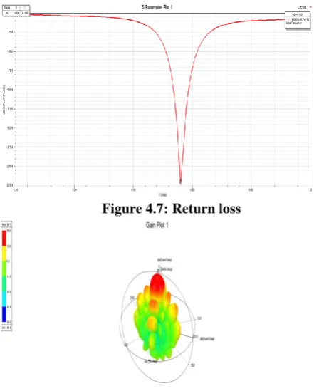
[image:5.595.317.537.387.677.2]Figure 4.7: Return loss
Figure 4.8: 3D Radiation pattern
[image:6.595.310.550.51.724.2]B. Isolation Between Two Antenna Arrays Results
Figure 4.9: Return loss of 2x2 antenna with a distance of 1.5 λ
Figure 4.10: Isolation of 2x2 antenna with a distance of 1.5 λ
Figure 4.11: Return loss of 2x2 antenna with a distance of 2λ
Figure 4.12: Isolation of 2x2 antenna with a distance of 2 λ
Figure 4.13: Return loss of 2x2 antenna with a distance of 2.5 λ
[image:6.595.49.292.361.711.2]Figure 4.15: Return loss of 4x4 antenna with a distance of 1.5 λ
Figure 4.16 Isolation of 4x4 antenna with a distance of 1.5 λ
Figure 4.17 Return loss of 4x4 antenna with a distance of 2λ
Figure 4.18 Isolation of 4x4 antenna with a distance of 2 λ
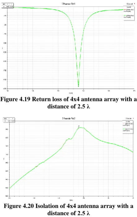
Figure 4.19 Return loss of 4x4 antenna array with a distance of 2.5 λ
[image:7.595.58.297.47.777.2]
Figure 4.20 Isolation of 4x4 antenna array with a distance of 2.5 λ
TABLE.3: Specifications of Single, 1X4, 2X2 and 4X4 Microstrip patch array antenna
Parameters
Single Rectan gular patch
1x4 Rectang ular patch
2x2 Rectangul ar patch
4x4 Recta ngular patch
Return loss -22.417 -19.906 -72.5555 -22.40
52
VSWR 1.3177 1.7620 0.0041 0.1274
Bandwidth MHZ(at-15d B)
20 20 20 20
3dB beam
width(deg)
72.034 15.639 29.8760 15.746
1
Directivity 6.9981 14.576 14.7392 20.802
4
[image:7.595.318.538.414.655.2]The 4x4 array the maximum directivity is 20.8024dBi, return loss of -22.4052 and beam width of 15.7461 deg. That satisfies for bi-static radar applications
TABLE.4: Specifications of isolation for 2X2 and 4X4 patch antenna arrays
Parameters 2x2 4x4
Return loss(S11) (1.5 λ)
-31.0772 -22.4658
Isolation (1.5 λ) -42.7525 -55.5585
Return loss(S11) (2λ)
-29.0076 -22.6384
Isolation (2 λ) -46.0818 -56.938
Return loss(S11) (2.5 λ)
-31.4904 -22.0590
Isolation (2.5 λ) -49.2972 -59.2617
V.CONCLUSION
The microstrip patch array antenna is constructed by using coaxial probe feed for radar applications. The various specifications such as return loss, VSWR, bandwidth, directivity of arrays is simulated using HFSS and to check the isolation for bi-static radar. As the sum of arrays are developed the directivity also increases and distance between two antennas increases the isolation is also increases for which are suitable for bi-static radar.
REFERENCES
1. Kai Fong Lee, Kwai Man Luk, "Microstrip Patch Antennas" Published by Imperical college press.
2. Constantine A. Balanis, "Antenna Theory"- analysis and design, third edition, A John Wiley and sons, Inc., publications.
3. Karishma Patkar, Anshul Agarwal, Neelesh Dixit, "Analysis of Different Shapes of Microstrip Patch Antenna at 1.5GHz", 2016 Symposium on Colossal Data Analysis and Networking (CDAN), pp 1-4, ISBN 978-1- 5090-0669-4, issue on 19 September 2014.
4. Vasujadevi Midasala, Dr. P. Siddaiah," Microstrip Patch Antenna Array Design to Improve Better Gains", International Conference on Computational Modeling and Security (CMS 2016), pp 401-409, Procedia Computer Science 85(2016) published by Elsevier. 5. G. M. Qubati and N. I. Dib, “Microstrip Patch Antenna Optimization using Modified Central Force Optimization”, Progress In electromagnetic Research B, Vol. 21, 281-298, 2010.
6. Bahl, I.J. and Bhartia, P., Microstrip Antennas, Chapter 7, Artech House, Dedham, Mass., 1980.
AUTHORSPROFILE
B. SIVA SAI REDDY currently pursuing Master of
Technology in Digital Electronics and Communication Systems from Sree Vidyanikethan Engineering College Tirupati and his research interests includes on Embedded systems, IoT and Communication based Education, and he is a member of IAE.
P.PARVATHI Scientist/Engineer-SE,
National Atmospheric Research Laboratory, Gadanki, Tirupati, Andhra Pradesh, India.
B. SENTHIL KUMAR currently working as
Associative Professor of Electronics and Communication Engineering in Sree