International Journal of Innovative Technology and Exploring Engineering (IJITEE)
ISSN: 2278-3075, Volume-8 Issue-11, September 2019
Behavior of Piles with Raft Foundation using Safe
Software
Reshma T.V, Bhavya B S, Rashmi Mishra, Sankalpasri S S
Abstract: Piles with raft foundation are a hybrid type of foundation in which the loads coming from the super structure is partly shared by the raft foundation and partly by the piles. A G+20 Storey building is analysed and designed in ETABS software. The modelling and analysis of piles with raft foundation is done in SAFE Software by importing the building loads. The storey drift and story displacement of the structure has been studied for the superstructure loads using response spectrum analysis and time history analysis in both X and Y axes. Then behavior of piles with Raft foundation is studied in this work by considering different parameters. The Pile diameter, Spacing of piles, Number of piles, and raft thickness are varied and keeping height of the pile as constant, the behavior of pile with raft foundation is determined. Pile with Raft foundation is economical when compared to a single pile foundation or Raft foundation. In the present work of piled with raft foundation, the load is shared between pile and raft. Hence Soil settlement is gradually reduced when the piles are introduced below the raft. Finally the optimum dimensions of pile diameter and thickness of the raft are obtained for minimum settlement.
Keywords: Piles with Raft foundation, Response Spectrum, Time History, Settlement.
I.
INTRODUCTION
The Foundation is the function to transmit the burden load
coming from the superstructure must be transferred to the
subsoil by way of presenting safety, reliability, and
serviceability to the structure. Now the existing thesis work
is to offer deep foundation when the shallow foundation is
insufficient to provide adequate safety. However the
combination of the shallow foundation and deep foundation
can be a cost effective design approach. The pile and raft
foundation is such a combination of a deep pile and a
shallow raft foundation.
Raft foundation is a structure which supports the number of
columns in rows and transmits the total load coming from
the superstructure to the subsoil by means of a continuous
slab. The raft foundation reduces the
Differential settlement and often the raft foundation is
required in soft soil as they can spread the loads over a large
area. In the design of foundations, shallow f0undation is the
first option where the t0psoil has sufficient bearing strength
to carry the superstructure l0ad without any significant total
and differential settlements t0 prevent damage 0f
infrastructure and superstructure.
A Pile is a long cylindrical strong material made up of
Concrete, Steel,
Revised Manuscript Received on September 03, 2019
Reshma T.V, Assistant Professor, Department of Civil Engineering,REVA University, Kattigenahalli, Yelahanka, Bangalore, Karnataka, India-560064,
Bhavya B S, Assistant Professor, Department of Civil Engineering,MVJ College of Engineering, Whitefield, Bangalore, Karnataka, India-560067,
Rashmi Mishra, Assistant Professor, Department of Civil Engineering,REVA University, Kattigenahalli, Yelahanka, Bangalore, Karnataka, India-560064,
Sankalpasri S S, Assistant Professor, Department of Civil Engineering,REVA University, Kattigenahalli, Yelahanka, Bangalore,
And timber driven into the ground to support the excessive
loads coming from the superstructure. Pile foundations are
probably taking higher loads comparing to spread OR mat
foundations. To carry the excessive loads that come from
the superstructures like high-rise buildings, bridges, power
plants or other civil structures and to prevent excessive
settlements, piled foundations have been developed and
widely used in recent decades. However, it is observed that
the design of foundations considering only the pile or raft is
not a feasible solution because of the load sharing
mechanism of the pile-raft-soil. Therefore, the combination
of two separate systems, namely “Piled Raft Foundations”
has been developed (Clancy and Randolph (1993)).
Fig.1 Piles with Raft Foundation
II.
METHOD OF MODELING AND ANALYSIS
To examine the behavior of piled raft foundation Etabs 2013
and safe 2012 is used. First Investigation of the site location
is done where the bearing capacity of soil is poor and taking
the SBC of soil in that area and basic tests are carried out to
study the properties of the soil. Using Etabs software the 25
storey building is analysed and designed by taking the super
structure loads
Using the safe software the piled raft foundation is modelled
and taking the results of piled raft foundation and finally
Optimum combination of pile and raft dimensions is
selected.
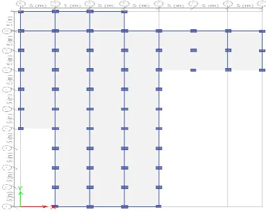
Fig. 1 Plan of building
Table. 1: List of Sections Properties of Columns, Beams &
Slabs
No. Column in mm Beams in mm Slabs in mm
[image:2.595.59.533.61.753.2]1 600 × 750 300 × 450 200 2 750 × 900 450 × 600 200
Fig.3. 3D Model of the building
Table 2: Loads on building assigned
Live Load As per IS – 875
Part 2
4 KN/m²
Wall Thickness
200mm
Wall load
10.2 kN/m²
Floor Finish
1.5 kN/m²
B. Piled raft foundation in safe software
Fig 4.Assignments of piles as pile springs
C. Calculation of pile springs K
Stiffness of the column K=
Where E=young’s modulus of concrete
A=Area of the pile
L=Length of the pile
Length of the pile taken=15m
III.
PARAMETERS CONSIDERED TO STUDY
THE BEHAVIOR OF PILED RAFT
FOUNDATION
A. Geometrical properties of the Piled raft foundation
model is given below:
1.
Height = 62m
2.
Building plan = 35 × 50 m
3.
Length of piles = 15m
B. Different combination of piled raft foundation:
IV.
RESULTS AND DISCUSSIONS
A. Response Spectrum Analysis
[image:2.595.345.512.473.643.2]International Journal of Innovative Technology and Exploring Engineering (IJITEE)
ISSN: 2278-3075, Volume-8 Issue-11, September 2019
Fig. 5 Storey Displacement along X and Y Direction for
Response Spectrum Method
[image:3.595.310.537.72.227.2]Storey Drift
Fig.6 Storey drift along X & Y direction for response
spectrum method
B. Time History Analysis
Storey Displacement
Fig.7 Storey drift along X & Y direction for response
spectrum method
Storey Drift
Fig.8 Storey drift along X & Y direction for response
spectrum method
C. Raft Foundation Settlement
Fig.9 single Raft soil settlement
As per the analysis of the soil report the soil permissible
settlement of the foundation is 5mm to 10mm. Actual
settlement of raft is much more than the permissible limit.
Hence it is necessary to provide piles below the raft to
reduce the settlement.
To control the settlement of the raft, pile foundation is
introducing below the raft at 15m depth and to know the
behavior of piles and raft the parameters of the piles and raft
are varied depending upon the parameter the optimum one is
verified.
D. Pile Diameter 600mm
[image:3.595.56.280.250.410.2]Pile diameter 600mm and raft thickness 750mm
Fig.10 Piled with raft foundation settlement with pile dia
600mm & raft thickness 750mm
Pile diameter 600mm and Raft thickness 900mm
Fig.11 Piled with raft foundation settlement with pile dia
600mm & raft thickness 900mm
Pile diameter 600mm and Raft thickness 1200mm
0
20
40
60
80
0
50
100
STOREY DISPLAC EMENT X
DISPLACEMENT IN MM
B
U
IL
D
IN
G
H
EI
G
H
T
I
N
M
0
20
40
60
80
0
0.001
0.002
STO…
H
EI
G
H
T
IN
M
M
STOREY DRIFT
-4 -3 -2 -1 0
0 500 1000 1500 2000
MAXIMUM SOIL SETTLEMENT
MAXIMUM SOIL SETTLEMENT
LOAD IN KN
D
IS
P
L
A
C
EM
EN
T
I
N
MM
-3 -2 -1 0
0 500 1000 1500
MAXIMUM SOIL SETTLEMENT
MAXIMUM SOIL
SETTLEMENT LOAD IN KN
D
IS
P
L
A
C
EM
EN
T
I
N
[image:3.595.308.541.398.516.2] [image:3.595.305.528.573.675.2]Fig.13 Piled with raft foundation settlement with pile dia
600mm & raft thickness 1200mm
E. Pile Diameter 800mm
Pile diameter 800mm and raft thickness 750mm
Fig.14 Piled with raft foundation settlement with pile dia
800mm & raft thickness 750mm
Pile diameter 800mm and Raft thickness 900mm
Fig.15 Piled with raft foundation settlement with pile dia
800mm & raft thickness 900mm
Pile diameter 600mm and Raft thickness 1200mm
Fig.16 Piled with raft foundation settlement with pile dia
800mm & raft thickness 1200mm
F. Pile Diameter 1200mm
Pile diameter 1000mm and raft thickness 750mm
Fig.17 Piled with raft foundation settlement with pile dia
1000mm & raft thickness 750mm
Pile diameter 600mm and Raft thickness 900mm
Fig.18 Piled with raft foundation settlement with pile dia
1000mm & raft thickness 900mm
Pile diameter 1000mm and Raft thickness 1200mm
Fig.20 Piled with raft foundation settlement with pile dia
1000mm & raft thickness 1200mm
Table.4 Maximum and Minimum settlement of Pile with
Raft foundation
SL .N O. Pile diameter in mm Raft Thickness in mm Maximum settlement in mm Minimum Settlement in mm750 3 0.485
1 600 900 2.5 0.5
1200 2.4 0.61
750 2.7 0.2
2 800 900 2.45 0.3
1200 2.2 0.145 750 2.6 0.1104
3 1000 900 2.4 0.10
1200 2.1 0.1
V.
CONCLUSION
Pile with Raft foundation is economical when compared to a
single pile foundation or Raft foundation.In the present work
piled with raft foundation, the load sharing of pile and raft
results in gradual reduction of soil settelement when the
piles are introduced below
the raft.
-3-2 -1 0
0 500 1000 1500
MAXIMUM SOIL SETTLEMENT
MAXIMUM SOIL
SETTLEMENT LOAD IN KN
D IS P L A C EM EN T I N MM -3 -2 -1 0
0 1000 2000 3000
MAXIMUM SOIL SETTLEMENT
MA…
LOAD IN KN
D IS P L A C EM EN T I N M M -3 -2 -1 0
0 1000 2000 3000
MAXIMUM SOIL SETTLEMENT
MAXIMUM SOIL SETTLEMEN T
LOAD IN KN
D IS P L A C EM EN T IN M M -3 -2 -1 0
0 1000 2000 3000
MAXIMUM SOIL SETTLEMENT
MAXIMUM SOIL
SETTLEMENT LOAD IN KN
D IS P L A C EM EN T I N M M -3 -2 -1 0
0 1000 2000 3000 4000
MAXIMUM SOIL SETTLEMENT
MAXIMUM SOIL SETTLEMENT
LOAD IN KN
D IS P L A C EM E N T I N M M -3 -2 -1 0
0 2000 4000
MAXIMUM SOIL SETTLEMENT
MAXIMUM SOIL SETTLEMEN T
LOAD IN KN
D IS P L A C EM EN T I N M M
-3
-2
-1
0
0
1000 2000 3000 4000
MAXIMUM SOIL SETTLEMENTMAXIMUM SOIL
SETTLEMENT LOAD IN KN
International Journal of Innovative Technology and Exploring Engineering (IJITEE)
ISSN: 2278-3075, Volume-8 Issue-11, September 2019
From this study, the following conclusions can be made
From the above study it was found that the maximum soil
settlement was reached to 5.67mm using 600mm pile
diameter and 750mm raft thickness.
On increasing the diameter of piles, the number of piles
also be varied and hence load carrying capacity of the
piles increases and settlement of the soil will be
decreased.
Use of 1000mm pile diameter and 1200mm raft thickness
lead to reduction of soil settlement to 3mm.
Finally optimum size for the piled with raft foundation to
be used in silty clayey soil is obtained as 1000mm pile
diameter with 1200mm raft thickness.
REFERENCES
1. IS 456:2000, “Plain and Reinforced Concrete –Code of Practice”, ISI New Delhi,2000
2. IS 1893 part 1, “Criteria for Earthquake Resistant Design Of Structures, General Provisions and Buildings”, BIS, New Delhi, 2002. 3. IS 2911 : PART 1 “Code of Practice for driven Cast in-Situ Concrete
Piles”
4. Padmanaban M S, J Sreerambabu, “Issues on Design of Piled Raft foundation” Volume. 14 December 2017
5. Rahul Solanki, Sagar Sorte, “A Review of Piled Raft Foundation”, ISSN 2278-3652 Volume 7, 2016
6. Dinachidinandra Thoidingjam, D S V Prasad, Dr. K.Rambha Devi, “Effect of Number of pile Raft system in organic clay” IOSR Volume 13 (Jul-Aug.2016).
7. Emilios M Comodromos, Mello C Papadopoulou and Ioannis K Rentzeperis (2009), “Pile Foundation Analysis and Design Using Experimental Data And 3-D Numerical Analysis”, Science direct Computers and Geotechnics, Vol. 36 , pp. 819-836.
8. Dang Dinh Chung Nguyen, Seong-Bae Jo and Dong-Soo Kim (2013), “Design Method of Piled-Raft Foundations under Vertical Load Considering Interaction Effects”, Science direct- Computers and Geotechnics, Vol. 47, pp. 16-27.
9. Poulos, H.G (2001) small, J.C,. & Chow, H (2011) “Piled Raft Foundation for Tall Buildings”, 42(June), 78-84.
10. Solanki CH, Vasanvala SA, Patil JD. A study of piled raft foundation: state of art. Int J Eng Res Technol (IJERT) 2013;2(8);1464-70.
AUTHORS PROFILE
Ms. Reshma T V, Assistant Professor, School of Civil Engineering, REVA University, Bengaluru, holds M.Tech degree in Structural Engineering and B.E. degree in Civil Engineering from VTU . I have 4 years of experience in teaching and research. My research interests are in the areas of Concrete technology, Earthquake resistant structures and Optimization Techniques. I have 2 International publication and presented 3 technical paper in International conference. I have received Best student of the batch award during Engineering.
Mrs. Bhavya B S, Assistant Professor, School of Civil Engineering, MVJ College of Engineering, Bengaluru, holds M.Tech degree in Structural Engineering from Calicut University and BTech in Civil Engineering from Anna University. I have around 4 years of experience in teaching and industry. My research interests are in the areas of Concrete technology, Earthquake resistant structures. I have 2 International publication and presented 4 technical paper in International conference. I have received 3 IET awards in 2013
Mrs. Rashmi Mishra, Assistant Professor, School of Civil Engineering, REVA University, Bengaluru, holds M.Tech degree in Structural Engineering from NITR and BTech in Civil Engineering from Biju Patnaik University of Technology, Odisha . I have 5 years of experience in teaching and industry. My research interests are in the
control of structures, Construction Technology, Structural health monitoring. I have 2 International publication and presented 2 technical paper in International conference.