International Journal of Innovative Technology and Exploring Engineering (IJITEE) ISSN: 2278-3075, Volume-8 Issue-8 June, 2019
Abstract: Twin Rotor Multi-input-multi-output System (TRMS) resembles a desktop version of a non-linear helicopter model. It consists of two rotors namely tail rotor and main rotor. A model based on first principle modeling approach is designed in MATLAB Simulink environment. An adaptive control scheme based on Model Reference Adaptive Systems (MRAS) theory is implemented for tracking the desired trajectory with changing system parameters and disturbances. MRAC based Lyapunov Theory is used to adjust the gains for guaranteeing stability and converges the error to zero under stochastic conditions. The output of the TRMS Model is far better for MRAC based Lyapunov Approach than compared to PID. The main objective of this project is to stabilize the non-linear TRMS model.
Index Terms: Helicopter model, Lyapunov Approach, MRAC, PID control, TRMS.
I. INTRODUCTION
TRMS Systems, [1, 2], are generally non-linear, unstable and time varying systems. The effort made by any controller is to move the system’s beam accurately to settle in the desired altitudes in terms of PITCH and YAW angles. It is very difficult to design a controller for this system due to its high non linearity. Various control techniques have been proposed to optimize the performance of the system [3 -5]. A PID control scheme with a derivative filter is developed for this system by considering two SISO systems. It is used to make decisions of changing the control signal that is used to drive the plant output. Each and every type of controller has a large effect on changing the system output. A proportional controller multiplies a small amount of constant gain value to the error. The static steady state error is reduced by using an integral action of the controller. A derivative controller is used to stabilize the loops by adding a phase shift and reducing the maximum peak overshoot. The main disadvantage of this PID controller is that a constant set of gain values are not present for the controller as the controller parameters depends on the physical characteristics of the system. These parameters dynamically change with respect to time. As it is a non-linear system there are many system parameter variations and process changes so, an adaptive controller handles changes in system dynamics and copes up with system uncertainties. These adaptive controllers are used to solve many real life problems such as robot control, flight control and process control problems. Adaptive control techniques such as Gain scheduling controllers, M0del
Revised Manuscript Received on June 05, 2019
G. Shivani, School of Electrical Engineering, VIT, Vellore, India. Anuja E. Jamodkar, School of Electrical Engineering, VIT, Vellore, India.
B. Jaganatha Pandian, School of Electrical Engineering, VIT, Vellore, India.
reference adaptive controller using MIT rule and MRAC based Lyapunov Approach are used to stabilize the system output. In this paper MRAC based Lyapunov Approach is used to create a closed loop controller to adjust the parameters based on deviation of the system output from the output of a reference model and output. In this control technique the system response is expected to follow the reference model response by resulting.
II. MODELLINGOFTRMSSYSTEM The TRMS system consists of two rotors namely main rotor and tail rotor. There are two outputs of the system elevation output and azimuth output of the system. First principle modelling is used to derive the parameters of the system. It can be done for one DOF and two DOF. In this paper controllers are designed for a one DOF system by spliting the model as horizontal and vertical plane parts. The TRMS is driven by two permanent magnet DC motors, which are scheduled to act as main motor and tail motor. The modeling equations of the PMDC motor are given in equation (1):
( , )
( , )
(
, ). ( , )
(
, )
( )
1
(1)
( )
( , )
( , )
J(
, ).
(
, ). ( , )
a a r r a a r r
e r r r r
di v h
U v h
R m t
i v h
L m t
dt
I s
V s
Ls
R
d
v h
T v h
m t
B m t
v h
dt
Here,
U (v, h) – voltage input for vertical and horizontal control of the system
Ra (mr, tr) – armature resistance ia (v, h) – armature current La (mr, tr) – armature inductance Te (v, h) – electromagnetic torque. J (mr, tr) – moment of inertia of rotor. B (mr, tr) – damping coefficient of rotor. Ω (v, h) – rotation velocity.
For modeling the TRMS system, the vertical and horizontal movements are individually considered [6, 7] in this work. Fig.1 and Fig.2 shows the individual models used in this work and their corresponding model equations are given in equation (2).
Modeling and Implementation of Adaptive
Control Technique on a TRMS Model
Fig. 1: Model for vertical part of TRMS 6 1 5 1 5 1 5 1
(I )
{p1(i) * I }
(
)
{p 2(i) *
}
(
)
{p 4(i) *
}
(I )
{p 3(i) * I }
i
v v v
i
i
v m v
i
i
h t t
i
i
h h h
i
F
F
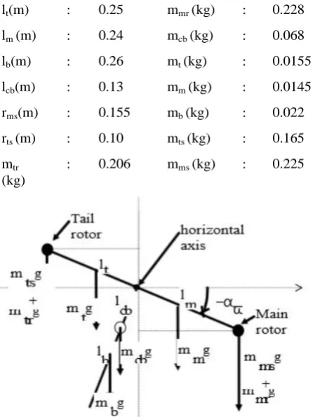
(2)Fig. 2 : Model for horizontal part of TRMS System The physical parameters of the TRMS System, as in Fig.3, considered for simulation are given below:
lt(m) : 0.25 mmr (kg) : 0.228
lm (m) : 0.24 mcb (kg) : 0.068
lb(m) : 0.26 mt (kg) : 0.0155
lcb(m) : 0.13 mm (kg) : 0.0145
rms(m) : 0.155 mb (kg) : 0.022
rts (m) : 0.10 mts (kg) : 0.165
mtr (kg)
[image:2.595.48.291.55.336.2]: 0.206 mms (kg) : 0.225
Fig. 3: Free body representation of TRMS system
[image:2.595.50.277.399.701.2]Model of the TRMS System’s moving part models are obtained using the Newton’s second law for rotational motion.
Fig. 4. Forces on TRMS for vertical plane A. Vertical Plane:
The forces acting with respect to the vertical plane are shown in Fig.4 and they are mathematically represented in equations (3) and (4).
1 2 3 4
v
v v v v v
ds
M
M
M
M
M
dt
(3)Where M = Torque
S = Angular Momentum
Mv1 =Total torque due to Gravity: = g * [(A-B) cosαv – C sinαv]
Mv2 = Moment of Thrust(Propulsive forces) applied to beam = [lm * Fv ( m)]
Mv3 = Moment of Centrifugal forces (correspond to beam’s movement around vertical-axis)
= [-Ωℎ 2 {(A+B+C) sinαv cosαv} ]
Mv4 = Moment of Friction (depend on horizontal angular velocity of beam) = ( Ωv kv)
The equivalent Torque on vertical plane is given in (4):
2
(
)
(
) cos(
)
sin(
)
1
(
) sin(2
)
2
,
2
(4)
2
2
m v m v v v v
h v
v
v
t ts tr t
m mr ms m
cb cb b b
l F
k
g
A B
C
A
B C
ds
dt
J
here
m
A
m
m
l
m
B
m
m
l
l
C
m l
m
[image:2.595.51.276.400.698.2]International Journal of Innovative Technology and Exploring Engineering (IJITEE) ISSN: 2278-3075, Volume-8 Issue-8 June, 2019
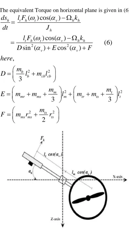
B. Horizontal Plane:
Various forces acting on TRMS system, considering the horizontal plane, are shown in Fig.5. The corresponding modelling equations are given in (5) and (6).
1 2
(5)
h
h h h
ds
M
M
M
dt
Mh1 = Moment of Thrust(Propulsive forces) applied to beam {Fh (wt) * lt * cos }
Mh2 = Moment of Friction (depend on the vertical angular velocity of the beam).
(Ωh kh)
The equivalent Torque on horizontal plane is given in (6):
2 2
2 2
2 2
2 2
(
) cos(
)
(
) cos(
)
(6)
sin (
)
cos (
)
,
3
3
3
2
h t h t v h h h
t h t v h h
v v
b
b cb cb
m t
mr ms m tr ts t ts
ms ms ts
ds
l F
k
dt
J
l F
k
D
E
F
here
m
D
l
m l
m
m
E
m
m
l
m
m
l
m
F
m r
r
[image:3.595.48.273.199.600.2]
Fig. 5. Forces on TRMS for horizontal plane C. Inertia Calculation:
The total inertia for vertical and horizontal planes can be computed using (7) and (8) respectively:
8
1
2 2
2 2 2 2
(7)
3
3
3
2
v vi i m tmr ms m tr ts t
b ms
b cb cb ts ts ms
J
J
m
m
m
m
l
m
m
l
m
m
l
m l
m r
r
8 2 2 1sin (
)
cos (
)
(8)
h hi v v
i
J
J
D
E
F
III. MRACBASEDLYAPUNOVAPPROACH Model Reference Adaptive Control, shown in Fig.6, is one of the main approaches of Adaptive Control Theory. The system performance should be same as that of the reference model output. When the behavior of the controlled process differs from that of the reference model behavior the process is modified by adjusting the parameters of the controller based on the error generated between reference model and plant model. There are two loops in the MRAC: one is primary loop and the other is secondary loop.
[image:3.595.310.551.272.389.2]The primary loop provides ordinary feedback control mechanism. The secondary loop adjusts the parameters in the primary loop. The primary loop is faster than secondary loop.
Fig. 6. Block Diagram of Direct MRAC
MRAC – MIT Rule is the one basic techniques of adaptive control. The disadvantage of MIT Rule is that it does not guarantee the stability of closed loop system. MRAC based Lyapunov Approach results in closed loop stability.
MRAC can be classified into two classes: 1. Indirect Adaptive Control 2. Direct Adaptive Control
In Direct Adaptive control system the output of the TRMS System follows the second process which is controlled. In this paper Direct MRAC based Lyapunov Approach is used.
IV. IMPLEMENTATION A. PID IMPLEMENTATION
(a)
(b)
Fig. 7. (a) Controller simulation and (b) Model of vertical part of TRMS (main rotor)
(a)
(b)
Fig. 8. (a) Controller simulation and (b). Model of horizontal part of TRMS (tail rotor) B. MRAC IMPLEMENTATION
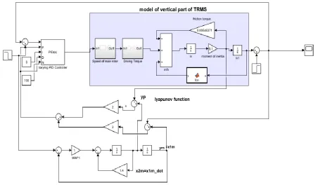
[image:4.595.73.547.49.283.2]Simulation of MRAC controllers for individually controlling the vertical and horizontal movement of the TRMS are shown in Fig. 9 and Fig. 10 respectively. The MRAC design is based on Lyapunov approach, which also ensures stability.
[image:4.595.54.319.51.291.2] [image:4.595.72.525.391.655.2]International Journal of Innovative Technology and Exploring Engineering (IJITEE) ISSN: 2278-3075, Volume-8 Issue-8 June, 2019
Fig. 10.Horizontal part of TRMS (tail rotor) with MRAC Based on Lyapunov approach V. SIMULATIONRESULTS
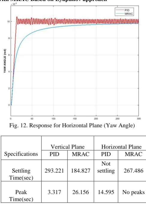
[image:5.595.93.513.55.329.2]In this work, a TRMS model with one DOF is used for studying a MRAC control approach. PID controller and MRAC based on Lyapunov approach have been imposed on horizontal and vertical subsystems of TRMS system to control the system movements individually. The system response under the PID controller in comparison with MRAC is presented in this section. Fig.11. shows the response of TRMS system in vertical plane using two controllers PID and MRAC. Whereas Fig.12. shows the response of TRMS system in horizontal plane using two controllers PID and MRAC. The time domain performance of tested controllers are compared in Table.I.
[image:5.595.306.550.351.691.2]Fig. 11. Response for Vertical Plane (Pitch Angle)
Fig. 12. Response for Horizontal Plane (Yaw Angle)
Specifications
Vertical Plane Horizontal Plane
PID MRAC PID MRAC
Settling Time(sec)
293.221 184.827 Not
settling 267.486
Peak Time(sec)
[image:5.595.55.283.536.737.2]3.317 26.156 14.595 No peaks
VI. CONCLUSION
In this paper, an adaptive control scheme based on Model Reference Adaptive Systems (MRAS) theory was implemented for tracking the desired trajectory with changing system parameters and disturbances. Equations (1)-(8) are used to model the TRMS Model System. By using MRAC based Lyapunov Theory, the gains were adjusted to get the guaranteed stability and the error obtained converges to zero under stochastic conditions. It is seen that the output of the TRMS Model obtained is far better for MRAC based Lyapunov approach than compared to PID controller because it settles at a faster rate.
REFERENCES
1. Feedback Instrument Ltd., Twin Rotor MIMO System 33-007-4M5 user manual.
2. Feedback Instrument Ltd., Twin Rotor MIMO System 33-007-2M5 user manual.
3. Lih-Gau luang, Wen-Kai Liu, Cheng-Yu Tsai, “Intelligent Control Scheme for Twin Rotor MIMO System”, Proceedings of the 2005 IEEE Internat ional Conference on Mechat ronics July 10-12. 2005, Taipei, Taiwan.
4. Nguyen Duy Cuong and Horst Puta. "Design of MRAS based control systems for load sharing of two DC motors with a common stiff shaft", 2013 International Conference on Control Automation and Information Sciences (ICCAIS), 2013.
5. Mohammed Moness, Ahmed M Mostafa. "An algorithm for parameter estimation of twin rotor multi-input multi-output system using trust region optimization methods", Proceedings of the Institution of Mechanical Engineers, Part I: Journal of Systems and Control Engineering, 2013.
6. Patel, Akash A., Prakash M. Pithadiya, and Hardik V. Kannad. "Control of twin rotor mimo system (trms) using pid controller." National Conference on Emerging Trends in Computer, Electrical & Electronics (ETCEE2015) International Journal of Advance Engineering and Research Development (IJAERD) e-ISSN. 2015.
7. Chalupa, Petr, Jan Přikryl, and Jakub Novák. "Modelling of twin rotor MIMO system." Procedia Engineering 100 (2015): 249-258.
AUTHORSPROFILE
G. Shivani, currently persuing her M.Tech degree in control and automation from School of Electrical Engineering, VIT, Vellore, India. Her research interest includes Adaptive control and Optimal control.
Anuja E. Jamodkar, currently persuing her M.Tech degree in control and automation from School of Electrical Engineering, VIT, Vellore, India. Her research interest includes Adaptive control and Smart automation.