UNIVERSITI TEKNIKAL MALAYSIA MELAKA
DESIGN OF FUZZY-PID CONTROLLER FOR TRACKING
PERFORMANCE OF MACHINE TOOL
This report submitted in accordance with requirement of the Universiti Teknikal Malaysia Melaka (UTeM) for the Bachelor Degree of Manufacturing Engineering
(Department of Robotics and Automation) (Hons)
By
NABILAH BINTI HALIM B051210230
930126145442
i
DECLARATION
I hereby, declared this report entitled “Design of Fuzzy-PID Controller For Tracking
Performance of Machine Tool” is the results of my own research except as cited in references.
Signature : ………
Author‟s Name : Nabilah Binti Halim
ii
APPROVAL
This report is submitted to the Faculty of Manufacturing Engineering of UTeM as a partial fulfillment of the requirements for the degree of Bachelor of Manufacturing Engineering (Robotics and Automation) (Hons). The member of the supervisory is as follow:
………
iii
ABSTRAK
iv
ABSTRACT
v
DEDICATION
vi
ACKNOWLEDGEMENT
First and foremost, all praise to the Almighty, who made this accomplishment possible. I seek his mercy favor and forgiveness.
Thousands of thank to my great supervisor, Ir.Dr Lokman bin Abdullah for the help, encouragement and guidance from the beginning until end of this writing project. Thousands of thank also to Dr. Syed Najib as a co-supervisor that had a lot things share together.
For my parents, Halim bin Mustaffa and Norbahani binti Subari and my family who are always provides me with love and support all the time in order for me to complete this work. Their enthusiastic caring is valuable for me.
My thanks and appreciations also go to my colleagues in developing the project and people who have willingly helped me out with their abilities.
vii
TABLE OF CONTENT
Abstrak i
Abstract ii
Dedication iii
Acknowledgement iv
Table of Content v
List of Tables viii
List of Figures ix
List Abbreviations, Symbols and Nomenclatures xi
CHAPTER 1: INTRODUCTION 1
1.1 Background 1
1.2 Problem Statement 2
1.3 Objective 3
1.4 Scope of Work 3
viii
CHAPTER 2: LITERATURE REVIEW 5
2.1 Introduction 5
2.2 Motion Control in Machine Tool 6
2.2.1 Mechanical Drive System 6
2.3 A Controller Design Approach 10
2.3.1 Controller Design 10
2.3.2 PID Controller 10
2.3.3 Fuzzy-PID Controller 11
2.4 Summary 12
CHAPTER 3: METHODOLOGY 13
3.1 Introduction 13
3.2 Experimental Setup 16
3.3 Software Requirement 18
3.4 System Identification and System Modeling 18
3.5 Motor Constant Identification 20
3.6 Summary 21
CHAPTER 4: RESULTS AND DISCUSSIONS 22
4.1 Introduction 22
ix 4.2.1 General Structure and Configuration of PID Controller 23 4.2.2 Design and Analysis of PID Controller 25
4.3 Fuzzy-Logic Controller 29
4.3.1 Rule Base 31
4.3.2 Design and Analysis of the Fuzzy-PID Controller based on Measured
FRF 37
4.4 Maximum Tracking Error 39
4.4.1 Sinusoidal Input 40
4.4.1.1 Simulation of PID Controller 40 4.4.1.2 Simulation of Fuzzy-PID Controller 43
4.4.2 Step Input 47
4.4.2.1 Simulation of PID Controller 48 4.4.2.2 Simulation of Fuzzy-PID Controller 49
4.5 Root Mean Square Error (RMSE) 50
CHAPTER 5: CONCLUSION AND RECOMMENDATION FOR FUTURE
IMPROVEMENT. 51
5.1 Conclusion 51
5.2 Recommendation for Future Improvement 54
x
LIST OF TABLES
3.1 System Model Parameter for X-axis 10
4.1 Gain Values of PID Controller for X-axis 14 4.2 Rule of Thumb Gain Margin and Phase Margin 15 4.3 Gain Margin and Phase Margin of Open Loop Position 16
4.4 The Control Rules of Kp 32
4.5 The Control Rule of Ki 32
4.6 The Control Rule of Kd 33
4.7 Fuzzy-PID Controller for X-axis 37
4.8 Comparison of MAXIMUM Tracking Error of Sinusoidal Input 46 4.9 Result of Transient Response for PID Controller 48 4.10 Result of Transient Response for Fuzzy-PID Controller 49 4.11 Comparison of RMSE of Simulation for Both Controllers 50
xi
LIST OF FIGURES
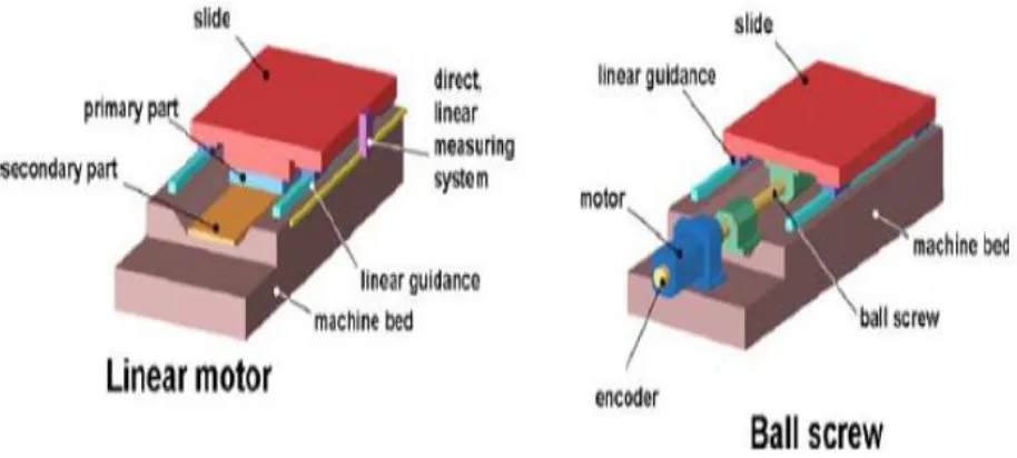
2.1 Linear and Ball Screw Drive System 7
2.2 Rack and Pinion Drive System 7
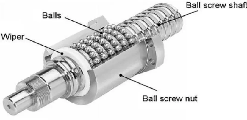
2.3 Structure of Ball Screw System 9
2.4 Ball Screw Drive System 9
3.1 Flowchart of the project Methodology 15 3.2 Gogol Tech XYZ Table Ball Screw Drive System 16 3.3 Schematic diagram of the experimental setup 17 3.4 FRF Measurement and Proposed Model 19
4.1 Control Structure of PID Control 24
xii 4.9 Bode Magnitude Diagram of Sensitivity when the Magnitude is -3dB 38 4.10 Bode Magnitude Diagram of Sensitivity at Peak Response 39 4.11 Simulation Diagram for PID Controller in Simulink 41 4.12 Simulated Tracking Error for Disturbance Forces at 1500N 41 4.13 Simulated Tracking Error for Disturbance Force at 2500N 42 4.14 Simulated Tracking Error for Disturbance Force at 3500N 42 4.15 Simulation Diagram for Fuzzy-PID Controller in Simulink 43 4.16 Simulation Diagram inside the PID_Subsystem 43 4.17 Simulated Tracking Error for Disturbance Forces at 1500N 44 4.18 Simulated Tracking Error for Disturbance Forces at 2500N 44 4.19 Simulated Tracking Error for Disturbance Forces at 3500N 45 4.20 Simulated Transient Response for PID Controller 47
4.21 Zoom In graph from Figure 4.20 47
4.22 Simulated Transient Response for Fuzzy-PID Controller 48
xiii
LIST OF ABBREVIATIONS, SYMBOLS AND
NOMENCLATURE
P - Proportional I - Integral D - Derivative
SISO - Single-Input-Single-Output GUI - Graphical User Interface FRF - Frequency Response Function LTI - Linear Time Invariant
mm - millimeter
DSP - Digital Signal Processor CNC - Computer Numerical Control RMSE - Root Mean Square Error GM - Gain Margin
PM - Phase Margin dB - Decibels
xiv NS - Negative Small
1
CHAPTER 1
INTRODUCTION
This chapter provides an overview about the project entitled, “Design of Fuzzy-PID Controllers for Tracking Performance of XY Table Ball Screw Drive System. Problem statement, objectives, scopes of work and outline of the project are presented in this chapter.
1.1 Background
2 constraint need to implement into the system which is high accuracy and self-adjusting mechanism. Tracking accuracy is concessional by the effect that comes from the dead zones and the huge friction forces that are generated in a high stiffness electromechanical ball screw and bearing structure.
Fast machining requires rapid situating control of the feed drive system, while its situating exactness and rate decide the machining quality and profitability. Ball screw drives are broadly utilized as the movement mechanism due to their high stiffness and high accuracy. One of the disturbance forces that greatly have an effect on the trailing performance is cutting forces. Cutting forces is that the nature of the edge method and can‟t be avoided because it is generated from the interaction between the cutting tool and also the work piece. In keeping with, cutting force is influenced by the edge parameters like the depth of cut and spindle speed (Chiew, 2012).
1.2 Problem Statement
Nowdays, the demand for top speed and accuracy of machine tools area unit required in machine tools trade. Thus, smart controller style is crucial so as to get good tracking performance of a machine. Unnecessary vibration can cause quality and poor surface quality. The compensation of cutting forces disturbance is desired so as to get smart tracking performance.
3 drive system to run from one position to a different position is that the result of the need. The main problem is to design controllers which are PID and Fuzzy-PID controller with comparison of simulation and experimental in order to obtain an accurate tracking performance of the system. The controller square measure created supported the look analysis wherever embrace the gain margin and phase margin analysis and stability analysis.
1.3 Objective
The objectives of the project are:
i. To perform system identification of plant XYZ Table Ball Screw Drive system ii. To design PID and Fuzzy-PID controller for improvement in tracking
performance via cutting force compensation.
iii. To compare the tracking performance of controllers in terms of maximum tracking error and root mean square error using input sinusoidal and transient response using input step.
1.4 Scope of Work
The scopes of this project are:
4 ii. The axis that involved the XY table ball screw drive system is X-axis only to
improve the tracking performance in a horizontal direction.
iii. The disturbance forces used is cutting force disturbance that only covers 1500rpm, 2500rpm and 3500rpm.
iv. The cutting forces only cover 1500 N, 2500 N and 3500 N of up-milling process. v. Thus the controller is designed by simulation using Simulink of Matlab software. vi. The performance of the controller is determined in term of maximum tracking error, root mean square error (RMSE) for sinusoidal input and transient response for step input.
1.5 Structure of Report
5
CHAPTER 2
LITERATURE REVIEW
2.1 Introduction
Traditional machining processes consist of turning, boring, drilling, reaming, milling, threading, shaping, planning and broaching as well as abrasive processes such as grinding, ultrasonic machining, lapping and honing while advanced processes include electrical and chemical means of material removal as well as the use of abrasive jets, water jets, laser beams and electron beams (Gutowski, 2009). Milling can be defined as a process of removing materials which cover a variety of operations in manufacturing industry.
6 existence disturbance during the process. Thus, the objective of the motion controller is to achieve maximum tracking accuracy and robustness against disturbance. (Jamaludin, 2014)
2.2 Motion Control in Machine Tool
In the manufacturing, machine tool is important as a mechanical system that needed to increase the productivity in the performing at high accuracy. Thus to get the precision in positioning of the system, mechanical drive system is one of the progress inside it. Good machine tools will show the process with high speed of processing, low time consumption and high accuracy.
2.2.1 Mechanical Drive System.
7 Figure 2.1 Linear and Ball Screw Drive System
For rack-pinion-drives system is linear motion of the straight rack of arrangement that converted from rotary motion of the pinion and can be manufactured either in straight spur, helical teeth or bevel and worm (Collins, Busby, & Staab, 2010). Rack-pinion-drives system is suitable for the machine tool with long path distances. This is because at high torque the rack-pinion-drives system can transfer with low revolution (Y. Altintas, 2011). Figure 2.2 shows the movement of rack and pinion in producing linear movement.
[image:22.612.117.534.496.676.2]8 Then, other drive system to be discussed is ball screw drives system that is the common used in feed drives of machine tools. The ball-screw drive is supported by thrust bearings at the two end, and a nut with recirculating balls. The nut is connected to the end of table. One end of the ball-screw is attached to a rotary motor directly or through gear or belt speed reduction mechanism as shown in Figure 2.3. To avoid backlash by adjusting the spacer, creating offset between the leads or using oversized ball, the nuts is preloaded. The pitch errors are existence as position errors accept they are compensated because of the difficulty to grind the pitch at uniform intervals (Altintas et al, 2011). Ball-screw drives are another mechanical system that can be described as rotary motion convert to linear motion, whereas the rotary motion comes from the rotation of the ball screw before the change into linear direction. Figure 2.4 shows the basic structure of the ball screw mechanism.
9 Figure 2.3 Structure of Ball Screw System
[image:24.612.115.536.441.635.2]