AT DIFFERENT IMPLANT POSITIONS - AN IN VITRO STUDY
Dissertation submitted to
THE TAMILNADU DR. M.G.R. MEDICAL UNIVERSITY CHENNAI
In partial fulfillment for the degree of
MASTER OF DENTAL SURGERY
BRANCH - I
ACKNOWLEDGEMENTS
First and foremost, I would like to express my sincere gratitude to my advisor
Dr.VIDYA SANKARI, M.D.S., for her continuous support, patience and motivation. I could not have imagined having a better advisor and mentor for my post-graduation. This
dissertation could not have been completed without her immense knowledge, generous
and professional assistance.
I extend my sincere thanks to our Principal, Dr.G.S.KUMAR, M.D.S., KSR Institute of Dental Science & Research, for the facilities he has provided for the
betterment of the students. I would also like to thank my head of the department
Dr.C.A.MATHEW, M.D.S., and other staff including Dr.MAHESHWARAN, M.D.S.,
Dr.MUTHUVIGNESH, M.D.S., Dr.SURESH KUMAR, M.D.S.,
Dr.VISHWANATHAN, M.D.S., Dr.RAJKUMAR, M.D.S., Dr.RAJAGANESH, M.D.S., and Dr.GOUTHAM, M.D.S., I am so deeply grateful for their help, professionalism and valuable guidance throughout the course.
I would also like to thank the non-teaching staff members in our department and
staff members of the library for their kind cooperation in my career as a post graduate
student.
CONTENTS
S.NO
TITLE
PAGE NO.
1. INTRODUCTION 1
2. STATEMENT OF PROBLEM 3
3. AIMS AND OBJECTIVES 4
4. NULL HYPOTHESIS 5
5. REVIEW OF LITERATURE 6
6. MATERIALS 24
7. METHODOLOGY 27
8. COLOUR PLATES 37
9. RESULTS 51
10 DISCUSSION 58
11 SUMMARY AND CONCLUSION 73
12 REFERENCES 75
13 ANNEXURE -1 83
S.NO
CONTENTS
PAGE NO.
1. Lower edentulous model former 37
2. Modelling wax 37
3. Endosseous implants (3.8mm*11mm) 37
4. Acrylic resin teeth set 37
5. Denture base self cure acrylic resin 37
6. Denture base heat cure acrylic resin 37
7. Locator abutments with metal housings and nylon male
caps (transparent, blue & pink) 38
8. Locator attachment - Metal housings with nylon caps 38 9. Metal housing with black processing unit & nylon caps 38
10. Locator abutment, transparent nylon male cap & metal
housing 38
11. Polyether impression material (medium body) 38
12. Addition silicone putty and light body 39
13. Metal hooks 39
14. Beading wax 39
15. Polyether adhesive 39
16. Plaster of paris (Type 2 gypsum) 39
17. Dental stone (type 3 gypsum) 39
18.
Metal plate with hooks in the bottom side corresponding to the hooks in the denture and one hook in the top side to be attached to the load cell of the universal testing machine
40
19. Metal chains 40
20. Locator core tool 40
21. Snap on attachment & impression coping 40
22. Curing water bath 40
23. Torque wrench and hex drives 40
24. Rubber bowl, spatula, BP blade no. 15 with handle,
divider, wax knife, wax carver, wax spatula 41
25. Dental lathe 41
26. Acrylic trimmers, straight fissure bur & sand paper
mandrel 41
27. Metal scale, chip blower, glass plate, spirit columns,
spirit lamp, universal plier 41
S.NO
CONTENTS
PAGE NO.
29. Universal testing machine 41
30. Edentulous Wax model 42
31. Grooves of about 3 mm in depth placed in the wax model 42 32. Wax model scraped till the depth of the grooves 42 33. Four markings were made in A,B,D and E positions 42 34. Wax model mounted on the dental surveyor 42 35. Wax model with implants in A,B,D & E positions 43 36. Acrylic specimen with implants in A,B,D & E positions 43
37. Acrylic specimen with locator abutments attached to the
implants 43
38. Wax spacer that equals gingival cuff height of locator
abutment (3 mm) given for silicone liner 43 39. Silicone liner that simulates soft tissues 43 40. Custom tray fabricated for making closed tray impression 43
41. Custom tray showing tissue stops 44
42. Snap on attachment fixed to impression coping 44
43. Snap on attachment with impression coping attached to
the lmplants 44
44. Impression made with polyether showing the snap on
attachment embedded in it 44
45. Impression coping attached to lab analog 44
46. Impression made with polyether with impression coping
and lab analog placed within the snap on attachment 44
47. Master cast with locator abutment attached to the lab
analog 45
48. Intaglio surface of the denture base showing all the
housings with black processing units 45
49. Waxed up denture 45
50. Processed denture 45
51. Vent holes for the attachments seen in the intaglio
surface of the denture 45
52. Flasking done with addition silicone putty & Intaglio
surface of the denture filled with light body 45
53. Cast for duplication obtained with addition silicone light
body 46
S.NO
CONTENTS
PAGE NO.
55. Duplicated autopolymerising resin test dentures 4656. Specimen with metal housings on the locator abutments
in B & D positions 47
57. Intaglio surface of the denture showing black processing
unit in B & D positions 48
58. Duplicated test dentures Intaglio surfaces with metal
housings in B and D positions 48
59. Specimen with metal housings on the locator abutments
in A & E positions 48
60. Intaglio surface of the denture showing black processing
unit in A & E positions 48
61. Duplicated test dentures Intaglio surfaces with metal
housings in A and E positions 49
62. Transparent nylon caps placed within the housings in B
& D positions 49
63. Transparent nylon caps placed within the housings in A
& E positions 49
64. Level of hooks verified with spirit column 49
65. Hooks attached to all the test dentures 49
66. Test model attached to the fixed base set up of the testing
machine 50
67. Vertical dislodgment test 50
68. Posterior rotational dislodgement test 50
S.NO
CONTENTS
PAGE NO.
1.
Mean values (N) of all the test specimens in group A for all the three tests along with the overall mean values (N)
52
2.
Mean values (N) of all the test specimens in group B for all the three tests along with the overall mean values (N)
52
3.
Test for significance within group A and B for the
test no. 1 (vertically directed dislodging forces) 53
4.
Test for significance within group A and B for the
Test no. 2 (oblique rotational dislodging forces) 53
5.
Test for significance within group A and B for the
LIST OF GRAPHS
S.NO
CONTENTS
PAGE NO.
1.
Mean values of all the test specimens in group A and B for the Test no. 1 (Vertical dislodgement test)55
2.
Mean values of all the test specimens in group A and B for the Test no. 2 (Oblique dislodgement test)55
3.
Mean values of all the test specimens in group A and B for the Test no. 3 (Posterior dislodgement test)56
4.
Comparison of overall mean values of all the test specimens in group A and B for the Test no. 156
5.
Comparison of overall mean values of all the test specimens in group A and B for the Test no. 257
SIROD Single implant retained overdenture
IOD Implant overdenture
NaCl Sodium chloride
LIA Locator implant attachment
LBA Locator bar attachment
CD Complete denture
mm Millimeter
cm Centimeter
N Newton
D Diameter of an implant
L Length of an implant
3D Three dimensional
DENTAL IMPLANT - a prosthetic device made of alloplastic material(s) implanted into the oral tissues beneath the mucosal and/or periosteal layer and on or within the
bone to provide retention and support for a fixed or removable dental prosthesis; a
substance that is placed into and/or on the jaw bone to support a fixed or removable
dental prosthesis.
OVERDENTURE - any removable dental prosthesis that covers and rests on one or more remaining natural teeth, the roots of natural teeth, and/or dental implants; a dental
prosthesis that covers and is partially supported by natural teeth, natural tooth roots,
and/or dental implants.
RETENTION - that quality inherent in the dental prosthesis acting to resist the forces of dislodgment along the path of placement.
STABLILITY the quality of a complete or removable partial denture to be firm, steady, or constant, to resist displacement by functional horizontal or rotational stresses.
IMPRESSION TRANSFER COPING - that component of a tooth or dental implant system used to provide a spatial relationship of a tooth or endosteal dental implant to
the alveolar ridge and adjacent dentition or other structures; open tray impression
transfer copings can be retained in the impression; closed tray impression transfer
copings require detachment from the implants intraorally and replacement into the
impression after attaching the analogs or replicas.
IMPLANT-SUPPORTED DENTURE - dental prosthesis, such as fixed complete denture, fixed partial denture, removable complete overdenture, removable partial
overdenture, as well as maxillofacial prostheses, which can be supported and retained
Edentulism is a chronic condition and therapy is palliative which is aimed to improve
function and quality of life. At present, total edentulism is considered as a condition
that consists of severe dysfunction of the whole dentomaxillary system with serious
comorbidities involving the entire body. According to surveys, approximately 7% of
the patients are not able to wear their dentures due to severe atrophy of the alveolar
1 Deteriorating muscle strength and
coordination in elderly patients may lead to problems fabricating complete dentures,
as well as difficulty in achieving and maintaining acceptable denture retention and
stability.2
One therapeutic approach to improve oral function in elderly edentulous
patients is the use of overdentures. Most patients who are seeking improvement in the
retention and stability of the mandibular denture do not have objections to removable
prosthesis type and do not desire complete fixed prostheses and their implied difficult
oral hygienic procedures.3
More recently, osseointegrated implants have been used to improve
denture support, stability, and retention. Implant overdentures increase the
masticatory function and improve satisfaction by making up for insufficient retention
and stability of conventional dentures. Through a literature review, Batenburg et al.
reported a high implant success rate in implant overdentures.3 Removable prosthesis
with few implants offer a less expensive option for an edentulous patient.
During the first three years after teeth extraction, the alveolar bone level
usually decreases considerably. Later the process of resorption slows a bit, but never
stops completely. The average rate of mandibular ridge resorption, in such situations,
But with implant overdenture, the long term bone resorption remains at 0.1 mm
annually in the anterior mandible.5
According to the McGill consensus statement regarding overdentures,
evidence exists suggesting that a two-implant retained overdenture should become the
standard of care for treatment of the edentulous mandible.6 Three advantages of the
overdenture concept are: a reduced number of implants, an easier surgical procedure
and an easier restorative technique by using pre-fabricated attachments. The high
success rate of inter-foraminal implants used to support mandibular overdentures has
been well documented in the literature.7
As implant overdentures are widely used clinically and understanding
about implant overdentures has become higher, the types of implant attachment
systems and their application methods have been diversely developed.8 Although
speculative, the faster the attachment releases from the abutment, the greater the stress
shielding function. The retentive forces of most attachment systems are in the range
of about 20 N. It is also assumed that forces of around 20 N are probably sufficient
for overdentures in the edentulous mandibles.9
The choice of attachment system is an important step in the construction
of overdentures and it depends on the amount of retention required, arch morphology,
patient expectation, cost and load distribution to the implants and their surrounding
tissue. Locator attachments are widely used today as attachment systems for implant
overdentures. Advantages of Locator attachments are minimal height, self-alignment,
dual (inner and outer) retention and correction of problems related to implant
The treatment of the edentulous mandible with two-implant retained overdenture is a
well accepted treatment with a long-term successful outcome. The prosthetic factors
including attachment system for successful mandibular implant overdentures have
been extensively reported in the literature. The location of dental implants and the
choice of retentive attachments for implant retained overdentures are based on the
amount of retention required, arch morphology, patient expectation, cost, load
preference. Locator attachment
systems are widely used nowadays for implant retained overdentures. However,
limited information is available regarding implant positions and the effect on the
retention and stability of two-implant retained mandibular implant overdentures
AIM
The aim of this in-vitro study was to evaluate and compare the effect of different
locations of implants on the retention and stability of two-implants supported
overdenture with locator attachments.
OBJECTIVES
1. To evaluate and compare the effect of vertically directed dislodging forces on the
retention between locator attachment retained mandibular overdenture supported by
implants placed in the , in a test specimen.
2. To evaluate and compare the effect of oblique rotational dislodging forces on the
stability between locator attachment retained mandibular overdenture supported by
implants placed in the , in a test specimen.
3. To evaluate and compare the effect of posterior rotational dislodging forces on the
stability between locator attachment retained mandibular overdenture supported by
1. There will be no significant difference in retention between the mandibular
overdentures retained by locator attachments supported by implants when placed
directed dislodging forces are applied on them.
2. There will be no significant difference in stability between the mandibular
overdentures retained by locator attachments supported by implants when placed
rotational dislodging forces are applied on them.
3. There will be no significant difference in stability between the mandibular
overdentures retained by locator attachments supported by implants when placed
Meijer HJA, Starmans FJM, Steen WHA, Bosman F (1994)26 showed that the tensile stress was approximately 50% greater in two-implant model under an oblique
force, but this did not account for the other force directions. It also appeared that the
largest compressive stress were generally found in the models that represented the
most extreme resorption. The 10º lingual inclination would cause more stress in the
bone around the implants than would a 4º lingual inclination. This 3D finite element
analysis concluded that there was no reduction of the principal stress if the load was
distributed by increasing the number of implants.
Bergendal T (1998)12 evaluated the implant survival rate, clinical function and long term prognosis of overdentures in the maxilla and the mandible using two different
attachment systems with a limited number of supporting implants. It considered that
the long term follow up of overdentures in both the jaws, supported by limited
number of implants revealed that the long-term prognosis in the mandible was
excellent. The implant survival rate in the maxilla was lower than in the mandible
because of bone morphology and loading conditions. He concluded that to reduce
stress distribution to the implants, the lever arm should be kept as short as possible by
using short abutments.
Batenburg RHK, Meijer HJA (1998)3 found out that when a narrow mandibular arch existed, there is a tendency for gradual stress increase and so, a straight bar
between two implants would likely be situated over the floor of the mouth rather than
over bone, limiting the function of tongue. Using an angulated bar in a more labial
position would induce stress in the bone and the placement of 2 implants closer
Therefore, four implants for a narrow mandibular arch and bar connection were
needed, while single attachments were indicated for a narrow mandibular arch
provided with two implants.
Burns DR (2000)41 reviewed the literature and addressed some of the current issues regarding implant overdentures (mandible) and distinguished between the areas of
consensus of opinion and controversy. Areas of controversy included the following
(1) the number of implants required to provide adequate mandibular implant
overdenture treatment outcome (2) the necessity for rigid interconnection between
implants in the anterior mandible (3) negative influence of mandibular implant
overdenture treatment on the anterior maxilla (combination syndrome) (4) the
necessity for placements of dental implants in attached keratinized gingiva rather than
alveolar mucosa.
Sadowsky SJ (2001)5 considered the following clinical treatment concepts (1) The mandibular overdenture retained by implants in the inter-foraminal region appeared to
maintain bone in the anterior mandible. (2) In younger patients or those for less than
10 yrs, a fixed implant denture would preserve posterior bone better than an implant
overdenture in the mandible. (3) Occlusal schemes with no anterior contact in the
centric relation position and minimal anterior contact in excursions would reduce the
combination syndrome effect. (4) Multiple implants could be recommended for the
mandibular overdenture when sensitive jaw anatomy increased occlusal forces, or
high retention needs were present or when implant length is < 8 mm or implant width
is < 3.5 mm.
attachment systems. The study revealed that many attachments systems with patrix
and matrix configuration have a relatively low strain-at-dislodgement value. It was
also found out that for the relatively high strain-at-dislodgement group, high
distortion of the retentive elements would happen during dislodgement.
Pascinta M, Grossmann Y, Finger IM (2005)42 described the use of low-profile attachments systems to accommodate limited inter-arch space for a mandibular
implant retained overdenture. This clinical report demonstrated that using low-profile
attachments for mandibular implant-retained overdentures with limited inter-arch
space provided a valuable prosthetic option, the prosthetic treatment included a
maxillary CD and mandibular implant retained overdenture. The incorporation of the
attachments significantly contributed to denture retention and stability.
Trakas T, Michalakis K (2006)9 revealed a mean marginal bone loss of 0.3mm within the first year of implants with bars and clips. Up-to-date evidence from the
literature indicated that peri-implant soft tissue health was not affected by either ball
or bar attachments. However, there was published evidence that showed a higher
plaque index associated with magnet type attachments. Studies confirmed that ball
attachments provided higher stability with the load more evenly distributed on to the
residual ridges on both sides of the dental arch. Compressive stresses were reduced if
the implants were not connected. Literature concluded that patients rehabilitated with
magnet retained overdentures were not satisfied. It can probably be concluded that
there was no difference between the bar and ball attachment methods
.
Alsabeeha NHM, Payne AGT, Swain MV (2008)14 investigated the retentive force or wear features of different attachment systems, specifically for mandibular two
attachments with larger patrices were found to achieve higher retentive forces
compared to similar attachments of smaller dimensions. A 30º implant angulation was
reflected in a reduction of retentive force up to 25%. The clinical relevance of
recording the retentive force of attachment systems under paraxial dislodging forces
was considered to be a measure of stability of overdentures. The findings here implied
that better stability for the overdenture would be expected from ball attachments
compared to magnetic.
Evtimovska E, Masri R (2009)43 examined early changes in the retentive values of implant overdenture attachments during multiple pulls. The result showed that there
was a significant difference in the percent reductions in peak load to dislodgement
between the attachments after the first pull and after the final pull. The yellow hader
clips exhibited the least percent reduction in peak load to dislodgement after the first
pull, followed by the white locator attachments. The result demonstrated that locator
attachments had higher retentive values than yellow hader clips and they should be
used when greater retention was needed. The reduction was peak load to
dislodgement for the locator attachments were more apparent when they were used
for non parallel implants.
Sadig W (2009)15 evaluated the effect of connector type and implant number and location on the retention and stability of implant supported overdentures by
measuring retentive forces during vertical and 2 types of rotational dislodgment
(oblique rotational dislodging forces and posterior rotational dislodging forces). In
this study, the results obtained with the posterior dislodging forces were higher than
the other 2 tested forces which could be attributed to the anteriorly placed canine
provide the highest retention and stability of the implant-supported overdentures
followed by ball connectors and then magnets.
Dene L (2010)44 reported a case with the symphyseal height of the anterior mandible 10 mm and patient had cardiovascular complications and in addition he was on
anticoagulants. So, the INR was made to bring down 1-1.5 prior to surgery. The
mandible was restored with four narrow platform implants. Using locator
attachments, a mandibular overdenture was fabricated with good retention and
stability. This impr This report demonstrated the
successful use of endosteal implants together with locators in the mandibular
symphyseal area.
Kleis WK, Kammerer PW, et al (2010)16 compared a self aligning attachment system with two traditional ball abutments for two implant retained overdentures in
the edentulous mandible in 1 year of clinical use. The locator group showed 75.5%
loss of retention because of the wear of the male parts and thus change of these parts
at regular intervals become necessary. In comparison to dal ro and TG-O-ring the
locator needed a noticeable higher effort to position. According to the results, the use
of the self aligning attachment system accounted for more prosthodontic maintenance
than the use of the traditional ball abutments.
Cakarer S, Can T (2011)17 evaluated the comparison of the bar, ball and locator attachment system with regard to a clinical point of view. In this study, 15.7% of the
patients in the ball group and 55.5% of the patients in the bar group had complications
associated with the attachments including replacement of attachment components and
attachment fracture. No retention problem was recorded in the locator group. No
in the locator group. Also this study demonstrated that retentive values of the locator
attachments were reduced significantly after multiple pulls. It was concluded that all
the attachment systems were useful. No significant difference was observed between
the attachment systems regarding the implant failure.
Mackie A, Lyons K, Thomson WM, Payne AGT (2011)18 research found out that the resilient locator nylon matrix loses retention frequently but was easily replaced,
incurring minimal clinical time. Specific to the locator attachment system was the
nuisance factor of the regular packing of food debris or plaque accumulation within
the undercut. It was concluded that no significant differences were found between the
overall number of prosthodontic maintenance events required for mandibular implant
overdentures using either the locator or southern attachment system over 3years.
Prosthodontic success rates were 90% in the locator nylon group, 88% in the southern
plastic group and 75% in the straremann gold group.
Yang T-C, Maeda Y, Gonda T, Kotecha S (2011)19 evaluated the retentive force and lateral force of an implant with various types of attachments for overdentures in
relation to implant inclination. This study concluded that the retentive force of the
locator blue and ball attachments remained constant as the implant inclination
increased up to 30°, whereas the same conditions stimulated an increase in the lateral
force to the implant. The magnetic attachments did not present a higher retentive
force, but the changes in the retentive force and lateral force were minimal in relation
to implant inclination, especially in the self-adjusting magnetic attachment, which
allowed vertical and rotational movements.
implants were placed in the anterior area of the mandible for the following reasons (1)
thicker cortical bone (2) lowered surgery risk by avoiding the inferior alveolar nerve
(3) a larger tissue- supporting area to prevent overloading on the implant. The author
concluded that the single implant retained mandibular overdenture with locator and
magnet attachment achieved better patient satisfaction and promoted chewing
efficiency than those reported with conventional mandibular dentures.
El-Sheikh AM, Shihabuddin OF, Ghoraba SMF (2012)22 compared the treatment outcome and prosthodontic maintanence requirements of two versus three
narrow-diameter bone level implants with locator attachments supporting mandibular
overdentures. With the limited observation period and the number of patients included
in this study, it was concluded that the use of narrow diameter bone level implants
appeared to be predictable if clinical guidelines were followed and appropriate
prosthetic restorations were provided. It was also concluded that there were was need
to insert more than two-narrow diameter implants with locator attachments in cases of
atropic mandible to support an overdenture, since there were no significant
differences with regard to any of the studied clinical or radiographic parameters of the
peri-implant tissues between the two groups.
Kim MS, Yoon MJ, Huh JB, Jeon YC, Ieong CM, (2012)45 suggested that in case of inter-occlusal space the usage of bar might cause a denture fracture, prosthesis
over-contour or poor hygiene. Attachment like ERA attachment, multiple clip with
different directions, friction pin and swivel latchet had the disadvantage of retention
loss due to the wear caused by the repeated insertion and removal of the denture. In
case of wear, plastic male part could be replaced and metal female parts require
manufacturing of the prosthesis. To solve this problem, locator was used with bar as it
the drill and tapping technique. The biggest advantage of drill and tapping technique
was that it achieved total retrievability by just replacing new metal female part.
Sadr SJ, Saboury A, Hadi A, Mahshid M (2012)21 compared the effect of different implant locations (ABDE,6AE6,6BD6) on the retention and stability of mandibular
implant supported overdenture with ball attachments. The results of the study showed
that the retention of the overdenture at 6BD6 implant position and the lateral stability
of the overdenture at 6AE6 implant position against oblique force were the highest.
On the other hand, the amount of lateral stability of overdenture against
anteroposterior force was the highest in 6BD6 implant position. This study also
demonstrated that the more posterior the location of distal implant, the higher the
retention and stability.
Celik G, Uludag B (2013)7 found out that the resultant stresses were greater on the side of the load application for vertical orientation of the implants. Among the 4
attachment systems, the single anchor attachment (ERA) transferred less stress to the
implants. This result was in agreement with previous studies. The bar with the distally
placed extra coronal rigid attachment design caused the highest stress pattern when
comparing these results to the results of inclined oriented implants, similar stress
patterns were observed.
Elsyad MA, et al (2013)23 evaluated and compared the effect of three different positions on strain developed around four implants supporting a mandibular
overdenture with rigid telescopic attachments. The study concluded that Quadrilateral
design showed the lowest peri-implant strain compared to curved or linear designs.
This design might be recommended when rigid telescopic crowns were used to
highest strain values for all load applications. The highest strain values were observed
at distal sites of the posterior implants.
Mahajan N, Thakkur RK (2013)46 reported a case that showed the procedure that allowed the fabrication of lower overdenture with locator attachments, which had the
highest retention and stability followed by ball and then finally magnets as
recommended. After 6 months of the osseointegration period, a definitive
prosthodontic therapy was started by exposing the cover screws of implants and
healing abutments were placed for 2 weeks. In the above procedure, chair side pick-
up procedure with autopolymerising resin was performed and blue male inserts were
given to the patients for initial few months. The retention could be increased
gradually by changing to higher retentive caps according to patient s usage and needs.
Oettle AC, Fourie J, Baron BH, Van AW (2013)47 determined the position and occurrence of the midline mandibular canal in the various age, sex, population and
dentition groups. It was found that the MLC (mandibular lingual canal) situated more
superior, progressed in an antero-inferior direction, while those canals located inferior
showed an antero-superior direction. Also dentate males seemed to have adequate
height of alveolar bone needed for dental implants in the midline without endangering
the vessels of the MLC. Edentulous female patients were at most risk to injury of the
vessels of the MLC during dental implant surgery in this area.
Scherer MD, Glumphy EAM, Seghi RR (2013)24 investigated the effect of implant distribution and number on the retention and stability of a simulated prosthesis using
different types of attachment systems. The study concluded that the resistance to
vertical dislodging forces of a simulated overdenture prosthesis increased with
additional widely distributed implants and the resistance to oblique dislodging forces
distributed implants. Resistance to antero-posterior dislodging forces of a simulated
overdenture prosthesis increased with additional widely distributed implants except in
the four implant groups.
Bansal S, et al (2014)25 described that according to Taylor, for a 2-implant retained mandibular overdenture, placement of implants in the lateral incisor area rather than
the canine position offered a mechanical advantage providing better stability for the
overdenture. By moving the implants from the canine to the lateral incisor position,
the effective anterior lever arm could be reduced, thus minimizing the tipping forces
on the overdenture.
Ionescu C, Gabinasu BM, et al (2014)4 reported a case of 53 yr old patient who was completely edentulous and was rehabilitated with four implants supported mandibular
overdentures using locator attachment. In this case, the author had chosen locator
attachment because of insufficient restorative space available, which was less than 9
mm. Also, he considered the fact that in time it was possible to lose an implant or
two, a condition that could be remedied without much need of the laboratory help
with refurbishing the denture accordingly to Mc Gills consensus.
Meghea DM, Preoteasa CT &Preoteasa E (2014)26 conducted a narrative review on studies reporting data on the attachments systems for implant overdentures,
considering aspects as design and biomechanical consequences The selection criteria
for the attachment were given as (1) the number, the position and the angulation of
the implants (2) the prosthetic features like vertical prosthetic space, the resilience of
the oral mucosa, occlusal loading (3) the normal dexterity of the patient (4) biological
systems provided a more uniform distribution of occlusal forces and (5) financial and
time resources of the patient.
Passia N, Brezavseek M, Fritzer E, Kappel S (2014)48 designed a study as a prospective multi-centre randomized controlled clinical. The patients received one
median implant in the edentulous mandible which retained the existing complete
dentures using ball attachments. Loading of the median implant was either
immediately after implant placement or delayed by 3 months of submerged healing at
second stage (control group). The primary outcome measure was non- inferiority of
the implant success rate of the experimental group compared to the control group. The
secondary outcome measured clinical, technical and subjective variables. This
multi-centre clinical trial gave information on the ability of a single median implant to
retain a complete mandibular denture when immediately loaded.
Patel U, Walmsley D (2014)27 outlined the use of implant placement in the edentulous mandible which resulted in the successful provision of a complete
overdenture. The patient was advised rehabilitation of the mandibular arch with a
removable prosthesis supported by four implants. A temporary prosthesis was made
enture and modification done to allow space
for the healing abutment. Inter-occlusal space analysis revealed limited space between
occlusal plane and mandibular denture bearing area. So, a stud attachment such as the
locator system (low profile stud) was used. The cuff of the locator abutment must
stand atleast 1mm higher than the level of the mucosa. The processed denture was
delivered and the retentive level of the nylon insert was chosen based on how early
Scherer MD, Mcglumphy EA, et al (2014)28 used four different types of attachments. And this study concluded that the interactions between attachment
systems, direction of force and implant location were statistically significant. The
vertical retention and horizontal stability of a simulated overdenture prosthesis
increased with distal implant location up to the second premolar. Anteroposterior
stability increased when the implant location was placed distally. Ball and locator
attachments reported the highest levels of retention and stability.
Sethi T, Kheur M, Harianawala H, et al (2014)28 informed that the use of a single implant to support an overdenture was first documented by Cordioli. The authors of
this report concluded that single implant supported magnet retained mandibular
overdentures significantly improved the oral health related quality of life of
completely edentulous patients. The authors have treated multiple patients with this
protocol and have found it to be a successful option. This method used an implant
abutment with a customised coping that harboured the keeper for magnet. The
placement of the coping and picking up of the magnet in self cure resin could be done
chair side and did not require additional laboratory times.
Tabatabian F, Saboury A, Sobhani ZS, Petropoulos VC (2014)29 assessed the effect of interimplant distance on the retention and resistance of mandibular implant
-tissue supported overdenture. Three pairs of implants with 4 mm diameter and 12 mm
length were inserted with inter-implant distances of 10, 25 and 35 millimetre and at
the approximate locations of laterals, canines and first premolars namely positioned as
A, B and C respectively. Based on the results of this study, placing implants with
more inter-implant distance could be advantageous in increasing the resistance against
Daou EE (2015)30 did a review to help the clinician in selecting the most adapted stud attachments according to evidence based dentistry. The greatest reported value
for the peak load was for the Zest Advanced Generation (ZAAG) attachment
compared to the Nobel Biocare ball, the zest anchor and the strengold ERA. The
ZAAG attachment exhibited significantly the highest retentive values under
dislodging tensile forces applied to the housings in two directions simulating
function: vertical and oblique.
Srinivasan M, Schimmal M, Kobayashi M, Badond (2015)31 evaluated the influence of an artificial saliva lubricant on the retentive force of a stud type
attachment (locator) for implant overdentures. The raw data revealed that the retentive
forces for locator attachments were lower while conducting the tests in artificial saliva
as compared to testing with 0.9% NaCl solution, but this was not statistically
significant. The results of this pilot study did not evince that the retentive force of
locator attachments with blue inserts was influenced by different lubricants during
in-vitro cyclic dislodging, when the implants were parallel to one another.
Topkaya T, Solmaz M.Y (2015)32 evaluated the effects of the number and configuration of the implants in lower jaw overdentures supported by ball anchor
connectors using finite element method. It was concluded that in all models loading
on the first molar tooth produced the highest stress on the implant. The stress in 4
implant supported models were lower than the stresses in the 2 implant supported
models in all loading conditions. In the 2 implant supported models, the stress in the 2
premolar model in which the implant were inserted in the first molar sites were lower
Elsyad MA, Elhaddad AA &Khirallah AS (2016)33 evaluated and compared axial and non-axial retentive properties of 0-ring and locator attachments that were used to
retain maxillary implant over dentures. Within the limitations of this in-vitro study, it
was concluded that the locator medium recorded the highest initial and final retention
(during vertical, anterior and lateral dislodging) compared to other types of
attachments. O-ring attachments recorded the highest initial and final retention during
posterior dislodging. And the lowest initial retention was recorded with locator
extra-light and the lowest final retention was recorded with recorded with the O-ring
attachment. During lateral and anterior dislodging, the lowest initial and final
retentions were recorded with the O-ring attachments.
Kaneko T, Nakamura S, Hino S, Horie N And Shimoyama (2016)34 reported a case and the author evaluated the masticatory function which revealed significant
improvements in oral function with two-IOD treatment as compared with the
conventional complete dentures. In these cases, he used locator attachments for the
reasons: locator attachment system used a lower height than a ball anchor and were
self aligning, providing dual retention. Also, the locator attachments for the IOD were
associated with less deformations of the mandibular denture base over the implants
compared to ball attachments. The locator system recorded higher compressible
strains and provided excellent settlement of the denture base without fulcrum
formation.
Mahoorkar S, Bhat S & Kant R (2016)50 analysed systematically the literature on single implant supported mandibular overdenture. The authors concluded that the
single implant retained overdenture (SIROD) could be an economic alternative for an
octogenarian patient. Nine studies reported success rates of nearly 100% without any
and no association was found between the implant failures and the type of surgery,
implant type and dimensions of implants. Some studies reported SIROD to be at par
with the two implant retained overdentures in terms of patient satisfaction and
prosthodontic complications.
Nischal K & Chowdhary R (2016)1 concluded that early loaded single implant overdenture reinforced with meta mesh was a reliable treatment option in
prosthetically maladaptive edentulous patients and in patients for whom cost was a
major issue of concern. It could provide a beneficial outlay over a 2-year observation
period. According to Carl. E. Misch Prosthetic classification, RP5 prosthesis was
subjected to more bone loss posteriorly in comparison to RP4 prosthesis. Therefore a
single implant overdenture should be relined over a period of time for better
prognosis in the future.
Oda K, Kanazawa M, et al (2016)35 evaluated the denture movement of mandibular implant retained overdentures anchored by different numbers of implants. Three
implant positions were prepared at the anterior midline (1-IOD), the lateral incisor
regions (2-IOD) and the middle and canine regions (3-IOD). Loading tests were
performed and the study concluded that the use of 2 implants for anchoring an
implant overdenture resulted in easier rotation of the denture base during mastication
with the anterior teeth than the use of 1 or 3 implants. The horizontal movements of
implant retained overdentures were small compared with the vertical movements.
Denture movement under occlusal force in the molar region was small compared with
that in the anterior region.
single median implant used in the edentulous mandible to retain a complete
mandibular denture. From a biomechanical point of view during mastication, the
occlusal forces on the posterior teeth of the two implant retained mandibular
overdentures caused maximum movement of the denture around the fulcrum line
joining two attachments; Hence the freedom of movement was limited to around one
axis. In single implant retained mandibular overdenture cases, the denture was free to
move in all directions and effective stress concentration around the crestal bone might
be reduced when compared to two implants.
Reda KM, El-Torky IR, El-Gendy MN (2016)51 compared the retention force of three different types of overdenture attachment systems used in implant retained
mandibular complete overdentures. Retention forces were calculated three times
(initially, after 3000 and 5500cycles). It was concluded that regardless of the initial
retention level of overdenture attachment, gradual loss of retention values was
inevitable. However, the rate of retention loss in overdenture attachments was higher
in types which comprised of plastic parts within their components, rather than those
totally made up of noble metals.
Seo Y-H, Bae E-B, Kim J-K (2016)8 evaluated the clinical findings and patient satisfaction on implant overdenture designed with locator implant attachment (LIA)
or locator bar attachment (LBA) in mandibular edentulous patients. When compared
to the LBA group, the LIA group showed a higher incidence of complications and
among them loss of retention occurred most frequently. The frequency of patrix
replacement for restoration of retention was higher in the LIA group than in the LBA
group. The LIA group and LBA group both showed high levels of satisfaction and
Sia PKS, Masri R, Driscoll CF & Romberg E (2016)37 evaluated the effect of the differential heights of pairs of locator abutments on the retention of overdentures after
6 months of simulated function. The results showed that a statistically significant
difference was found between the various groups tested, suggesting that the
differences in the height of locator abutment pairs might influence the retention of
overdentures. The peak load-to-dislodgement group 6mm was significantly higher
than that of group 0 mm and 2 mm. The enhanced retention observed in this study as
the difference in locator height increased might be due to increased friction or a
rotational path of dislodgement or both. The tallest locator abutment of 6 mm had the
largest surface area in contact with the intaglio surface of the denture compared with
the shorter locator abutments of 0, 2 or 4 mm.
El-Anwar MI, El-Taftazany EA, Hamed HA, Abdelhay MA (2017)38 compared the stresses generated by using two or four root form dental implants supporting
mandibular overdentures that were retained with ball and locator attachments. The
result showed that the locator attachment showed less von mises stress values than the
ball attachment with vertical as well as oblique loading conditions in implant
abutment complex, supporting alveolar bone and the resilient caps. It was concluded
that locator attachments might provide an adequate attachment system when two
implants were to be used to support an overdenture when compared to the ball and
socket attachments.
Elsyad MA, Abdehamid M, Dayekh& Khalifa AK (2017)10 evaluated and compared the retention and stability of dolder bar and locator attachments used to
retain maxillary implant overdentures. For all dislodging forces, locator transparent
recorded the highest forces, followed by locator pink and locator blue, with bars
stability for all attachments. Locator attachments were recommended to retain
maxillary overdentures over dolder bar attachments, as locator attachments were
associated with high retention and stability after wear simulation with minimal
retention loss. After wear simulation, the retention and stability of locator transparent
and pink inserts only were still above the minimum required retention needed to
achieve good patient satisfaction.
Tehini G, Baba NZ, Berber A, Majzoub Z, Bassal H (2017)39 assessed and compared the effect of simulated mastication on the retention of white, pink and blue
locator inserts for overdentures retained by 2 implants. In this study, all the specimens
were subjected to biaxial cyclic loading for a total of 100,000 cycles in dry conditions
at room temperature. The blue inserts, showed a significant loss of retention (-37%)
following simulated function, while pink and transparent components maintained
their retention values after biaxial load.
Yoo JS, Kwon KR, Noh K, et al (2017)40 evaluated the level of strain deformation with the locator attachment was smaller than that with the bar/clip attachment and this
could be explained by the fact that the vertical pressure was absorbed by the
deformation of the components of the locator attachment and the denture. Based on
these results, it was concluded that the maximum extension of the denture base
MATERIALS
1. Modelling wax (Hindustan, Chapel road, Hyderabad, India) (Fig. 2)
2. Implants (Myriad plus, Equinox, Amersfoort, Netherlands D 3.8mm * L
11mm) (Fig. 3)
3. Impression copings Snap on type along with abutments (Myriad plus,
Equinox, Amersfoort, Netherlands) (Fig. 21)
4. Implant analogs (Myriad plus, Equinox, Amersfoort, Netherlands) (Fig. 3)
5. Plaster of paris (Type 2 gypsum, SBM, Sri Balamurugan industries,
Tuticorin, India) (Fig. 16)
6. Dental stone (Type 3 gypsum Gold stone, Asian chemicals, Rajkot, India)
(Fig. 17)
7. Heat cure denture base acrylic resin (DPI pink, Dental products of India,
Wallace street, Mumbai, India) (Fig. 6)
8. Condensation silicone light body (Zetaplus soft, Zhermack, Badia Polesine
(Rovigo) - Italy)
9. Addition silicone putty and light body (Neosilk, Calmed Invest kft., Busan,
Korea) (Fig. 12)
10.Self cure denture base acrylic resin (DPI pink, Dental products of India,
Wallace street, Mumbai, India) (Fig. 5)
11. Locator attachments (Equinox, Amersfoort, Netherlands) abutments with 3
mm of gingival cuff height, metal housings and transparent nylon male caps
(Fig. 9 & 10)
12. Polyether impression material (ImpregumTM-soft, 3M ESPE, Deutschland,
Neuss-Germany) (Fig. 11)
Germany) (Fig. 15)
14. Acrylic Teeth set (Medilux, Meadway dentals Pvt. Ltd., New Delhi, India)
(Fig. 4)
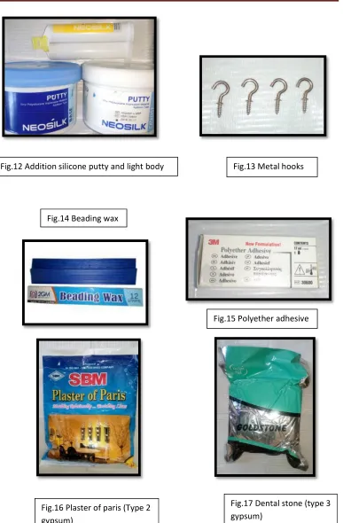
15. Beading wax (Giriraj dental products, Mumbai, India) (Fig. 14)
16. Cold mould seal (DPI, Dental products of India, Wallace street, Mumbai,
India)
17. Sand paper
ARMAMENTARIUM
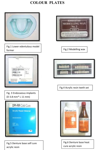
1. Lower edentulous model former (Fig. 1)
2. Surveyor (Ney surveyor, Neytech, Dentsply, USA) (Fig. 28)
3. Flasks and clamps
4. Laboratory lathe (Fig.25)
5. Carbide burs (Fig. 26)
6. Locator abutment driver and Wrench (Locator Core Tool & Locator Torque
Wrench, Zest Anchors LLC) (Fig. 20 & 23)
7. Acrylic trimmers (Fig. 26)
8. Straight fissure bur (Meisinger straight fissure carbide FG bur, HM31-010,
Germany) (Fig. 26)
9. Sand paper mandrel (Fig. 26)
10. Cotton rag wheel
11. Internal hex driver (Myriad plus, Equinox, Amersfoort, Netherlands) (Fig. 23)
12. Spirit lamp (Fig. 27)
13. Chip blower (Fig. 27)
14. Wax knife (Fig. 24)
16. Metal scale (Fig. 27)
17. B.P blade no. 15 with handle (Fig. 24)
18. Rubber bowl (Fig. 24)
19. Stainless steel spatula (Fig. 24)
20. Divider (Fig. 24)
21. Hot plate spatula (Fig. 24)
22. Wax spatula (Fig. 24)
23. Acrylic mixing jar
24. Dental flasks and clamps
25. Prefabricated metal hooks (Fig. 13)
26. Stainless steel metal chains (Fig. 19)
27. Metal plate with nails and bolts (Fig. 18)
28. Universal testing machine (Kalpak industries, Pune, Maharashtra, India) (Fig.
29)
29. Curing water bath (Delta, Gurgaon, Haryana, India) (Fig. 22)
1. Fabrication of test specimens
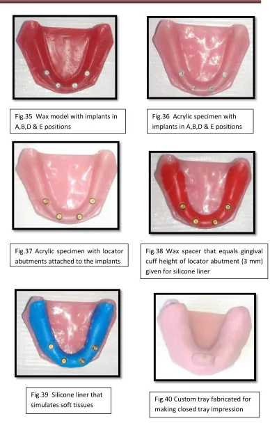
A. Preparation of mandibular edentulous wax model
Modelling wax (Hindustan, Chapel road, Hyderabad, India) was cut in to pieces
and melted in a hot water bath (Delta, Gurgaon, Haryana, India) using a stainless
steel vessel. Then, the melted wax was allowed to flow into the mould space of a
mandibular edentulous model former till the wax completely filled the mould.
The wax was allowed to cool and harden. The model former with the wax was
left for 2 hrs at room temperature, to ensure complete solidification of the wax.
Later, the wax model was retrieved from the model former (Fig.30). For the
purpose of giving soft tissue replica with silicone in the acrylic test model,
grooves of 3 mm (equivalent to the locator abutment cuff height) depth were
made in the wax model using a wax spatula. Depth of 3 mm was ensured by
having a marking in the wax spatula (Fig.31). Then, till the depth of the grooves,
the wax model was completely scraped with a wax carver (Fig.32).
B. Incorporation of implants into the wax model
Four implants (Myriad plus, Equinox, Amersfoort, Netherlands) of diameter 3.8
mm and length 11 mm were placed in the wax model after ensuring parallelism
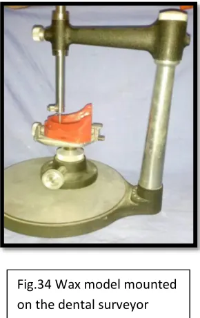
with the help of a surveyor (Ney surveyor, Neytech, Dentsply, USA) by the
following method. The wax model was locked in the surveying table in such a
way that it was parallel to the surveying platform. Two markings were made with
a permanent marker for the implants to be placed in B and D positions with an
made for the implants to be placed in A and E positions with an inter implant
distance of about 35 mm between them29 (Fig.33).
Impression coping was attached to the implant with the help of an internal
hex driver (Myriad plus, Equinox, Amersfoort, Netherlands) and the complex
was attached to the surveying arm of the surveyor. Then, the surveying arm was
lowered on to the wax model and made to contact the ridge area corresponding to
the markings made (Fig.34). The wax in that area was softened with a heated wax
knife and the surveying arm was further lowered in to the wax model, thereby
submerging the implants in to the wax model. It was ensured that the surface of
the implant was at the level of the crest of the ridge. Once the wax hardened, the
impression coping & the implant complex which was attached to the surveyor
arm was then detached from the surveyor. Similarly, all the other 3 implants were
placed and thus, a wax model with four implants in A,B,D & E positions was
obtained (Fig.35). The impression copings were kept attached to the implants till
the wax model was processed in acrylic. These impression copings helped in
maintaining the position of the implants during the processing of the test
specimen.
C. Processing of the test specimen with implants
The wax model was processed in heat cure pink acrylic resin using conventional
flasking & lost wax technique.15 Once the wax model was processed in acrylic,
the impression copings were removed. The acrylic model was then trimmed with
acrylic and carbide burs & then smoothened with sand paper. Polishing was done
on a dental lathe with cotton rag wheel and pumice. Thus, acrylic test model with
D. Simulation of soft tissue with silicone liner
1.To simulate the soft tissue, a silicone liner was given on the ridge surface for
about 3 mm thickness matching the gingival cuff height of the locator
abutments.7 This was done by first placing the locator abutments (Zest Anchors)
into the implants in the acrylic model using abutment driver (Locator Core Tool,
Zest Anchors LLC) and then, tightened to 30 Ncm with a wrench (Locator
Torque Wrench, Zest Anchors LLC) f
instructions37(Fig.37). Two thickness base plate wax (Hindustan, Chapel road,
Hyderabad, India) of about 3 mm thickness was then adapted on the ridge surface
of the acrylic model surrounding the abutments (Fig.38). Flasking was done in a
conventional method. After the setting of the plaster, the flask was opened & the
test model was removed from the mould cavity. Then, the wax layers were
removed from the model. Addition silicone light body (Neosilk, Calmed Invest
kft., Busan, Korea) was mixed and placed in that mould cavity. Then, counter
part of the flask along with the model was placed over that. Then the flask was
tightened with the clamp. After setting of the addition silicone, the model was
retrieved from the flask. Thus, the test specimen with a resilient silicone soft liner
was fabricated (Fig.39).
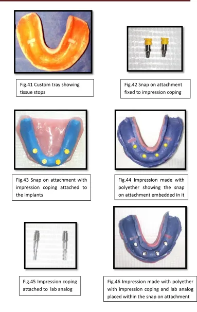
E. Fabrication of custom trays and impression making
Custom tray was fabricated for making closed tray impression. The locator
abutments were then removed and the impression copings along with snap on
attachments (Myriad plus, Equinox, Amersfoort, Netherlands) (Fig. 42) were
attached to the implants in the acrylic model using an internal hex drive (Myriad
plus, Equinox, Amersfoort, Netherlands) (Fig.43). Two sheets of wax were
snap on and rest of the ridge. Two tissue stoppers were given in the molar region
on both the sides. Special tray for closed tray impression technique was
fabricated with auto-polymerising resin (DPI pink, Dental products of India,
Wallace street, Mumbai, India) using dough method and a handle was placed in
the anterior region (Fig.40 & 41). Wax spacer was removed from the custom tray
and tray adhesive (Polyether adhesive, 3 M, Deutschland GmbH, 41453 Neuss,
Germany) was applied to the tray. Polyether medium body impression material
(ImpregumTM soft, 3M ESPE, Deutschland, Neuss-Germany)57,58 was mixed.
Then, the custom tray was loaded with the impression material and the
impression was made by correctly seating the tray in position. After ensuring that
the material had set, the tray was removed from the model and thus, the snap on
attachments were embedded in the impression in their respective positions
(Fig.44).
F. Fabrication of stone casts
The impression copings were then removed from the test specimen and attached
to the implant analogs (Myriad plus, Equinox, Amersfoort, Netherlands) (Fig.45).
The complexes were positioned correctly within the snap on attachments
(Fig.46). The impression was beaded using beading wax (Giriraj dental products,
Mumbai, India). To get soft tissue mollage, condensation silicone light body was
mixed and injected around the impression copings in the impression. Then, stone
cast was poured with type 3 gypsum (Gold stone, Asian chemicals, Rajkot,
India). On retrieval of the stone cast from the impression, the implant analogs got
incorporated into the stone cast. The impression copings were then removed and
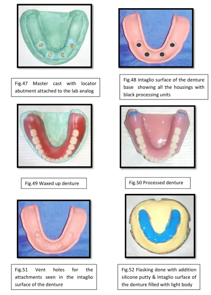
G. Attaching locator attachment sets on the stone model
The locator abutments were then screwed into the implant analogs in the stone
model using abutment driver (Locator Core Tool, Zest Anchors LLC) and then,
tightened to 30 Ncm with a wrench (Locator Torque Wrench, Zest Anchors LLC)
(Fig.47). Complex of attachment metal housings & black processing units were
attached to the locator abutments.
H. Fabrication of record base and occlusion rim
Permanent record base was constructed on the stone cast by adapting a modelling
wax sheet, flasking, dewaxing and packing with heat cure acrylic resin (DPI
pink, Dental products of India, Wallace street, Mumbai, India). Curing was
carried out . Metal housings with
black processing units were embedded in the intaglio surface of the denture base
(Fig.48). Occlusion rim was constructed with modelling wax to an anterior height
of 18 mm and a posterior height corresponding to the 2/3rd of the retromolar pad.
It had a width of about 5 mm anteriorly and 8 mm posteriorly.
I. Fabrication of trial denture
Teeth arrangement was done following the principles of teeth setting for the
lower teeth using acrylic teeth set (Medilux, Meadway dentals Pvt. Ltd., New
Delhi, India). Wax up and polishing was done (Fig.49).
J. Processing of the denture
The waxed up denture was then flasked and dewaxing was done. The permanent
denture base with the housings was retained in its position in the flask, after the
India, Wallace street, Mumbai, India) was packed and curing was carried out.
Thus, processed denture with metal housings in A,B,D & E positions was
obtained. It was then trimmed and polished (Fig.50).
K. Removal of attachment housings from the processed denture
The metal housings were then removed from the denture using straight fissure
bur (Meisinger straight fissure carbide FG bur, HM31-010, Germany) before
duplication and vent holes were formed in all the four A,B,D & E positions
(Fig.51). Such vent spaces were created for attaching the attachment housings in
the test dentures after duplication. The advantage of creating exact space for
housing was that it would prevent change of angulation of housings in the test
dentures during the attachment of metal housings procedure.
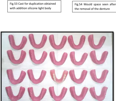
L. Duplication of test dentures
A regular dental flask was used for the fabrication of duplicate dentures. Addition
silicone putty (Neosilk, Calmed Invest kft., Busan, Korea) was mixed and placed
inside the body portion of the flask and the occlusal surface of the denture was
invested into the putty. The putty was adapted along the entire border of the
denture including the lingual side. Petroleum jelly was applied as a separating
medium over the putty to prevent adhesion of the second layer of putty. Addition
silicone light body (Neosilk, Calmed Invest kft., Busan, Korea) was mixed and
placed in the intaglio surface of the denture and again addition silicone putty was
mixed and kept over it and in the base of the flask. The flask was closed after
ensuring the proper seating of the base. After the setting of addition silicone, the
test denture was removed from the flask leaving a mould space (Fig.52,53 & 54).
Auto-polymerising resin (DPI pink, Dental products of India, Wallace
in to the mould space. Then, the flask was closed properly and allowed for curing
of the resin. After the completion of curing of the resin, deflasking was done &
the duplicated denture was retrieved from the mould and kept in pressure pot
maintained at a pressure of 20 psi for 20 min52. Then the duplicated denture was
trimmed and polished. Similarly, twenty duplicated dentures were fabricated for
both the groups (Fig.55). As there was tearing of the addition silicone material
after removal of about 3 duplicated test dentures, the material was changed ie.,
the flasking procedure was repeated after duplication of 3 duplicated test
dentures.
M. Incorporation of locator attachments in all test dentures
After the completion of the processing work, the locator abutments were removed
from the analogs in the stone model and were screwed into the acrylic test
specimen using the abutment driver (Locator Core Tool, Zest Anchors LLC) and
then, tightened to 30 Ncm with a wrench (Locator Torque Wrench, Zest Anchors
LLC). For the first group (group A), metal housings with black processing units
were placed in B and D positions of the locator abutments in the test specimen
(Fig.56) and the test denture was checked for adaptation by placing it on the test
specimen to ensure complete seating of the denture. Then, auto-polymerising
resin was added to the location of vent holes (B & D positions) in the test denture
and placed over the housings in the test specimen. Thus, the attachment housings
were picked up in B & D positions and the remaining vent holes in A and E
positions in the test denture were closed using auto-polymerising resin (Fig.57).
In the same way, ten dentures were made for group A specimens (Fig.58).
Similar procedure was done in a vice-versa manner for the attachment of
The black attachments were then replaced by transparent Locator
attachments (Locator medium retentive caps) using a Locator Core Tool (Zest
Anchors LLC). Transparent Locator attachments were tested in this experiment,
as they were considered the most retentive nylon caps10 (Fig.62 & 63).
2. Evaluation of retention and stability using Universal testing
machine
A. Attachment of hooks in the test dentures
The retention and stability was tested by subjecting the dentures to tensile forces
in different directions. The tensile force was applied to the dentures by attaching
chains to hooks attached to dentures on one side and the tensile load cell of the
Universal testing machine (Kalpak industries, Pune, Maharashtra, India) on the
other side. Four preformed metal hooks with a radius of 3 mm were attached to
each of the test dentures. Two hooks were attached in the cingulum portion of
canine teeth on either side and other two hooks were attached in the occlusal
surface (central fossa) of second molar on either side. The hooks were attached in
the denture using auto-polymerising resin. The hooks were attached in such a
way that the top surface of the hooks were all at the same level. This was verified
by placing a glass plate with spirit columns over the hooks (Fig.64). Thus, 4
hooks were attached to all the test specimens (Fig.65).