Caitlin Mueller, Sigrid Adriaenssens (eds.)
Copyright © 2018 by Paolo Beccarelli & Roberto Maffei
Pneumatic membranes for biogas plants
Paolo BECCARELLI*, Roberto MAFFEIa
*Affiliation of Corresponding Author Address of Corresponding Author Email Address of Corresponding Author
a Maco Technology srl
Abstract
The biogas sector had a rapid development in the last decade with several new industrial plants realized all over Europe and Worldwide. The intrinsic efficiency of membrane structures [1] provided a cost effective solution to cover digesters, bio-filters, lagoons and gas holders through different concepts such as floating membranes, anticlastic geometries and pneumatic structures. However, after less than ten years of use, the structures show several critical aspects, generally related to the premature corrosion of the membrane, the failure of the joints and the overload due to strong winds and heavy snowfalls. This paper presents a review of the main structural solutions based on a pneumatic concept such as air-halls, pneumatic beams and floating roofs. The description will be supported by case studies of each type of structure including air-halls for digesters and bio-filters, Tensairity® and pneumatic beams for long span roofs, floating roofs for large lagoons. For each case study the authors will present data and examples related to the design, manufacturing and installation of the membrane and the issues related to the rapid degradation of the performance of the structure due to the extreme corrosive environment based on high temperatures and high concentration of corrosive chemicals. Finally, the paper will offer a review of the current precautions and solutions to reduces the risks of failures and to improve the expected lifespan of the structures.
Keywords: membrane structures, biogas, Tensairity, coated fabrics, architectural membranes, air-halls, floating roofs, pneumatic beams.
1. Introduction
Biogas is a renewable energy source characterized by a reduced carbon footprint. For this reason the production of biogas is considered a strategic market for the achievement of the environmental targets agreed by the governments of the major European economies. In the last decade the incentives provided by the local European governments boosted the development of a new generation of industrial plants in which coated fabrics became the only cost effective way to cover large digesters, bio-filters, lagoons and gas holders. The size of the membrane roofs varies from 500 m2 to 1200m2 and it is estimated that there are around 2000 structures in Italy with similar figures for the other major European economies.
2. Pneumatic membrane roofs for digesters, bio-filters, lagoons and gas holders
storage tanks/lagoons (5) and then retrieved for further uses such as high quality fertilizers and dry fertilizers. The biogas released during the fermentation is accumulated in the roof of the fermenter (8) and then processed (and supplied to the national grid or gas filling stations) or burned in a combined heat and power plant (CHP) (9) to generate electricity and heat which are fed directly into the power grid (10) and used for industrial applications (11).
Figure 1: Diagram of operation of a biogas plant (source: WELTEC BIOPOWER GmbH)
2.1. Digesters
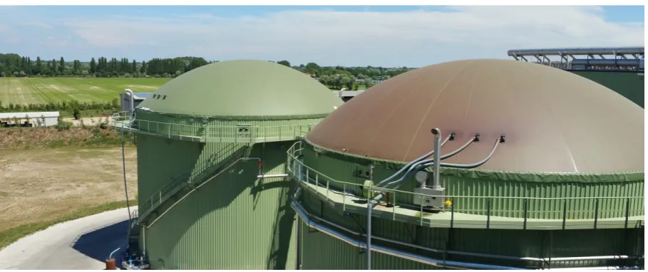
The digesters are generally based on a circular geometry realized in concrete or steel and covered with a double layer membrane roof supported by the internal pressure (pneumatic domes) or by a central pole (cones). The internal layer prevents the release of gas in the atmosphere and requires an exceptional resistance to the high concentrations of corrosive chemicals, the external layer protects the roof from the weather and the accidental loads (snow, wind, rain etc.). The solution is very effective and it is widely used in the current biogas plants.
Figure 2: Typical double layer pneumatic roof for digesters. The change in the colour of the membrane roof it is clearly visible and it is related to the degradation of the membrane due to the aggressive chemical environment.
(source: Maco Technology srl).
2.2. Bio-filters
[image:2.595.72.527.430.621.2]concentration of aggressive chemicals, these type of structures are probably the less problematic of the structures presented in this paper.
2.3. Lagoons and storage tanks
[image:3.595.73.526.281.464.2]Lagoons and storage tanks are large structures designed to store the sewage after it has been treated, they could be circular, elliptical or rectangular. Unlike the digesters they are generally covered by a single layer with lower performances due to the reduced temperatures and concentrations of corrosive chemicals. The membrane roof protects the tank form the rain water and prevent the release of gas (which in some cases is aspirated and used to produce energy) usually quite intense to the olfactory senses. The gas released by the sewage can contribute up to 10-15% of the total production of gas, for this reason in recent years large industrial plants started to demand membrane roofs able to maintain a cavity between the liquid and the membrane where the gas can be accumulated and extracted. The structures represented in figure 3 and figure 4 are pilot projects designed to address this requirement and offer a effective solution to the problems related to the drainage of the rain water.
Figure 3: Rectangular lagoon covered with a pneumatic beam [5] derived from the Tensairity® concept with a total span of 45m (source: Maco Technology srl).
Figure 4: Circular lagoon covered with a pneumatic floating roof with a diameter of 65m (source: Maco Technology srl).
2.4. Gas holders
[image:3.595.72.526.507.690.2]the gas produced. The structures of a membrane tank is generally based on a double membrane system with an external membrane for weather protection, an internal airtight membrane to store the gas and a bottom membrane designed to enclose the gas space. At this stage, the gas is generally less corrosive than the mix of chemical produced in the digesters, however, for safety reason it is crucial that the gasholder is completely airtight and in good conditions during the entire service life. I small damage could cause the loss of gas with consequences in terms of safety and economic losses.
Figure 5: Example of a double-membrane gasholders [6] (source: GTI Covers)
3. Technical challenges and common failure modes
Coated fabrics are the only materials that provide a cost effect solution for the covering of the large structures for the biogas sector such as digester or lagoons. Metallic roofs require an expensive protection to prevent the corrosion and the use of stainless steel makes the structure unaffordable form the client’s perspective.
PVC coated fabrics are widely used in the building sectors especially for temporary/seasonal buildings and large projects which require a cost effective solution due to the thousands of square meters to be covered. However, the use of architectural fabrics for industrial applications could lead to the structural failure of the structure due to the extreme environmental conditions characterized by high temperature and high concentrations of corrosive chemicals combined with the accidental loads such as snow and windloads.
For this reason several producers developed specific products with additional protective coatings able to withstand the extreme environmental conditions and achieve the expected lifespan which, for biogas plants, is between 5 and 10 years. A typical PVC coated polyester fabric for biogas applications has a permeability to the methane gas from 30 to 400 cm3/m2.d.bar [3] and the antistatic treatment <1x10⁹ Ω/m2
according to the standard which specifies the basic method and requirements for the design, construction, testing and marking of non-electrical equipment intended for use in potentially explosive atmospheres in air of gas, vapour, mist and dusts [4]. In addition, some material producers specifies the chemical compatibility of their products.
Despite the development of a new generation of coated fabrics, the tensioned membrane structures for biogas plants are still quite problematic in terms of durability of the membrane, mechanical stability of the connections and overall structural behaviour of the structures.
3.1. Corrosion of the membrane
corrosive chemicals penetrated the fabric form the edge along the fibres and destroyed the protective coating from the inside.
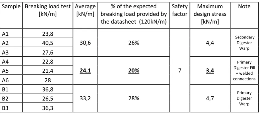
[image:5.595.73.525.170.296.2]The degradation of the fabric due to corrosion is confirmed by mechanical tests on a similar case study of a 5 years old digester where the breaking load of the fabric decreased by 72-80% from to the expected breaking load provided by the datasheet
Figure 6: Degradation of a PVC coated polyester fabric due to the exposure to the chemicals of a biogas plant (source: Maco Technology srl).
Table 1: Mechanical tests on samples of a 5 years old digester (source: Maco Technology srl).
Sample Breaking load test [kN/m]
Average [kN/m]
% of the expected breaking load provided by the datasheet (120kN/m)
Safety factor
Maximum design stress
[kN/m]
Note
A1 23,8
30,6 26%
7
4,4 Secondary Digester
Warp
A2 40,5
A3 27,6
A4 22,8
24,1 20% 3,4
Primary Digester Fill
+ welded connections
A5 21,4
A6 28
B1 36,8
33,2 28% 4,7 Digester Primary
Warp
B2 26,5
B3 36,3
3.2. Failure of the joints
[image:5.595.70.527.360.560.2]Figure 7: Damages to the welded seams due to the high temperature that during a sunny day in the warm season reaches 66.5°C (source: Maco Technology srl).
3.3. Strong winds
Membranes structures are appreciated in biogas applications thanks to their light weight and high strength combined with the flexibility and elasticity of coated fabrics. However, the light weight of fabric structures makes them prone to wind load and may result in fluttering. In extreme circumstances, this fluttering may induce unexpectedly high tension forces in the fabric and in correspondence of the connection points. Figure 8 show a typical damage caused by the movement of the membrane in correspondence of the rigid boundaries. The effect of the wind, combined with the effect of the early degradation of the fabric, results in damages which are generally unusual for architectural membrane structures with the same age.
Figure 8: Damage in correspondence of a rigid boundary due to the strong wind and the progressive decrease of the mechanical performance of the coated fabric (source: Maco Technology srl).
3.4. Heavy snowfalls
[image:6.595.175.424.390.576.2]Figure 9: Failure due to snow load (source: Maco Technology srl).
4. Conclusions and technical recommendations
An XRF analysis and a FT-IR analysis on the sample described in 3.1 highlighted that the failure of several membrane structures used in corrosive environments like biogas plants are related to the inadequacy of several coated fabrics for heavy duty applications in presence of corrosive gases such as H2S and ammonia. Engineers and manufacturers should take into account, with adequate material specifications and safety factors, of the rapid decrease of the mechanical performance of coated fabrics exposed to corrosive environments. The tensile strength can decrease at a rate of 15% per year reaching a critical value in less than 5 years. If combined to external loads, such as snow or wind, this can led to the premature failure of the membrane roof. The EU funded research project MULTITEXCO [7] supported the development of two sensors designed to show an irreversible colour change which allow the detection of the misuse of a coated fabric which is not suited for biogas fermentation and the consequent contact with corrosive gases. This is a common situation in case the manufacturer uses coated fabrics designed for other applications or when the client uses the biogas plant with a different substrate which releases concentration of gasses different from what considered for the initial design.
Acknowledgements
This paper includes results obtained during the research project MULTITEXCO funded by the European Union's Seventh Framework Program under grant agreement n° 606411.
References
[1] P. Beccarelli, Biaxial Testing for Fabrics and Foils: Optimizing Devices and Procedure, Springer, 2015.
[2] http://www.weltec-biopower.com.
[3] DIN 53380-2 “Testing of plastics - Determination of gas transmission rate - Part 2: Manometric method for testing of plastic films”
[4] EN 13463-1:2001 “Non-electrical equipment for potentially explosive atmospheres. Basic method and requirements”
[5] P. Beccarelli and R. Maffei, 2017. Structural roofing system and method of using the same, EP2868844A1
[6] http://www.gticovers.com
![Figure 3: Rectangular lagoon covered with a pneumatic beam [5] derived from the Tensairity® concept with a total span of 45m (source: Maco Technology srl)](https://thumb-us.123doks.com/thumbv2/123dok_us/8553185.363443/3.595.72.526.507.690/figure-rectangular-covered-pneumatic-derived-tensairity-concept-technology.webp)
![Figure 5: Example of a double-membrane gasholders [6] (source: GTI Covers)](https://thumb-us.123doks.com/thumbv2/123dok_us/8553185.363443/4.595.175.423.176.310/figure-example-double-membrane-gasholders-source-gti-covers.webp)