DESIGN OF ANTENNA WITH NOTCH FILTER TO SUPPORT MULTIFUNCTION OPERATION STANDARDS IN WIRELESS
COMMUNICATION SYSTEMS
HAFEDH ABDULLAH MOFREH DHAFER AL-KHAWLANI
This report is submitted in partial fulfilment of the requirement for the award of Bachelor of Electronic Engineering (Telecommunication Electronic) With Honours
Faculty of Electronic and Computer Engineering UNIVERSITI TEKNIKAL MALAYSIA MELAKA
DECLARATION
I hereby declare that this report entitled “Design of Antenna with Notch Filter to Support Multifunction Operation Standards in Wireless Communication Systems” is the result of my own work and that, to the best of my knowledge and believe. It contains no material previously published or written by another person except for quotes as cited in the references and also no material which to a substantial has been submitted for the award of any other degree or diploma of a university or other institution of higher learning.
Signature: ...
Name : Hafedh Abdullah Mofreh Dhafer Al-Khawlani
ii
APPROVEL
“I hereby declare that I have read through this report entitled “Design of Antenna with Notch Filter to Support Multifunction Operation Standards in Wireless Communication Systems” and found that it is sufficient to a comply the partial fulfilment for awarding the degree of Bachelor of Electronics Engineering (Telecommunication Engineering) with Honours”
Signature : ……… Signature: ………
Supervisor:Dr. Yosza Bin Dasril Co-supervisor: PM. Dr. Zahriladha bin Zakariar.
iii
DEDICATION
iv
ACKNOWLEDGEMENT
First and foremost, I would like to praise to Allah S.W.T for giving me a little strength and ability to do my final year project and eventually succeed to complete my report as required. I would like to express my gratitude to my supportive supervisor, Dr. YOSZA BIN DASRIL and Dr. ZAHRILADHA BIN ZAKARIA for providing his insightful knowledge and valuable assistance throughout this project under his guidance.
I would like to take the chance to thank all lecturers who taught me in the past four years and had a great contribution that qualify me to do my final year project. I would like to thank Dr. Kok Swee Leong, and lecturers who arrange for INOTEK exhibition, for their efforts in providing information and cooperation to help students achieving the goals of final year projects. I would like to thank the technicians, Mr.Imran bin Mohamed Ali and Mr Mohd Sufian bin Abu Talib for their cooperation during fabrication and measurement processes.
A particular line of appreciation is extended to my parents, for their unflagging encouragement and support throughout my studies. Their suggestions and ideas were very useful as it helped me to successfully complete my final year project and studies. I would like to thank all senior students who helped and encouraged me though out my studies.
Thanks as well to all my acquaintances for their counsel and knowledge they provide to me. Lastly, my thanks as well extend to whoever supported me directly or indirectly in doing my final year project and throughout my studies.
v
ABSTRACT
vi
ABSTRAK
Dalam projek ini adalah saiz yang UWB patch antena kecil dengan penapis takuk tunggal.
Slot U berbentuk dimuatkan dalam patch antena untuk WiMAX jalur frekuensi penolakan.
antena simulasi menggunakan perisian CST Microwave Studio. Dimensi slot secara
sistematik dikira dan dioptimumkan untuk mencapai balas band penolakan yang
dikehendaki. Penapis takuk tunggal boleh dilaksanakan menggunakan slot U berbentuk
tertanam pada patch untuk WiMAX jalur frekuensi penolakan. Dalam usaha untuk
mencapai ciri-ciri untuk antena patch. Keputusan yang dicapai telah menunjukkan
bahawa antena boleh berfungsi dalam julat keseluruhan kekerapan UWB kerja (3.1 GHz
kepada 10.6 GHz). Sebaliknya, ia menolak Dia WiMAX (3,13-3,7 GHz) jalur frekuensi.
antena simulasi menggunakan perisian simulasi Suite CST Studio. Perbandingan prestasi
antena adalah untuk mengambil tempat, dari segi parameter antena seperti keuntungan,
kehilangan pulangan, jalur lebar dan corak radiasi. Manakala keputusan yang diperolehi
vii
TABLE OF CONTENTS
DECLARATION i
APPROVEL ii
DEDICATION iii
ACKNOWLEDGEMENT iv
ABSTRACT v
ABSTRAK vi
TABLE OF CONTENTS vii
LIST OF TABLES xi
LIST OF FIGURES xii
CHAPTER I 1
INTRODUCTION 1
1.1 Introduction 1
1.2 Problem Statement 1
1.3 Objectives 2
1.4 Scope of Work 2
1.5 Methodology 2
1.6 Contribution of Project 5
CHAPTER II 6
LITERATURE REVIEW 6
3.1 Introduction 6
3.2 Need for (UWB) filters and challenges 6
3.3 Critical Literature Review 7
viii
3.5 Antenna theory 10
2.5.1 UWB Features 11
2.5.2 Interference Reduction 11
2.5.3 Advantages of UWB 12
2.5.4 Comparison with other technologies 12
2.5.5 Notch filter 13
3.6 Antenna Properties 13
2.6.1 Impedance 14
2.6.2 Return Loss 14
2.6.3 VSWR (Voltage Standing Wave Ratio) 14
2.6.4 Bandwidth 15
2.6.5 Radiation Pattern 15
2.6.6 Gain 15
3.7 Micro-strip Antenna 16
2.7.1 Metallic Patch 16
2.7.2 Dielectric Substrate 17
2.7.3 The Ground 17
2.7.4 Feeding 17
2.7.4.1 Coaxial feeding 17
2.7.4.2 Micro-strip Feeding 18 2.7.4.3 Proximity Coupled Feeding 19 2.7.4.4 Aperture–Coupled Feeding 20 3.8 Advantages and Disadvantages of Microstrip Antenna 21
3.9 Conclusion 22
CHAPTER III 23
METHODOLOGY 23
ix
3.2 Design Techniques and Software 25
3.2.1 CST Microwave Studio 25
3.2.2 Antenna Specifications and Design 27
3.2.3 Circular Patch Antenna 28
3.2.4 Transmission line Microstrip Patch Antenna 29 3.2.5 Feeding of Patch Antenna 30 3.3 Design Parameter of Circular Antenna 31
3.4 Fabrication Process 31
3.5 Conclusion 32
CHAPTER IV 33
RESULTS AND DISCUSSION 33
4.1 Introduction 33
4.2 Antenna Result 33
4.2.1 Antenna Simulation Design Results 33
4.2.2 Primitive Antenna 34
4.2.3 Antenna with U-slot (for band-notch at 3.15 - 3.7 GHz) 35
4.2.4 Gain 36
4.2.5 Radiation Pattern 37
4.2.6 Impedance Matching 38
4.2.7 The Directivity 39
4.3 Measurement Result of the Antenna 39
4.3.1 Return Loss 39
4.3.2 Gain 41
4.3.3 Radiation Patterns 43
4.4 Conclusion 45
CHAPTER V 47
x
5.1 Introduction 47
5.2 Conclusion 47
5.3 Future Work 48
REFERENCES 50
xi
LIST OF TABLES
TABLE TITLE PAGE 2.1 Summary of the sample journals literature review 7-10
3.1 The design characteristic of the antenna 27
3.2 Design Specifications of Patch Antenna 28
xii
LIST OF FIGURES
Figures TITLE PAGE
1.1 a-Cst Software, b-PCB Hardware 3
1.2 Flowchart of project 4
2.1 R-C notch filter 13
2.2 Basic Microstrip antenna 16
2.3 Different shapes for microstrip antenna 16
2.4 Coaxial feeding 17
2.5 Direct microstrip feed line 18
2.6 Inset microstrip feed line 19
2.7 Gap-coupled microstrip feed line. 19
2.8 Proximity coupled microstrip feeding 20
2.9 Aperture coupled microstrip feed 21
3.1 The flow chart of the project 24
3.2 CST Studio Suite and CST Microwave Studio 26
3.3 The workspace of the software 26
3.4 The side view of the antenna 27
3.5 The optimize parameters. 31
3.6 Fabricated UWB circular patch antenna 32
4.1 Geometry of UWB monopole antenna 34
4.2 Return loss & Bandwidth for UWB antenna 35 4.3 Geometry of UWB antenna with U-slot to produce band-notch 35 4.4 Return loss & Bandwidth for UWB antenna with notch filter
U-shaped
36
4.5 Results simulation gain 37
4.6 Simulation of Radiation Pattern 37-38
4.7 Impedance matching 38
4.8 The directivity of UWB antenna 39
xiii
4.10 Measurement and simulation return loss & bandwidth for the UWB antenna
40
4.11 The comparison results gain for simulations and measurements 41
4.12 Anechoic Chamber View 43
4.13 The compression simulations and measurements for Radiation pattern
CHAPTER I
INTRODUCTION
1.1 Introduction
The purpose of this project is to design a device that have small antenna with single notch band at 3.1–10.6GHz ultra-wideband (UWB) for wireless communication applications. It uses to support multifunction operation standards in wireless communication systems by using micro-strip patch and a perfectly conducting ground plane. Currently, various antennas have been designed for wireless communications applications. However, these antennas either they are expensive to build due to fabrication difficulty or having large size. Therefore, in this project an UWB is going to be designed at operating frequency of 3.1 to 10.6 GHz with introducing a wide slot to achieve a notch band filter at WiMAX (3.15-3.7) GHz. This is due to various advantages of UWB antennas such as cost effective, compact in size and having high gain. The range of this project is limited to certain application for wireless communications such as WLAN (5.15-5.85 GHz). The proposed UWB antenna will be designed and simulated by using the commercially available CST Microwave Studio Software. Then, the simulation results will be validated and verified through experimental results. It is believed that the proposed UWB antenna is going to be developed for WLAN, Smart Sensor Network, and other Wireless Communications applications.
1.2 Problem Statement
2
be used for many applications in the same time. [19] This is due to its advantages such as ease of fabricating, cost effective, has efficient radiators and it can support both linear and circular polarization.
1.3 Objectives
a. To design Ultra-wideband (UWB) antenna with single notch filter to support multifunction operating standards frequencies for wireless communication system applications.
b. To simulate and fabricate a micro-strip patch antenna using CST software. c. To validate and verify the simulation results with measurement results.
1.4 Scope of Work
This project will mainly focus on the design and analysis, testing and measurement of Micro-strip patch antenna captures by the communication system in the frequency range of UWB (3.1-10.6 GHz) except for WiMAX at (3.15-3.7GHz). Furthermore, a single notch will only be used as filter for undesired frequencies or rejected frequencies. This project limits to certain applications on wireless communications systems such WLAN. CST (computer simulation technology) software will be utilized to design the antenna. After completing the design process, the next procedure is to fabricate circuits and do testing and measurement. This includes a comparison between the simulation result and the measurement results. The purpose of this project is to validate and verify the simulation results of a micro-strip patch antenna for UWB usage.
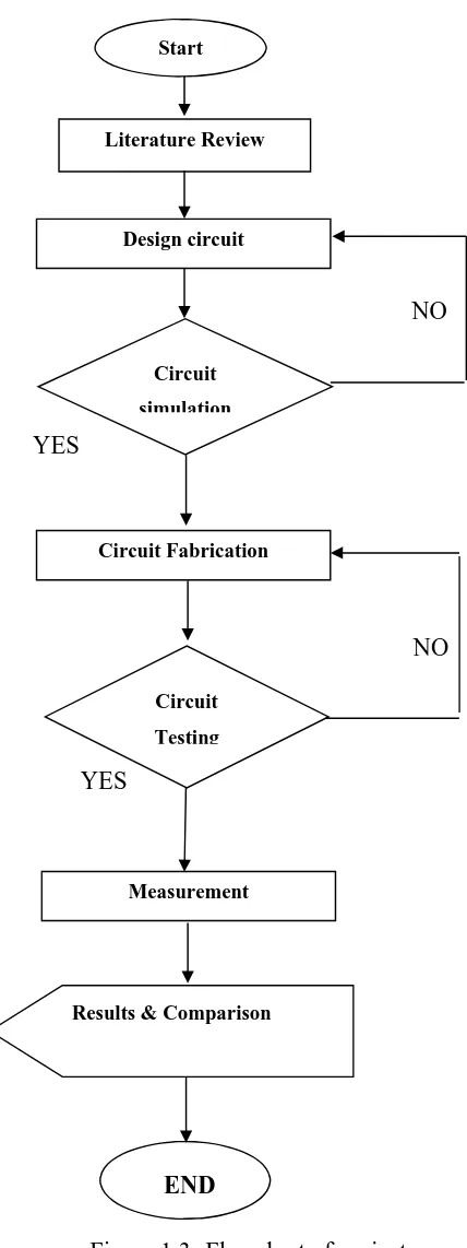
1.5 Methodology
3
observe the result of return loss, bandwidth, gain and directivity of the antenna design. When all the specifications meet the requirement, the fabrication process of the antenna will be carried out. Next to the testing and measurement of the fabricated antenna will be carried out hence again will compare it with all the calculated and simulated results. All experimental results will be included in the final report. Figure 1.3 shows the flowchart of the project development
Software and hardware:
The software program that will be used for designing the proposed UWB antenna is CST. Computer Simulation Technology (CST) Microwave Studio offers accurate, efficient computational solutions for electromagnetic design and analysis. 3D EM simulation software is user-friendly and enables you to choose the most appropriate method for the design and optimization of devices operating in a wide range of frequencies. CST STUDIO is a specialist tool for signal integrity (SI), power integrity (PI), and electromagnetic compatibility (EMC) analysis on printed circuit boards (PCB). It integrates easily into the EDA design flow by providing powerful import filters for popular layout tools.
(a) (b)
Figure 1.2 a-CST Software b-PCB Hardware
4
NO
YES
NO
YES
[image:18.612.199.413.85.656.2]END Figure 1.3: Flowchart of project
Start
Literature Review
Design circuit
Circuit
simulation
Circuit Fabrication
Circuit
Testing
Measurement
5
1.6 Contribution of Project
A few years when the first investigation on ultra-wideband (UWB) wireless system, considerable project efforts are place into the design of UWB antenna and systems for communications. This UWB antenna is essential for providing wireless broadband communications supported the utilization of terribly narrow pulses on the order of nanoseconds, covering a really wide bandwidth within the frequency domain, and over terribly short distances at very low power densities. During this project, new models of U slotted UWB antenna proposed by finding out its current distribution characteristics. The wideband behaviour is due to the actual fact that the currents on the perimeters of the slot introduce an extra resonance, which, in conjunction with the resonance of the most patch, turns out an overall broadband frequency response characteristic. This antenna is considerable small than others listed within the references, that its size is a smaller amount than a wavelength, compact, and appropriate for several UWB applications. [15]
6
CHAPTER II
LITERATURE REVIEW
3.1 Introduction
In this chapter, a brief history of UWB antenna technology has been reviewed. The UWB antenna concept has been investigated since many decades. From the literature reviews, the researched journals that were reviewed about designing Ultra-wideband (UWB) antenna at frequency of (3.15-3.7) GHz with notch filter. The UWB technology has knowledgeable about several important developments in recent years. However, there are still challengers in creating this technology live up to its full potential. One specific challenge is that the UWB antenna design. UWB technology has had essential impact on antenna design. The UWB antennas need to be ready to transmit pulses as accurately and efficiently as doable. The spectrum allocated definitely needs transmitters and receivers with band antennas. After correcting the desired journals, Comparisons were carried among them. In addition, this chapter covers a detail theory about an antenna and its parameters that determine its performance.
3.2 Need for (UWB) filters and challenges
The main challenge in UWB antenna design is achieving the extremely wide impedance bandwidth while still maintaining high radiation efficiency. By definition, an UWB antenna must be operable over the entire 3.1 GHz - 10.6 GHz frequency range. As in conventional wireless communication systems, filter plays a vital role in UWB systems also. Filters are required in the UWB systems for the following reasons: [13]
a. Reshaping the UWB signal in order to meet the FCC spectrum regulations. b. Suppressing the interference from the Narrowband (NB) services such as
Worldwide Interoperability for Microwave Access (WiMAX) and WLANs. c. Suppressing harmonics and spurious of oscillators and amplifiers, also to
7
3.3 Critical Literature Review
The literature review examined a comprehensive background of other related research works and the fundamental antenna parameters that should be considered in designing UWB antenna using Micro-strip patch with single notch filter, and potential technologies for physical construction. However, the literature review is performed on journals to collect related information and facts that can be used in the design process of this project prior to design process.
3.4 Results and Analysis
[image:21.612.101.534.333.718.2]Result and analysis of previous literature papers is given in literature review table given in below.
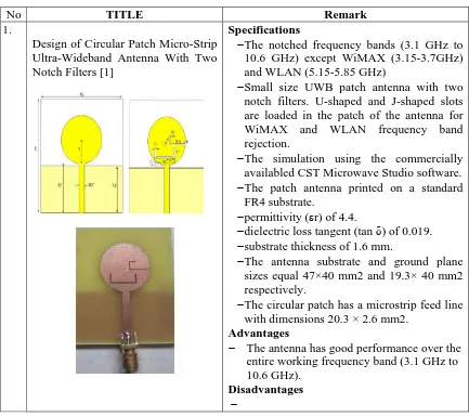
Table 2.1Summary of the sample journals literature review
No TITLE Remark
1.
Design of Circular Patch Micro-Strip Ultra-Wideband Antenna With Two Notch Filters [1]
Specifications
The notched frequency bands (3.1 GHz to 10.6 GHz) except WiMAX (3.15-3.7GHz) and WLAN (5.15-5.85 GHz)
Small size UWB patch antenna with two notch filters. U-shaped and J-shaped slots are loaded in the patch of the antenna for WiMAX and WLAN frequency band rejection.
The simulation using the commercially availabled CST Microwave Studio software. The patch antenna printed on a standard
FR4 substrate.
permittivity (εr) of 4.4.
dielectric loss tangent (tan δ) of 0.019. substrate thickness of 1.6 mm.
The antenna substrate and ground plane sizes equal 47×40 mm2 and 19.3× 40 mm2 respectively.
The circular patch has a microstrip feed line with dimensions 20.3 × 2.6 mm2.
Advantages
The antenna has good performance over the entire working frequency band (3.1 GHz to 10.6 GHz).
8
Results
The gain of the UWB patch antenna decreases to 2 dB at 5 GHz.
the notch filter parameters were optimized to give a good band-reject on the WLAN bandwidth (5.15 to 5.85 GHz) and WiMAX bandwidth (3.2 to 3.7 GHz).
Measured H-plane has gain magnitude of 2.5dB at 266° where was at 7 GHz, also the E-plane has a gain magnitude of 3.5 dB (at Theta = 90°). Finally, a gain of 7.2dB where was shown for E-plane at 9.6 GHz (at Theta= 90°).
2.
Design and Development of UWB notch antenna with fractal geometry [2]
Specifications
The design of coplanar waveguide fed ultra-wide band Antenna with fractal geometry. The designed antenna has a dual band notch
characteristic. circular monopole.
The antenna performance depends on the ground plane width and the feed gap.
Elliptical type of slot, sierpinski fractal dual band elimination monopole UWB antenna. The impedance bandwidth ranges from 1.8
to 11.5 GHz.
FR-4 epoxy substrate having thickness h=1.6 mm, loss tangent (tan δ)=0.02 and dielectric constant εr=4.4.
Advantages
The antenna is good suppression capacity at the 5.2GHz wireless LAN by using elliptical type of slot in the main radiator.
Elliptical type of slot helpful for achieving notched band centered at 5.2 GHz for WLAN rejection.
Results
the resultant bandwidth of 1.8-11.5 GHz with VSWR<2.
Measured H-plane and E-plane.
Resonance dip around 3.1 GHz corresponding to a quarter wavelength of the disc diameter.
Subsequent resonance dips around 5.9 GHz and 7.7 GHz correspond to the higher order harmonics of the fundamental mode.
3. A Band-Notched UWB Monopole Antenna with High Notch-Band-Edge Selectivity [3]
Specifications
second-9
order bandstop filter.
proposed antenna with a second-order maximally flat bandstop filter at 5.5 GHz is presented.
UWB antenna provides good notch-band suppression from 5.15 to 5.95 GHz,
the normalized total radiated powers in the notch band are lower than 12 dB.
high band-edge selectivity andflat return loss in the notch band and it has Stub resonator.
Advantages
Good radiation performance with radiations patch from 3.1 to 10.6 GHz.
Obtain a uniform rejection performance over the whole interference band.
High-quality factor. Disadvantages
The single null of the insertion loss at the center frequency of the bandstopfilter does not benefit the band-edge selectivity.
Results
Band notch from 5.0 to 6.0 GHz.
Measured H-plane has gain 0 dBi at frequencies in the passband and below -10 dBi.
The measured 10-dB return loss bandwidth covered the range from 2.4 to over 11 GHz with a 3-dB notched band from 5.0 to 6.0 GHz
4. Dual Band-Notch UWB Antenna with Single Tri-Arm Resonator [4]
Specifications
Microstrip line-fed planar antenna with dual notched bands of 3.3–3.7 and 5.15–5.825 GHz..
The dual band-notch characteristic is achieved by etching a single tri-arm resonator below the patch.
Bandwidth (return loss 10 dB) ranging from 2.98 to 10.76 GHz with two notched bands operating at 3.5 and 5.5 GHz.
Advantages
Achieved good gain and exhibits
omnidirectional radiation patterns except at notched band.
Disadvantages
10
plane. Results
dual notched bands at 3.5 and 5.5 GHz with an aim to avert the interference
withWiMAX and WLAN in ultrawideband Measured radiation patterns of the proposed
antenna at 3.2, 5.5, and 9.4 GHz in xz-plane and yz -plane.
5. A Novel Reconfigurable Notch-Band UWB Antenna [5]
Specifications
Novel ultra-wideband (UWB) antenna with the reconfigurable notch band.
Elliptical-shaped patch, a 50-Ohm CPW feed line, and a tapered ground plane.
Two-notch-band UWB antenna
(3.3GHz~3.6GHz, 5.15GHz ~ 5.825GHz). The antenna are (unit: mm) L=50,ER=28,
SW=0.5, R=4.3, SD=0.5, F1=17, F2=10, RP=21.5, EL1=16, EL2=10, FW=5.
The FR4 substrate ( r=4.5, h=1.524mm). Advantages
increase the bandwidth of the UWB antenna.
Results
The notch band covers either WiMAX (3.3GHz~ 3.6GHz) band or WLAN for (5.15GHz~5.825 GHz) band.
3.5 Antenna theory
An antenna is an electrical device which converts electric currents into radio wave or radio wave into electric currents. Antenna usually used with a radio transmitter or radio receiver. In transmission, radio transmitter applies an oscillating radio frequency electric current to the antenna’s terminals and the antennas radiate the energy from the current as electromagnetic waves. Antennas that excite an electrical field are referred to as electrical antennas; antennas exciting a magnetic field are called magnetic antennas. The oscillating electrical or magnetic field generates an electromagnetic wave that propagates with the velocity of light, c. In reception, an antenna intercepts some of the power of electromagnetic waves in order to produce tiny voltage at its terminals. An antenna can be used for both transmitting and receiving.