UNIVERSITI TEKNIKAL MALAYSIA MELAKA
OPTIMIZING CERAMIC SHELL THICKNESS TO ENHANCE
ITS PERMEABILITY
This report submitted in accordance with requirement of the Universiti Teknikal Malaysia Melaka (UTeM) for the Bachelor Degree of Manufacturing Engineering
(Manufacturing Design) (Hons.).
by
LEE PEI JING B051210060 920422-14-5288
DECLARATION
I hereby, declared this report entitled “Optimizing Ceramic Shell Thickness to Enhance Its Permeability” is the results of my own research except as cited in the references.
Signature : ………
Author’s Name : ………
APPROVAL
This report is submitted to the Faculty of Manufacturing Engineering of UTeM as a partial fulfillment of the requirements for the degree of Bachelor of Manufacturing Engineering (Manufacturing Design) (Hons.). The member of the supervisory is as follow:
i
ABSTRAK
ii
ABSTRACT
iii
DEDICATION
To my beloved parents To my lovely brothers To my honoured project supervisor
To my humble lecturers To my circle of friends
Thank you Very Much
iv
ACKNOWLEDGEMENT
I would like to express my gratitude and appreciation to all those who gave me the possibility to complete this report which was Final Year Project (FYP). A special thanks to my final year project supervisor, Dr. Shajahan Bin Maidin, whose help, stimulating suggestions and encouragement, helped me to coordinate my project especially in writing this report. His willingness to spend his much precious time and his patience in guiding me was deeply appreciated. Besides, I would like to acknowledge with much appreciation and thank to Mr. Mohamad Ridzuan bin Mohamad Kamal a staff of the Manufacturing Engineering Technology Department (FTK), who helped me develop the skills necessary to tackle this project. Without him it is likely I would be struggling and cannot complete this project in time. Furthermore, I also would like to thank to the crucial role of the staffs of Manufacturing Engineering Faculty (FKP) who have given me the guidances and advices to do my final year project. Moreover, I would like to give my eternal gratitude to my beloved parents and brothers for their understanding and for their overwhelming, support morally and financially. Finally, appreciation is addressed to my friends who helped in terms of knowledge sharing as well as inspire.
v
TABLE OF CONTENTS
Abstract i
Abstrak ii
Dedication iii
Acknowledgement iv
Table of Contents v
List of Tables viii
List of Figures vii
List of Abbreviations, Symbols and Nomenclatures ix
CHAPTER 1: INTRODUCTION 1
1.1 Project Background 1
1.2 Problem Statement 2
1.3 Objectives 4
1.4 Scope of Project 4
CHAPTER 2: LITERATURE REVIEW 6
2.1 Introduction of Ceramics 6
2.2 Casting Methods 7
2.2.1 Slip Casting 8
2.2.2 Tape Casting 8
2.2.3 Gelcasting 9
2.2.4 Investment Casting 10
2.2.5 Sand Casting 12
2.2.6 Plaster Mould Casting 13
2.3 Ten Rules of Casting 15
2.4 Casting Defects 17
2.4.1 Filling Related Defects 18
2.4.1.1 Blowholes 18
2.4.1.2 Pinholes 19
vi
2.4.1.4 Gas Porosity 20
2.4.2 Thermal Defects 20
2.4.2.1 Cracks/Tears 21
2.4.2.2 Shrinkage 21
2.5 Optimizing Techniques 22
2.5.1 Parameters 22
2.5.1.1 Processing Temperature 23
2.5.1.2 Shell’s Thickness 23
2.5.1.3 Casting Materials 24
2.5.2 Mechanical Properties 26
2.5.2.1 Shell Strength 26
2.5.2.2 Permeability 26
2.5.3 Optimizing Methods for Casting Process 29
2.5.3.1 Experimental Study 30
2.5.3.2 Simulation Study 32
2.6 Sustainability 36
2.7 Summary 37
CHAPTER 3: METHODOLOGY 39
3.1 Project Overview 39
3.2 Explanation of Project Flow Chart 41
3.2.1 Identifying Problem Statement 41
3.2.2 Project Understanding 41
3.2.3 Construction of Gantt Chart 41
3.2.4 Literature Review 42
3.2.5 Analysing Best Method for the Project 42
3.2.6 Methodology 43
3.2.7 Design a Part for the Investment Casting 43 3.2.8 Set Up the Parameter for Simulation of Casting 46
3.2.8.1 anyPRE 47
3.2.8.2 anySOLVER 53
3.2.8.3 anyPOST 54
vii
3.2.9.1 Darcy’s Law Equation 57
3.2.9.2 Specific Equation for Investment Casting’s
Permeability 61
3.2.10 Analyzing and Discuss the Result 64
3.2.11 Conclusion 64
CHAPTER 4: RESULTS AND DISCUSSIONS 65
4.1 Results 65
4.1.1 Casting Simulation 65
4.1.2 Manual Calculation 67
4.1.2.1 Genaral Formula – Darcy’s Law 68
4.1.2.2 Specific Formula 69
4.2 Discussions on Comparison Between Simulation Results and Manual
Calculations 71
CHAPTER 5: CONCLUSION AND RECOMMENDATIONS 74
5.1 Conclusions 74
5.2 Recommendations 75
REFERENCES 77
APPENDICES
A The Gantt Chart B 3D CAD Drawing
C JAVA Coding for Manual Calculation
viii
LIST OF TABLES
2.1 The general properties of ceramic 7
2.2 The chemical composition of cast samples 24
2.3 The Rockwell hardness of cast samples with different chemical
Composition 24
2.4 The constituents of moulding sand specimens additive 25 2.5 Overview of experimental study on optimizing methods. 30 2.6 Overview of simulation study on optimizing methods. 33
2.7 The list of the significant journals 37
3.1 The methods used in previous journals 43
3.2 The AnyCasting components and its applications 47
3.3 The material selection for investment casting 51
3.4 The gate condition setting 52
3.5 The constant values in Darcy’s Law equation 59
3.6 The result collected from the Java programming I 61 3.7 The constant values in specific equation for investment casting’s
Permeability 62
3.8 The result collected from the Java programming II 63
4.1 Simulation Results of each thickness respectively 66
4.2 Results obtain from Darcy’s Law 68
ix
LIST OF FIGURES
2.1 Schematic Diagram for Slip Casting of BCFNO Tube 8
2.2 A Continuous Tape Caster 9
2.3 The Flow Chart of the Gelcasting Method 10
2.4 Basic Steps of Investment Casting 11
2.5 Basic Steps of Sand Casting 13
2.6 Basic Steps of Plaster Mould Casting. 14
2.7 Example of Plaster Mould Casting 14
2.8 The Flow Chart of Defect Analysis 17
2.9 Blowholes 18
2.10 Pinholes 19
2.11 Sand Inclusion 19
2.12 Gas Porosity 20
2.13 Craking 21
2.14 Shrinkage 22
2.15 The Relationship Between Pouring Temperature and The Hardness 23 2.16 The effect of sealing coat number on the shell thickness and permeability 23 2.17 The relationship of moulding sand specimen and permeability 25 2.18 The relationship of moulding sand specimen and shear strength 26 2.19 Apparatus for the permeability assessment, type LPiR1, with the
mounted tester 28
2.20 Tester with the ceramic mould prepared for permeability measurements 28
3.1 The Flow Chart of Overall Project 40
3.2 The refractory mould of the investment casting. 44
3.3 The CAD model of Globe valve body. 44
3.4 The Wax Model 45
3.5 The Core Model 45
3.6 The Invetment Casting Model 45
3.7 The AnyCasting logo 46
x
3.9 CAD model on layout of anyPRE 48
3.10 Work flow for the anyPRE 49
3.11 Entity setting 49
3.12 Mould setting 49
3.13 Domain setting 50
3.14 Build Variable Mesh setting 50
3.15 Gate condition setting 52
3.16 Sensor setting 53
3.17 The window layout of anySOLVER 54
3.18 Result of filling time 55
3.19 Result of solidification time 55
3.20 Result of particle tracing 55
3.21 Combined defect parameter setup window 56
3.22 Result of combined defect parameter 56
3.23 Result of velocity flow in casting 57
3.24 Java NetBeans Programming 57
3.25 The palette for design of GUI 59
3.26 The GUI’s design platform I 59
3.27 The gas permeability calculation by using the Java programming 60
3.28 The GUI pops up after debug I 60
3.29 The GUI’s design platform II 62
3.30 The permeability calculation by using the Java programming 63
3.31 The GUI pops up after debug II 63
4.1 Results obtained from Darcy’s Law 68
4.2 Graph of relationship between the thickness of ceramic shell and the
gas permeability 69
4.3 Results obtained from specific formula 69
4.4 Graph of relationship between the thickness of ceramic shell and
the permeability 70
xi
LIST OF ABBREVIATIONS, SYMBOLS AND
NOMENCLATURES
& - and
3D - Three-Dimensional
ANOVA - Analysis of variance
CAD - Computer-Aided Design
CAE - Computer-aided engineering
cm - centimeter
DoE - Design of Experiments
Dr. - doctor
etc. - et cetera
FKP - Faculty of Manufacturing Engineering
FTK - Faculty of Engineering Technology
FYP - Final Year Project
GUI - Graphical User Interface
HPDC - High pressure die casting
LPDC - Low pressure die casting
m - meter
min - minutes
mm - millimetre
MOR - Modulus of Rupture
Mr. - mister
PSM - Project Sarjana Muda
STL - STereoLithography
TNS - The Natural Step
UTeM - University Technical Malacca Malaysia
XRD - X-ray powder diffraction
1
CHAPTER 1
INTRODUCTION
This chapter explains the background of the project. The title of this project is the “Optimizing Ceramic Shell Thickness to Enhance Its Permeability”. Besides, the problem statements, the objectives of the project and the scope of the project are included in this chapter.
1.1 Project Background
2
The permeability is a measure of a ceramic material’s porosity, which is also referred as the passage of air through a given thickness of material at certain temperature and pressure. The manipulation of ceramic’s permeability is important in order to avoid air trapped in the shell cavity during casting. In this project will focus on the design of casting section by using different thickness (4 mm – 8 mm) with constant parameters such as temperature and pressure to find out the best thickness of material to magnify the permeability ability. The case study is carried out using SolidWork, AnyCasting software and the Java NetBeans programming. The SolidWork software is a tool to enable the creation of 3D CAD drawing, and the drawing can then be transfer to STL file for casting simulation purposes. On the other hand, the AnyCasting software is a tool to solve the casting analysis, which makes predictions possible on molten metal filing and solidification during the casting process. Then the gas permeability formula in Java software is used to obtain the value of gas permeability of investment casting with different shell thickness respectively. Lastly, both results from casting simulation and the calculation have been compared and conclude.
There are a total of five chapters in this project. The first chapter consists of introduction, problem statement, objective and scope of this project. Next, chapter two covers the literature reviews from previous researches that were related to the project such as the casting process, parameters of casting, casting defects, permeability properties and optimization methods for casting process. Meanwhile, chapter three was about the methodology of the project, describes the methods to conduct and execute the project. The result of the project and discussion of the result was written in chapter four. Finally, the whole project was summarized and concluded in the chapter five.
1.2 Problem Statement
3
control by having the knowledge about the effect of process parameter on the defect (Rajkolhe & Khan, 2014). There are some types of defects: surface defects (blow, scar, scab, drop, penetration and buckle), internal defects (blow holes, pin holes) and visible defects (wash, rat tail, hot tear, shrinkage, swell, shift and misrun). All these defects have its causes and remedies.
One of the common defects is blowhole, a type of cavities defect that the gases are trapped by the solidifying metal on the casting surface or body. The defects are always located in the cope part of the mould that undercut and poorly vented pockets. The blowhole defect has some possible causes. One of the causes is related to the low gas permeability of sand. The excessive gas is not able to flow through the mould. Then, the gas accumulates and forms into bubble in a mould cavity and the liquid metal are not able to filling the space. Besides, the other defects that caused by low gas permeability are the pinholes and gas porosity. The pinhole is very tiny hole that same as the blowhole which the gases are trapped in the casting body while undergo the solidifying process. Furthermore, the gas porosity is caused by the air that trapped when molten metal is filling the cavity of the mould and then compressed as more and more metal streams into the mould cavity and the pressure increases. When the cavity is full, the air becomes dispersed as small spheres of high pressure air and thus the swirling flow cause them to become elongated.
4 1.3 Objectives
The aim of this project is to find the best ceramic shell thickness to enhance its permeability.
The objectives of this project are as follows:
1. To develop a 3D CAD model of the test specimen for the case study.
2. To use the AnyCasting software to check the casting defects through simulation.
3. To conduct the comparison study between simulation results and manual calculations for finding out the optimal ceramic shell thickness to enhance its permeability.
1.4 Scope of Project
The investment casting was chosen as a casting method of forming a ceramic shell in this project. This is because this method is commonly used in the casting industry whereby it form a layer of ceramic shell on the surface of the wax with the shape of the product and then removes the wax to become a ceramic mould. This project mainly focuses on the case study to design the casting section by using different thickness (4 mm – 8 mm) with constant parameters such as temperature and pressure to find out the best thickness of the casting shell to magnify the permeability ability.
5
6
CHAPTER 2
LITERATURE REVIEW
This chapter describes the literature review on the optimizing ceramic shell thickness to enhance its permeability. The secondary sources such as journals, books, conference paper, research and websites were used to get the related information regarding the project. This chapter would provide a preliminary insight regarding the introduction of ceramics, introduction of casting, casting methods, casting rules and the casting defects.
5.1 Introduction of Ceramics
7
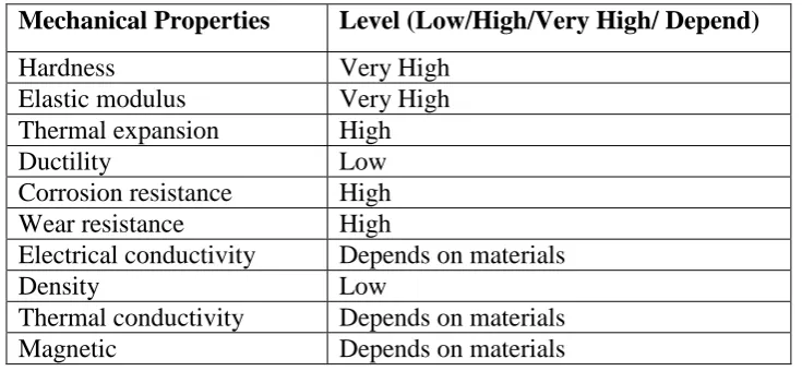
[image:21.595.136.504.190.360.2]ceramics are tough, strong and stiff which can retain their properties at high temperature about 600 °C. Besides, Ćurković et al. (2011) also indicates that ceramic is brittle, high wear and corrosive resistance, and have low density. The general properties of ceramic are shown in Table 2.1.
Table 2.1: The general properties of ceramic (The American Ceramic Society, 2014).
Mechanical Properties Level (Low/High/Very High/ Depend)
Hardness Very High
Elastic modulus Very High
Thermal expansion High
Ductility Low
Corrosion resistance High
Wear resistance High
Electrical conductivity Depends on materials
Density Low
Thermal conductivity Depends on materials
Magnetic Depends on materials
5.2 Casting Methods
8
2.2.1 Slip Casting
Most widely used in industry field of ceramic products is slip casting. This casting is a common traditional wet consolidation technique which will provide a uniform green compact through smooth particle movement and arrangement throughout the casting method (Kim et al., 2015). According to Zhang et al. (2015), an experiment was done to identify the optimum slurry composition to prepare the qualified green BaCo0.7Fe0.2Nb0.1O3-δ(BCFNO) tubular membrane using slip casting methods. The
[image:22.595.222.413.316.494.2]closed one ended membrane tubes were produced by steps in Figure 2.1. The aqueous slurry was prepared and poured into plaster moulds. Then, the green tubes were dried and sintered at high temperature for dwelling time.
Figure 2.1: Schematic diagram for slip casting of BCFNO tube (Zhang et al., 2015).
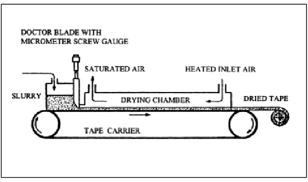
2.2.2 Tape Casting
9
[image:23.595.165.473.192.374.2]electrolytes, ceramic substrates and solid oxide fuel cells (SOFCs). The alumina ceramics can be strengthened for improving its’ reliability by using tape casting as proved by Yu et al. (2015). Furthermore, Nie et al. (2015) explains the fabrication of SOFC single cells is scalable and cost effective while applying tape casting and co-firing methods.
Figure 2.2: A continuous tape caster (Tok et al., 1999).
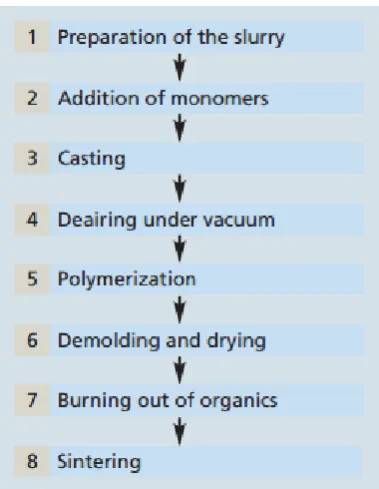
2.2.3 Gelcasting
10
Figure 2.3: The flowchart of the gelcasting method(Dresden, 2013)
Guo & Technology (2011) indicates that the ceramic defects such as cracking and shrinkage in ceramic body were reduced while using gelcasting technique. The high solid content of the ceramic suspension with low viscosity and the higher solid loading was desired in gelcasting to have good performance to produce good quality of ceramic products. However, in gelcasting process will face difficulty to cast the ceramic slurry into the mould as the slurry having high viscosity. Therefore the monomer solution is added to attaining flowable of slurry.
2.2.4 Investment Casting