PATTERNS MADE OF INLAY WAX, EPOXY RESIN, AUTO-POLYMERISED PATTERN RESIN AND LIGHT CURED PATTERN RESIN.
Dissertation submitted to
THE TAMILNADU Dr. M.G.R. MEDICAL UNIVERSITY In partial fulfillment for the Degree of
MASTER OF DENTAL SURGERY
BRANCH I
ON MARGINAL FIT OF FULL CROWN PATTERNS MADE OF INLAY WAX, EPOXY RESIN, AUTO-POLYMERISED PATTERN RESIN AND LIGHT CURED PATTERN RESIN ” is a bonafide record of work done by
Dr. P. MEGASHYAM under my guidance and to my satisfaction during his postgraduate study period between 2013-2016.
This dissertation is submitted to THE TAMILNADU Dr. M.G.R. MEDICAL UNIVERSITY, in partial fulfillment for the award of the degree of Master of Dental Surgery in Prosthodontics and Crown and Bridge, Branch I. It has not been submitted (partial or full) for the award of any other degree or diploma.
_________________________________ _______________________________
Dr. ANJANA KURIEN, MDS, Dr. V.R.THIRUMURTHY, MDS,
________________________________
Dr. V. Prabhakar, MDS,
Date:
Place: Coimbatore
Principal,
Sri Ramakrishna Dental College and Hospital,
Coimbatore.
Vice Principal, Professor and Head,
Dept. of prosthodontics including crown and
bridge and Implantology,
Sri Ramakrishna Dental College and Hospital,
Coimbatore.
Coimbatore.
Professor and Guide,
Dept. of prosthodontics including crown and
bridge and Implantology,
Sri Ramakrishna Dental College and Hospital,
“No one is more cherished in this world than someone who lightens the burden of another.”
Dear teachers, you are the best because you brought out the best in me. I owe you a debt of gratitude
for all that you have done for me, thank you.
As a sense of triumph is very much justified at this stage of completion of my
dissertation, even more so is a sense of gratitude to my beloved parents, mentors, all
my peers and well wishers.
Words are not sufficient to express my sincere and humble gratitude to my
renowned and respected teacher, Professor and Head of the Department,
DR. V. R. Thirumurthy, for his valuable guidance, keen personal interest and unsurmountable help in carrying out this study from its inception to completion.
I gladly utilize this opportunity to express my deep sense of gratitude and
indebtedness to my respected teacher and guide, Professor Dr. Anjana Kurien, whose incessant encouragement, constructive criticism and valuable suggestions greatly
helped in improving the quality of my study.
I am very deeply indebted to Dr. Bindhoo, for her patience, effective and timely advice, her helpful nature, most valuable suggestions, personalized attention and
constant encouragement and an everlasting inspiration which enabled me to complete
my study.
I am immensely indebted to my college Sri Ramakrishna Dental College and Hospital, Lt. Gen Dr. Murali Mohan, Professor and Director; Dr. V. Prabhakar, Principal, for being a helping hand in providing the required facilities and
infrastructure.
I would like to thank other staff members of the Department of Prosthodontics for
all the help they provided me during the period of my post-graduation.
I sincerely thank Dr. Deeptha Kumaran and Dr. Priyanka Ravi, Public health dentist for helping me with the statistical analysis and interpretation.
I would like to extend my heartfelt thanks to my seniors Dr. Sivakumar, Dr. Geetha, Dr. Niranjana, Dr. Manivasagan, Dr. Muthukumar and Dr.
Padmashini for their support and guidance.
I am grateful to my colleagues Dr. Kumaran and Dr. Vishnu Manohar for the help extended by them throughout this work.
My sincere appreciation to my juniors Viji, Geetha and Priyanka for their timely help. A special note of appreciation to my juniors Monica, Parvathi and Sruthi for their cooperation.
I owe a lot to my Parents, Brothers and all my Friends who have been on my side in times both good and bad and boosted my morale constantly.
CONTENTS
TITLE
PAGE No
1. INTRODUCTION 1
2. AIMS AND OBJECTIVES 3
3. REVIEW OF LITERATURE 4
4. MATERIALS AND METHODS 15
5. RESULTS 35
6. DISCUSSION 49
7. SUMMARY & CONCLUSION 58
MOD Mesial Occlusal Distal
RTV Room Temperature Vulcanizing UTS Ultimate Tensile Strength
CAD/CAM Computer Aided Design / Computer Aided Milling UDMA Urethene Dimethacrylate
PMMA Polymethyl Methacrylate
BIS-GMA Bisphenol –A- Glycidyl Dimethacrylate ARP Acrylic Resin Patterns
CAL Corono Apical Length AD Apical Diameter
AISI American Iron and Steel Institute SEM Scanning Electron Microscope
SPSS Statistical Package for Social Science ANOVO Analysis Of Variance
FIGURE
NO. TITLE
PAGE NO
1 3D image of Metal die 18
2 Armamentarium used for the study 25
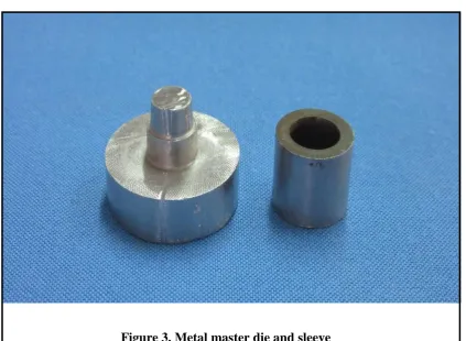
3 Metal master die and sleeve 25
4 Custom tray for master die 26
5 Impressions of master die 26
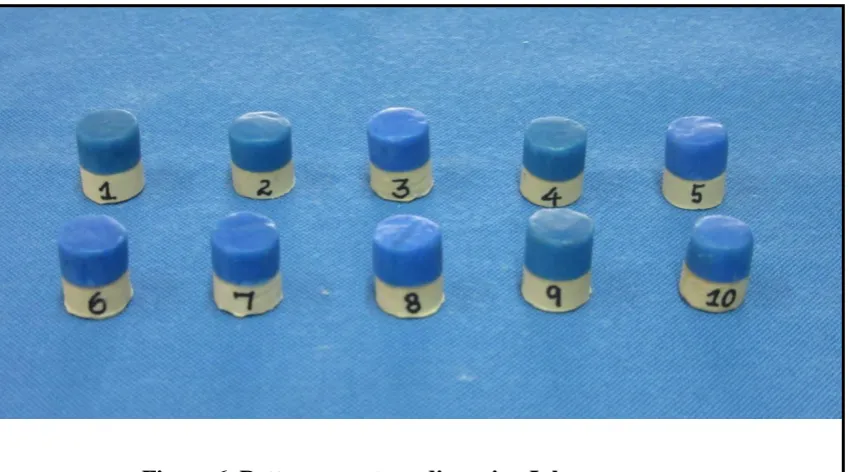
6 Patterns on stone dies using Inlay wax 27
7 Patterns on stone dies using Auto-polymerized pattern
resin 27
8 Patterns on stone dies using Light cure modelling
material 28
9 Patterns on stone dies using Epoxy resin 28
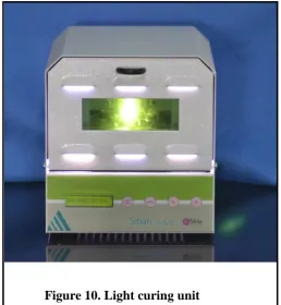
10 Light curing unit 29
11 Gold sputtering device 29
12 Scanning electron microscope 30
13
Photograph showing the vertical marginal discrepancy of
Inlay wax pattern at 1 hr 31
14
Photograph showing the vertical marginal discrepancy of
15
Photograph showing the vertical marginal discrepancy of
Auto-polymerized resin pattern at 1 hr 32
16
Photograph showing the vertical marginal discrepancy of
Auto- polymerized resin pattern at 24 hrs 32 17
Photograph showing the vertical marginal discrepancy of
Light cure pattern at 1 hr 33
18
Photograph showing the vertical marginal discrepancy of
Light cure pattern at 24 hrs 33
19
Photograph showing the vertical marginal discrepancy of
Epoxy resin pattern at 1 hr 34
20
Photograph showing the vertical marginal discrepancy of
Epoxy resin pattern at 24 hrs 34
LIST OF DIAGRAMS
DIAGRAM NO
TITLE PAGE
NO
[image:8.595.103.525.70.432.2]TABLE
NO
TITLE
PAGE
NO
1. Materials used in study 15
2. Equipment used in study 16
3. Marginal discrepancy of patterns fabricated using inlay pattern wax (Group I) at 1 hr and 24 hrs
36
4. Marginal discrepancy of patterns fabricated using Auto-polymerized pattern resin (Group II) at 1hr and 24 hrs
37
5. Marginal discrepancy of patterns fabricated using Light-curing modelling material (Group III) at 1hr and 24 hrs
38
6. Marginal discrepancy of patterns fabricated using Epoxy resin (Group IV)at 1hr and 24 hrs
39
7. Descriptive for various groups at 1hr and 24 hrs 41 8. Comparison between different groups at 1 hr 42 9. Comparison between different groups at 24 hrs 42 10. Post hoc analysis between different groups at 1 hr 43 11. Post hoc analysis between different groups at 24 hrs 44 12. Comparison in individual groups between 1 hr and 24
hrs
S.No
GRAPHS
PAGE
NO
1. Mean marginal discrepancy of the groups at 1 hr 46 2. Mean marginal discrepancy of groups at 24 hrs 46 3. Comparison between marginal discrepancy of groups at1 hr and 24 hrs
47
4. Line diagram showing mean marginal discrepancy of the materials at 1 hr and 24 hrs
The lost wax technique advocated by Taggart (1907) is the widely used
method for fabrication of cast restoration15. In this casting technique, a pattern,
usually made of wax or resin, is utilized in forming the inside cavity of a refractory
mold.
The precision fit of casting depends on the accuracy of wax pattern,
storage time and media, and optimum expansion of investment material39. A
restoration is predictable when its marginal gap is minimum, which depends on the
marginal fit of the pattern.
Precise marginal seating is more important in dental restoration to fulfil
biological, physical and cosmetic requirement that provides optimum function,
esthetics and long-term success in the oral cavity.
Increased marginal discrepancies expose the luting material to the oral
environment, thus leading to cement dissolution and microleakage. The cement seal
becomes weak, permits the percolation of bacteria, and can cause inflammation of the
vital pulp15.
One of the disadvantages of conventional pattern material is their dimensional
inaccuracy.
In most instances a considerable amount of time elapses between the
fabrication of the pattern and initiation of the investment and casting process.
Controlled manipulation and understanding of the dimensional changes of wax and
resin may lead to an acceptable pattern, but distortions caused by prolonged storage,
high thermal expansion and contraction, visco-elastic behaviour under load and
manipulation temperatures before investing has been shown to affect marginal
Although attempts have been made to improve them, the commonly used
dental waxes are not yet entirely free of their known drawback of large and perhaps
uncontrollable thermal expansion.
Shrinkage of resinous die materials during setting reaction limits their
acceptance, even though these materials show several advantages compared to wax
patterns.
Auto-polymerized acrylic resins have been used for castings requiring greater
dimensional stability. Auto-polymerization reduces the amount of time available for
manipulation, but the rigidity and hardness of the auto-polymerized resin allow for
shaping to be performed with abrasive instruments. However, the major disadvantage
of acrylic resin is its high polymerization shrinkage37.
To overcome the drawbacks of these materials, newer Light-curing pattern
material has been introduced which is reported to have better fit and stability after
light polymerization. Limited available literature quotes that the advantages of these
light-curing resins are their low polymerization shrinkage, good dimensional stability,
easy to use, less chair time, and absence of residue on burn-out37.
In addition to these materials, epoxy resins which was earlier used as die
materials is now marketed as pattern material after modification of chemical
composition. The dimensional accuracy of this epoxy resin material is not reported in
literature.
Hence, this study was designed to compare the marginal accuracy of 4 pattern
materials (Inlay wax, Auto-polymerized pattern resin, Epoxy resin and Light cure
AIMS:
The study is aimed at determining marginal fit of full crown patterns made of
inlay wax, epoxy resin, auto-polymerised pattern resin and light cured pattern resin
after 1 hour and 24 hours storage time.
The null hypothesis H01 of the study assumes that there is no difference in
marginal fit among the pattern materials.
The null hypothesis H02 of the study surmises that the storage time does not
influence the marginal fit of the crown patterns.
OBJECTIVES:
1. To determine the vertical marginal discrepancy of inlay wax pattern on storage
at 1 hour and 24 hours.
2. To determine the vertical marginal discrepancy of epoxy resin patterns on
storage at 1 hour and 24 hours.
3. To determine the vertical marginal discrepancy of auto-polymerised resin
patterns on storage at 1 hour and 24 hours.
4. To determine the vertical marginal discrepancy of light cured resin patterns on
storage at 1 hour and 24 hours.
5. To compare the vertical marginal discrepancy values obtained for the inlay
wax patterns, epoxy resin patterns, auto-polymerised resin patterns and light
Souder W, Paffenbarger GC34 (1940) observed that waxes exhibit visco -elastic behaviour under load, and manipulation temperatures which are close to their
melting temperatures. Thus their mechanical properties are markedly temperature and
time dependent.
Jorgensen KD, Ono T14 (1984) appraise the effect of type of wax, the thickness of the pattern, the method of wax manipulation and the effect of storage time on the
distortion of full crown patterns. They concluded that because of the inherent property
of distortion, inlay wax was an inadequate material for pattern production in
techniques requiring high precision.
Zeltser C, Lewinstein I, Grajower R42 (1985), evaluated the fit of patterns removed from the die for investment following pressure application after remodelling.
Various loads were placed on the pattern after its margin was remodelled. The
patterns were replaced on the die with a load of 50 gm before investment. For loads of
0, 250, and 1000 gm, the average elevation of the pattern on the die was found to be
greater by 29, 56, and 19 pm, respectively, than before removal from the die.
Repetitive loading showed that the plastic deformation in wax was less in the second
than in the first cycle for a specific load. This decrease in plastic deformation may
explain the improved adaptation of the pattern after a load of 1000 gm.
Koumjian JH, Holmes JB16 (1990), conducted a study to evaluate the marginal accuracy of seven commercially available resins by using an established indirect
Eight specimens of each material were tested under three conditions: immediately
after polymerization, after 1 week of dry storage, and after 1 week of storage in room
temperature water. Seven materials used in the study are Snap (polyethyl
methacrylate), Trim (polyvinylethyl methacrylate), Tru-Kit (methyl methacrylate),
Protemp (Bis-aryl-composite), Triad (light-activated composite resin), Duralay
(methyl methacrylate), Cold Pat (polymethyl methacrylate). They concluded that the
best result was obtained with Duralay resin, followed by Cold Pat and Snap resins.
These three materials had significantly less marginal discrepancy compared with the
other resins tested. All of the materials showed evidence of continued polymerization
shrinkage after storage in air for a week. Water absorption compensated for
polymerization shrinkage in all of the materials except Trim and Protemp resins.
Philippe, M., Jean-Pierre, O., Jean-Marc, M., Belser, Urs C25 (1990), evaluated dimensional changes of two self-curing acrylic resins marketed as pattern
and index material. Early volumetric changes were measured with a dilatometer and
late linear changes were recorded with an inductive transducer. After 24 hours the
volumetric shrinkage was 7.9% for Duralay resin and 6.6% for Palavit G resin; 80%
of the change appears before 17 minutes at room temperature. They concluded that
the shrinkage was significantly increased when the proportion of powder in the mix
was diminished.
Ness EM, Nicholls JI, Rubenstein JE, Smith DE et al22 (1992), conducted an in vitro study to determine the accuracy of three acrylic resins used in the
fabrication of patterns for implant superstructures. The three acrylic resins compared
GC Pattern Resin, a poly(methyl methacrylate). He concluded that GC Pattern Resin
and Relate produced significantly smaller displacements than did Duralay.
Kotsiomiti E, Kaloyannides A D15(1994) compared the values of the critical physical properties, flow and linear thermal expansion, of crown pattern waxes with
those reported by previous investigators. Measurements were conducted at
temperature range of 27 0C to 52 0C. They observed that the rate of expansion changes
with increase in temperature of waxes from 1-1.5% or more as the temperature was
increased from 270C - 47 0C and most materials flow by 61%-82% at temperature of
470C - 520C. They concluded that the expansion would vary with the changes in
temperature as crystalline structure material changes with the increase in temperature.
Lefebvre C, Schuster GS18 (1994) conducted a study on biocompatibility of visible light-cured resin systems in prosthodontics. Their study focussed on three
widely used denture base materials, Triad, Extoral, and Astron LC Hard. Triad is a
light-polymerized resin, whereas Extoral and Astron resins are polymerized by a
combination of visible-light and chemical polymerization. It was found that visible
light-polymerized denture base resin systems affect various cell metabolic processes
with varying degrees of cytotoxicity. The dual polymerization resins appear to be less
toxic than those polymerized only by light.
Miehio Ito, Toshio Yamagishi, Yoshikioshida, Carlos A. Munoz et al20 (1996) evaluated the relationship between flow characteristics, bending strength, and softening temperature of paraffin and dental inlay waxes to casting shrinkage and they
a low flow wax is used or if there is a need for a thick pattern, the size of the casting
ring should be increased.
Iglesias A, Powers JM, Pierpont HP13 (1996) conducted a study on marginal fit of MOD inlay and full crown patterns. Patterns were fabricated from inlay wax,
Auto-polymerized pattern resin, Light-curing diacrylate resin pattern materials using
incremental and bulk techniques. With the incremental technique, the Light-curing
diacrylate resin patterns and inlay wax patterns had statistically significant smaller
gaps than the Auto-polymerized pattern resin, whereas no significant change noticed
in bulk technique.
Diwan R, Sadiq W07 (1997) conducted a study on effect of storage time of the wax pattern for removable partial denture before casting and the influence of the
palatal major connector design on the accuracy of its fit on the master cast. Forty-two
frameworks were prepared with two designs of major connectors, which were divided
into three subgroups according to the storage time of the wax patterns: 24 hours, 1
week, and 1 month. It was found that in both framework design groups, there was a
significant deterioration in fit (p <0.0005) of the major connectors with the increase in
storage time of their wax patterns on their respective refractory casts. Discrepancies in
the fit of the connectors to their respective casts were measured at specific locations
for both connector designs. The greatest discrepancies appeared at the middle sections
of the connectors more than at the lateral sections.
parameters used in low pressure injection moulding. Wax patterns are produced using
both the hard (polyurethane mould) and soft (RTV mould) tools. Based on the study
on optimisation of the injection parameters, it is found that using a lower pressure
with higher temperature for the polyurethane mould will produce an accurate patterns
provided that appropriate care is taken while choosing the holding time. A short
holding time will yield a more accurate pattern, but too short a holding time will cause
distortion when removing it from the mould, as it is too soft. Too long a holding time
will cause more shrinkage. For the silicone mould, only the injection temperature has
an effect on the dimensions of the wax patterns. The dimensional errors incurred
during dipping are also measured and found that, generally there is a reduction of 0.2–
0.4% in dimension.
Yiu CKY, King NM, Pashley DH, Suh BI, Carvalho RM, Carrilho MRO et al41 (2004) evaluated the change in the ultimate tensile strength (UTS) of five polymerized resin blends of increasing hydrophilicity, after ageing in distilled water
or silicon oil. The UTS of the experimental specimens were determined after 1, 3, 6
and 12 months of ageing in water or oil. Significant reduction (p<0:01) in UTS was
observed in Groups II–V resins after 12-month storage in water, while the most
hydrophobic Group I resin showed no significant change (p > 0:05) in the same
period.
Abdullah MA, Suiaiman A, Jabab A01 (2005) conducted a study to evaluate the marginal fit of full crown patterns made from wax, auto-polymerized and visible
light cured acrylic resin materials. They found that patterns made from each of the
marginal fit at 1 hour than at 24 hours after fabrication. Under the two storage
conditions, the wax patterns showed the greatest marginal gap followed by visible
light-cure resin and auto-polymerizing acrylic resin.
Nivedita S, Prithviraj DR23 (2006), conducted a study to compare the vertical marginal discrepancy of provisional restorations fabricated using light
polymerized composite resin by direct technique and provisional restorations
fabricated using auto polymerized resin by direct and indirect technique. They
concluded that the vertical marginal discrepancy of the provisional restorations
fabricated using light cured composite resins by direct technique was least and had a
better marginal fit compared to the provisional restorations fabricated using
auto-polymerized resin by direct and indirect technique. The light cured resin could be a
better material used to fabricate provisional restoration with an improved marginal
adaptation.
Truffier-Boutry D37 (2006) conducted a study on the polymerization characteristics like flexural strength, modulus of elasticity, water sorption and
volumetric shrinkage of light and auto-curing resins. With respect to the
polymerization properties evaluated in this study, the light-curing resins reacted
similar to auto-polymerizing resin or even surpassed them.
Ghanbarzadeh J08 (2007) compared the effect of storage time and conditions on dimensional stability of acrylic patterns and the best condition for storing Duralay
post core patterns. He divided the specimens into three groups. They were stored in
at 4°C, respectively. It was observed that the best condition for storing Duralay
pattern resin was 100% humidity at 25°C for 24 hours. Storage time was also shown
to have a negative effect on dimensional stability of Duralay post core patterns in all
three groups.
Prisco R, Cozzolino G, Vigolo P27 (2008) conducted a study to determine if retarding the setting reaction during polymerization and altering the base-to-catalyst
ratio, as suggested by previous studies, can be recommended for resinous die
materials to reduce the inaccuracy in transferring the spatial position of teeth or
implants from the oral cavity to the master cast. The epoxy resin die material tested in
this research did not improve its dimensional accuracy following retarding
polymerization or modifying the epoxy resin base/activator ratio.
Bemblage O, Karunakar DB02 (2011) performed a study to produce a wax blend which could offer better surface finish, minimum shrinkage and moderate
hardness. They concluded that, wax blend with proportion of 50% paraffin wax, 30%
bees wax, 20% montan wax and 0% carnauba wax gives the better results of linear
shrinkage, volumetric shrinkage and surface roughness.
Gomaa M, Fahmy A10 (2012) conducted a study to evaluate effect of different storage conditions and time before wax elimination on the marginal fit &
surface adaptation (cement space) of base metal alloy crowns invested in
phosphate-bonded investment material. Invested wax patterns that had been stored for 36 hours
comparison with the control group especially at occlusal area. Storing the wax
patterns in air for different periods had no statistical difference from control group.
Rajagopal P, Chitre V, Aras MA28 (2012) investigated the marginal accuracy of patterns fabricated from an inlay casting wax, an auto-polymerized
pattern resin and a light polymerized pattern resin on storage off the die for varying
time intervals, and commenced that the inlay wax showed a significantly greater
marginal discrepancy at the 12 and 24 hour intervals. The auto-polymerized resin
showed an initial (at 1 hour) marginal discrepancy slightly greater than inlay wax, but
showed a significantly less marginal gap (as compared to inlay wax) at the other two
time intervals. The light-cured resin proved to be significantly more dimensionally
stable, and showed minimal change during the storage period.
Vojdani M, Torabi K, Farjood E, Aar K et al38 (2013) evaluated the marginal and internal fit of copings cast from CAD/CAM and conventional fabricated
wax-patterns. They found that conventional method of wax-pattern fabrication
produced copings with significantly better marginal and internal fit than CAD/CAM
(machine-milled) technique.
Sharma S, Jain A, Balasubramanian R, Alavandar S, Manoharan P et al32 (2013) conducted a study to compare the flexural strength of provisional restorative material fabricated using light polymerized composite resin and auto polymerized
resin. It was found that the flexural strength of provisional restorative specimen fabricated using Poly Methyl Methacrylate (PMMA-134.1 Mpa) was significantly
urethane dimethacrylate (UDMA-107.8 Mpa). They concluded that the flexural
strength of polymethyl methacrylate (PMMA) is comparatively better than the
flexural strength of Urethane dimethacrylate (UDMA). PMMA could be a better
provisional restorative material for an extended period, when the patient exhibits
parafunctional habits, or when long-span prosthesis is planned.
Sushma R, Farias A, Soni R36 (2014) evaluated the vertical marginal accuracy of complete cast crowns using Inlay Pattern Wax; Auto-polymerized Pattern
Resin and Light Cured Modeling Resin and cast immediately. They found that inlay
wax can still be the pattern material of choice to produce a casting with minimal
marginal discrepancy with added advantages of being user friendly and cost effective.
Nejatidanesh F, Lotfi H R, Savabi O21 (2014) conducted a study to compare the marginal accuracy of interim restorations made with 4 interim materials. A direct
technique was used to fabricate 44 interim restorations with 4 materials: Protemp 3
Garant, Trim II, Tempron, and Acropars. The mean marginal discrepancies of
Protemp 3 Garant, Trim II, Tempron, and Acropars were 0.059, 0.063, 0.068, and
0.102 mm, respectively. Thus they found that the interim restorations made from the
Bis-GMA and conventional acrylic resins tested produced comparable marginal fit.
Michalakis KX, Kapsampeli V, Kitsou A, Kirmanidou Y, Fotiou A, Pissiotis AL, et al19 (2014) conducted a study to evaluate the marginal accuracy of 4 inlay casting waxes on stone dies, titanium and zirconia abutments and to correlate the
waxes. Stone dies provided wax copings with the best marginal integrity, followed by
titanium and zirconia abutments.
Gibbs, S.B., Versluis, A., Tantbirojn, D., Ahuja, S09 (2014) conducted a study to compare the polymerization shrinkage of photopolymerizing pattern resins
with autopolymerizing pattern resins. Two autopolymerizing (DuraLay, GC Pattern
resin) and 2 photopolymerizing (Primopattern LC Gel, Primopattern LC Paste) pattern
resins were tested. The sample size was 10 for each group. Polymerization shrinkage
was determined by measuring the change in area dimensions with image analysis. The
volumetric shrinkage values for GC Pattern Resin were 5.72 ±0.89; for DuraLay, 5.07
±1.36; for Primopattern LC Gel, 5.42 ±1.83; and for Primopattern LC Paste, 7.43
±0.62. Based on these values they concluded that the volumetric shrinkage of the
Primopattern LC Paste was significantly higher than that of the other 3 materials. Also
the photopolymerizing pattern resin in gel form (Primopattern LC Gel) had a similar
shrinkage value to the autopolymerizing pattern resins (DuraLay and GC Pattern
Resin). They also quoted that the photopolymerizing pattern resin in paste form
(Primopattern LC Paste) had shrunken significantly more than the other 3 materials
tested.
Shaikh SA, Chandra PK , Lekha K, Rao M, Taneja P et al31 (2014) figured out the mean marginal and internal discrepancy of the castings fabricated using the
inlay wax was the least, and discrepancy of the castings fabricated using the Light
Cured Wax was the highest. The castings fabricated using the Pattern Resin had better
marginal and internal accuracy than the castings fabricated using Light Cured Wax.
marginal and internal accuracy compared to the castings fabricated using the Inlay
wax.
Sabouhi M, Nosouhian S, Dakhilalian M, Davoudi A et al30 (2015) conducted a study to compare dimensional changes of acrylic resin patterns (ARP) in
three different storing environments. Finally dimensional changes in coronoapical
length (CAL), coronal (CD) and apical diameter (AD) of APRs were measured in 7
consecutive times (immediately after polymerization, 1, 2, 4, 8, 24, 48 hours later).
After 24 hours, the ARPs, which were stored in air, contracted 0.07, 0.06 and 0.12
mm in AD, CD and CAL; the ARPs, which were stored in water, showed 0.03, 0.06
and 0.12 mm decrease in AD, CD and CAL; But the ARPs, which were stored in
NaOCl 5%, showed significant expansion in AD, CD and CAL (0.03, 0.06 and 0.10
mm). They concluded that it would be better not to use NaOCl for disinfecting; also
the best time for storing APRs is 8 hours for water and 2 hours for air environments
The present laboratory study was carried out to determine and compare the
vertical marginal discrepancy for the patterns fabricated using Inlay pattern wax,
[image:29.595.103.533.193.767.2]Auto-polymerized pattern resin, Light-curing modeling material and Epoxy resin.
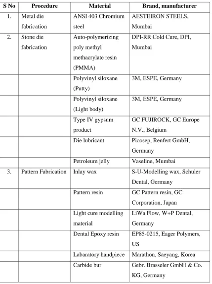
Table 1: Materials
S No Procedure Material Brand, manufacturer
1. Metal die
fabrication
ANSI 403 Chromium
steel
AESTEIRON STEELS,
Mumbai
2. Stone die
fabrication
Auto-polymerizing
poly methyl
methacrylate resin
(PMMA)
DPI-RR Cold Cure, DPI,
Mumbai
Polyvinyl siloxane
(Putty)
3M, ESPE, Germany
Polyvinyl siloxane
(Light body)
3M, ESPE, Germany
Type IV gypsum
product
GC FUJIROCK, GC Europe
N.V., Belgium
Die lubricant Picosep, Renfert GmbH,
Germany
Petroleum jelly Vaseline, Mumbai
3. Pattern Fabrication Inlay wax S-U-Modelling wax, Schuler
Dental, Germany
Pattern resin GC Pattern resin, GC
Corporation, Japan
Light cure modelling
material
LiWa Flow, W+P Dental,
Germany
Dental Epoxy resin EP85-0215, Eager Polymers,
US
Labaratory handpiece Marathon, Saeyang, Korea
Carbide bur Gebr. Brasseler GmbH & Co.
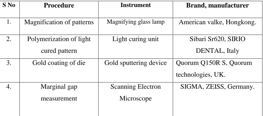
Table 2: Equipment
S No Procedure Instrument Brand, manufacturer
1. Magnification of patterns Magnifying glass lamp American valke, Hongkong. 2. Polymerization of light
cured pattern
Light curing unit Sibari Sr620, SIRIO
DENTAL, Italy
3. Gold coating of die Gold sputtering device Quorum Q150R S, Quorum
technologies, UK.
4. Marginal gap
measurement
Scanning Electron
Microscope
Methodology
STUDY DESIGN:
Fabrication of a standardized metal die simulating a prepared molar crown
GROUP A GROUP B GROUP C
10 stone dies Numbered 1-10
Gold coating the surface of stone dies and patterns using gold sputtering device
Measurement of marginal discrepancy using scanning electron microscope at 1hr and 24 hr
RESULTS
STATISTICAL ANALYSIS
Fabrication of 40 acrylic custom trays that fits the metal die
Making impression of the metal dies using custom trays with polyvinyl impression material
Impression poured with type-IV dental stone and 40 stone dies were obtained
GROUP D
10 stone dies Numbered 11-20
10 stone dies Numbered 21-30
10 stone dies Numbered 31-40
Pattern fabrication using Inlay wax
Pattern fabrication using Autopolymerising
resin
Pattern fabrication using Light Cure modelling material
Pattern fabrication using
Fabrication of the master die:
A standardized metal die simulating a prepared molar crown was milled from
AISI 403 chromium steel. The die was milled with the following dimension (diagram
1, figure 1) with a cylindrical base and a cylindrical substructure.
1. Occluso-gingival height - 7.0 mm
2. Taper - 5°
3. Minor diameter - 7.28 mm
4. Major diameter - 8.0 mm
5. Shoulder finish line - 1.0 mm
6. Base height - 5.0 mm
7. Base diameter - 9.0 mm
8. Substructure height - 8.0 mm
9. Substructure diameter - 20.0 mm
Diagram 1. Scheme of sleeve and metal die
3 1
5
6
7
8
[image:32.595.96.548.224.754.2]9
Figure 1. 3D image of Metal die
An orientation notch was made on the axial margin of the die for proper
seating of the pattern.
In order to standardize the construction of the patterns a cylindrical stainless
steel sleeve with an internal diameter of 9.0 mm and 9.0 mm in height was prepared
so that it fits exactly around the base of the die over the substructure.
Fabrication of the specimens:
40 Autopolymerising acrylic resin custom impression trays (figure 3) were
fabricated over master die after adapting 2mm of wax spacer completely around the
die and base. Custom trays were fabricated such that it surrounds the base and ends
over the top of substructure that acts as a stopper for the tray. They were stored at
room temperature for a minimum of 24 hours before use01. Impressions of the metal
master die was made in addition silicone using the putty- wash technique (figure 4).
Impressions were poured after 1 hour with vacuum mixed Type IV dental stone to
obtain stone dies for preparation of patterns. The stone dies were allowed to set for 1
hour35. They were verified under normal vision and dies with porosities were
discarded. A total of 40 individual stone dies were fabricated. The dies were then
lubricated with a oil base die lubricant and pattern materials were applied to the
gypsum dies by the same operator using incremental or bulk placement techniques,
The specimens were divided into 4 groups of 10 each:
Group I: Consisted of 10 stone dies numbered from 1-10, over which the patterns
were prepared using Inlay pattern wax (figure 5).
Group II: Consisted of 10 stone dies numbered from 11-20, over which the patterns
were prepared using Auto-polymerized pattern resin (figure 6).
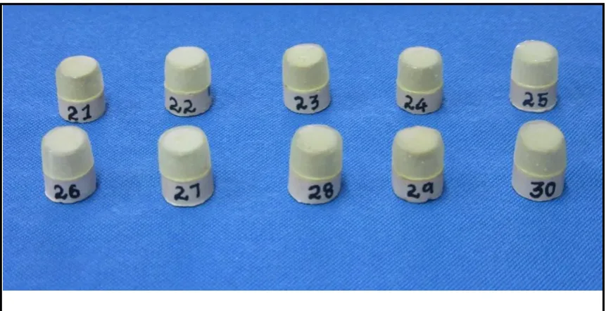
Group III: Consisted of 10 stone dies numbered from 21-30, over which the patterns
were prepared using Light-curing modeling material (figure 7).
Group IV: Consisted of 10 stone dies numbered from 31-40, over which the patterns
were prepared using Dental epoxy resin (figure 8).
Preparation of the patterns using 4 different pattern materials.
1. Inlay Pattern wax.
Inlay wax (S-U-Modelling wax, Schuler Dental, Germany) with solidus
temperature of 640C was melted in an electrically controlled wax bath at 90°C
according to manufacturer’s instruction. The stone dies were lubricated with a oil base
separating medium (Picosep, Renfert GmbH, Germany) and the sleeve was lubricated
with petroleum jelly (Vaseline, Mumbai). The sleeve was then fit on the stone die.
Molten wax was poured around the stone die to the height of the metal sleeve that was
enclosed axially. The wax patterns were allowed to cool to room temperature for 10
min and residual wax was carved by hand. Each crown pattern was placed on its
corresponding die and examined carefully. The marginal wax was reflowed and
readapted to confirm to the margins. 10 wax patterns were prepared in the similar way
2. Auto-polymerized pattern resin.
A thin layer of separating medium (Picosep, Renfert GmbH, Germany) was applied
onto the gypsum dies and thereafter the dies were allowed to dry to facilitate easy
removal of patterns. The sleeve was lubricated with petroleum jelly (Vaseline,
Mumbai). According to manufacturer’s instruction, Auto-polymerized pattern resin
(GC Pattern resin, GC Corporation, Japan) was applied over the stone dies. Fine brush
dipped in monomer when contacted the powder formed a bead of acrylic material.
This was applied incrementally using the brush on technique over the stone die. The
length and width of the pattern was maintained using the sleeve. The excess resin in
the form of fins were trimmed carefully using a carbide bur (H281, Gebr. Brasseler
GmbH & Co. KG, Germany) in a slow-speed hand piece (Marathon, Saeyang, Korea)
to exact dimensions13. 10 resin patterns were prepared as described on stone dies
numbered from 11-20.
3. Light-curing modeling material.
The light-curing modeling material (LiWa Flow, W+P Dental, Germany) was
applied onto the gypsum stone dies following the application of a thin layer of
separating medium (Picosep, Renfert GmbH, Germany) on the dies. The sleeve was
lubricated with petroleum jelly (Vaseline, Mumbai). The pattern material was layered
and polymerized incrementally for a initial period of 2 min in a light curing unit
(figure 9) using visible light of wavelength 320-550nm maintaining the constant
length and width of the pattern using the sleeve. Care was taken not to touch the
polymerized resin surface as it would result in removal of dispersion film formed.
This film is essential for the bonding of the subsequent increment. After the final
were generally required as each increment was sculpted prior to polymerization.
When required, trimming was done with a carbide bur (H281, Gebr. Brasseler GmbH
& Co. KG, Germany) in a slow speed hand piece (Marathon, Saeyang, Korea). 10
light cure patterns were fabricated as discussed on stone dies numbered from 21-30.
4. Epoxy resin.
Separating medium (Picosep, Renfert GmbH, Germany) was applied onto the
stone dies and sleeve was lubricated with petroleum jelly (Vaseline, Mumbai). The
Epoxy resin material (EP85-0215, Eager Polymers, US) containing resin (part A) and
hardener (part B) were mixed in a silicone cup in the ratio of 10:1 according to
manufacturer’s instruction and applied using a fine brush over the stone dies. Axial
surface was moulded using the sleeve and complete polymerisation occured in 6min.
The excess resin was trimmed carefully using a carbide bur (H281, Gebr. Brasseler
GmbH & Co. KG, Germany) in a slow-speed hand piece (Marathon, Saeyang, Korea)
to exact dimensions. 10 Epoxy resin patterns were fabricated in the similar way on
stone dies numbered from 31- 40.
On completion all the patterns were visually inspected with a 3X magnifying
lens to ensure proper marginal adaptation. Specimens with high marginal discrepancy
were discarded and the procedure was repeated. The specimens were then stored for 1
hour at room temperature so as to simulate the regular laboratory condition. After 1
hour from the beginning of fabrication, the patterns were subjected to image analysis.
The patterns were then allowed to remain at room temperature for another reading at
Image analysis.
In order to accurately measure the marginal gap between the stone dies and
patterns scanning electron microscope (SEM) was used and the gap was measured in
microns.
The scanning electron microscope (SIGMA, ZEISS, and Germany) uses a
focused beam of high-energy electrons to generate a variety of signals at the surface
of solid specimens. The signals that are received back from electron-sample
interactions reveal information about the sample including external morphology
(texture), chemical composition, crystalline structure and orientation of materials
making up the sample. In most applications, data are collected over a selected area of
the surface of the sample, and a 2-dimensional image is generated that displays spatial
variations in these properties.
The surface of stone dies and patterns were gold coated using the Gold
Sputtering Device (figure 10) that enables conduction of electrons for visualization of
margins. A point was marked near the finish line at the junction of stone dies and
patterns in all the specimens. They were subsequently scanned using the Scanning
Electron Microscope (figure 11) and 2 readings within the focus of single magnified
marked point were measured and named as Pa1 and Pa2.
The marginal discrepancy of the patterns fabricated using Inlay wax (figure11,
figure 12), Auto-polymerized pattern resin (figure13, figure 14), Light-curing
modeling material (figure15, figure 16), and Epoxy resin (figure17, figure 18) were
measured at 1 hour and 24 hours of fabrication by the same operator at approximately
Marginal discrepancies at areas Pa1 and Pa2 for each die were taken and
average was calculated in microns. The results were then subjected to statistical
Figure 2. Armamentarium used for the study
[image:39.595.106.530.425.735.2]
Figure 4. Custom tray for master die
[image:40.595.111.539.446.684.2]Figure 6. Patterns on stone dies using Inlay wax
[image:41.595.104.534.394.629.2]Figure 8. Patterns on stone dies using Light cure modelling material
[image:42.595.104.541.452.685.2]
Figure 10. Light curing unit
[image:43.595.211.470.81.362.2]
Figure 13. Photograph showing the vertical marginal discrepancy of Inlay wax pattern at 1 hr.
Figure 15. Photograph showing the vertical marginal discrepancy of Auto- polymerized resin pattern at 1 hr.
[image:46.595.156.509.81.349.2]
Figure 17. Photograph showing the vertical marginal discrepancy of Light cure pattern at 1 hr.
[image:47.595.160.508.429.692.2]
Figure 19. Photograph showing the vertical marginal discrepancy of Epoxy resin pattern at 1 hr.
The vertical marginal discrepancy observed between the patterns fabricated
using the Inlay pattern wax, Auto-polymerized pattern resin, Light-curing modeling
material and Epoxy resin were assessed by SEM and were subjected to statistical
analysis.
A total of 40 patterns were used in the study out of which 10 patterns
numbered from 1-10 were fabricated using the Inlay pattern wax (group I, Table- 1),
10 patterns numbered from 11-20 were fabricated using the Auto-polymerized pattern
resin (group II, Table- 2), 10 patterns numbered from 21-30 were fabricated using the
light-curing modeling material (group III, Table- 3), 10 patterns numbered from 31-40
were fabricated using the Epoxy resin and were subjected to SEM analysis at 1hour
and 24 hour (group IV, Table- 4).
Two readings within the focus of each marked point were taken for all the
patterns. Further, the mean of both the points were calculated and this reading was
taken as the marginal discrepancy for that particular specimen in microns. The results
Table – 3
Marginal discrepancy of patterns fabricated using Inlay pattern wax (Group I) at 1 hr and 24 hrs
Patterns fabricated
using Inlay pattern
wax (α1)
1 hr 24 hrs
Pa1 Pa2 Mean
(α1a) Pa1 Pa2 Mean (α1b)
Specimen 1 31.35 µ 30.78 µ 31.05 µ 37.16 µ 36.29 µ 36.72 µ
Specimen 2 22.97 µ 21.38 µ 22.17 µ 31.32 µ 30.91 µ 31.11 µ
Specimen 3 25.73 µ 29.52 µ 27.62 µ 30.81 µ 35.73 µ 33.27 µ
Specimen 4 32.46 µ 32.94 µ 32.07 µ 40.78 µ 36.14 µ 38.46 µ
Specimen 5 28.56 µ 29.04 µ 28.80 µ 33.68 µ 34.54 µ 34.11 µ
Specimen 6 27.39 µ 27.73 µ 27.55 µ 36.57 µ 36.97 µ 36.77 µ
Specimen 7 29.21 µ 28.78 µ 28.99 µ 36.48 µ 34.72 µ 35.60 µ
Specimen 8 25.64 µ 25.04 µ 25.34 µ 30.94 µ 29.78 µ 30.36 µ
Specimen 9 30.73 µ 31.24 µ 30.98 µ 38.45 µ 38.72 µ 38.58 µ
Specimen 10 28.24 µ 26.23 µ 27.23 µ 37.16 µ 35.95 µ 36.55 µ
Mean marginal discrepancy
Table - 4
Marginal discrepancy of patterns fabricated using Auto-Polymerised pattern resin (Group II) at 1 hr and 24 hrs
Patterns fabricated
using
Auto-Polymerised
pattern resin (α2)
1 hr 24 hrs
Pa1 Pa2 Mean
(α2a)
Pa1 Pa2 Mean
(α2b)
Specimen 11 25.37 µ 26.54 µ 25.95 µ 27.73 µ 29.19 µ 28.46 µ
Specimen 12 22.14 µ 21.37 µ 21.75 µ 24.35 µ 23.52 µ 23.93 µ
Specimen 13 27.83 µ 27.13 µ 27.48 µ 28.40 µ 28.87 µ 28.63 µ
Specimen 14 29.38 µ 30.26 µ 29.82 µ 32.94 µ 31.43 µ 32.18 µ
Specimen 15 25.64 µ 24.32 µ 24.98 µ 27.71 µ 28.61 µ 28.16 µ
Specimen 16 29.08 µ 29.76 µ 29.42 µ 31.41 µ 32.75 µ 31.58 µ
Specimen 17 17.43 µ 17.93 µ 17.68 µ 20.57 µ 22.15 µ 21.36 µ
Specimen 18 22.93 µ 25.45 µ 24.19 µ 24.18 µ 29.68 µ 26.93 µ
Specimen 19 31.75 µ 31.13 µ 31.44 µ 31.90 µ 30.58 µ 31.24 µ
Specimen 20 25.63 µ 25.38 µ 25.50 µ 27.14 µ 27.92 µ 27.53 µ
Mean marginal discrepancy
Table - 5
Marginal discrepancy of patterns fabricated using Light-curing modelling material (Group III) at 1 hr and 24 hrs
Patterns fabricated
using Light-curing
modelling material
(α3)
1 hr 24 hrs
Pa1 Pa2 Mean
(α3a)
Pa1 Pa2
Mean
(α3b)
Specimen 21 13.25 µ 14.32 µ 13.78 µ 14.17 µ 14.97 µ 14.57 µ
Specimen 22 22.17 µ 21.87 µ 22.02 µ 23.06 µ 22.25 µ 22.65 µ
Specimen 23 17.45 µ 17.97 µ 17.71 µ 17.88 µ 17.32 µ 17.60 µ
Specimen 24 12.18 µ 11.14 µ 11.16 µ 13.15 µ 12.52 µ 12.83 µ
Specimen 25 14.14 µ 15.52 µ 14.83 µ 15.13 µ 17.25 µ 16.19 µ
Specimen 26 19.08 µ 18.55 µ 18.81 µ 20.12 µ 20.82 µ 20.47 µ
Specimen 27 15.58 µ 14.97 µ 15.27 µ 15.82 µ 14.13 µ 14.97 µ
Specimen 28 14.24 µ 13.29 µ 13.76 µ 15.69 µ 14.14 µ 14.91 µ
Specimen 29 22.71 µ 22.87 µ 22.79 µ 23.02 23.23 µ 23.12 µ
Specimen 30 21.93 µ 20.54 µ 21.23 µ 22.14 21.97 µ 22.05 µ
Mean marginal discrepancy
Table - 6
Marginal discrepancy of patterns fabricated using Epoxy resin (Group IV) at 1 hr and 24 hrs
Patterns fabricated
using Epoxy resin
(α4)
1 hr 24 hrs
Pa1 Pa2 Mean
(α4a) Pa1 Pa2 Mean (α4b)
Specimen 31 27.34 µ 26.67 µ 27.00 µ 29.67 µ 27.89 µ 28.78 µ
Specimen 32 24.52 µ 23.82 µ 24.17 µ 30.43 µ 29.32 µ 29.87 µ
Specimen 33 32.68 µ 31.97 µ 32.32 µ 33.08 µ 33.73 µ 33.40 µ
Specimen 34 27.93 µ 27.14 µ 27.53 µ 31.52 µ 31.82 µ 31.67 µ
Specimen 35 30.04 µ 29.63 µ 29.83 µ 29.64 µ 28.18 µ 28.91 µ
Specimen 36 29.12 µ 29.74 µ 29.43 µ 33.84 µ 33.09 µ 33.46 µ
Specimen 37 34.78 µ 33.98 µ 34.38 µ 36.09 µ 35.97 µ 36.03 µ
Specimen 38 23.23 µ 24.08 µ 23.65 µ 24.38 µ 25.52 µ 24.95 µ
Specimen 39 24.49 µ 24.93 µ 24.71 µ 25.73 µ 26.14 µ 25.62 µ
Specimen 40 28.67 µ 28.06 µ 28.36 µ 29.52 µ 29.97 µ 29.74 µ
Mean marginal discrepancy
STATISTICAL ANALYSIS:
Comparison of vertical marginal discrepancy of the patterns made using four
types of pattern materials.
Alternate Hypothesis:
1. H11 - There is a significant difference in the mean gap created by the 4
types of pattern materials i.e α1≠ α 2≠ α3 ≠ α4.
2. H12 - There is a significant difference in the mean gap between each
pattern materials on storage at 1hr and 24 hr. i.e α1a≠ α1b, α2a ≠ α 2b, α3a
≠ α3b, α4a ≠ α4b.
Statistical Test:
One way ANOVA followed by Post hoc analysis was done between the means
of different groups to find if there was any significant difference at 0.5%.
Data was entered in spreadsheet and IBM SPSS (Statistical Package for Social
Sciences) Statistics for Windows, Version 19.0. Armonk, NY: IBM Corp. was used
for data analysis.
Decision criterion:
Mean, minimum, maximum and standard deviation of vertical discrepancy of
the patterns of 4 groups at 1 hour and 24 hours are listed in Table 5. From this data it
was found that at 1 hour, the marginal discrepancy is higher for Inlay wax patterns
and Epoxy resin patterns and least for light cure patterns, with Autopolymerized resin
patterns in-between them. After 24 hours the marginal discrepancy of all the groups
than Epoxy resin patterns and Autopolymerized resin patterns. The least value of
[image:56.595.108.539.273.620.2]discrepancy was found in Light cure patterns.
Table 7: Descriptive for various groups at 1 and 24 hours
Hours Groups Mean SD
95% Confidence Interval for Mean
Min Max Lower
Bound
Upper Bound
1
Inlay wax 28.18 2.94 26.07 30.29 22.17 32.07
GC Pattern 25.82 4.08 22.90 28.74 17.68 31.44
LiWa Flow 17.14 3.98 14.29 19.99 11.16 22.79
Epoxy resin 28.14 3.50 25.63 30.64 23.65 34.38
24
Inlay wax 35.15 2.86 33.10 37.20 30.36 38.58
GC Pattern 28.00 3.39 25.57 30.43 21.36 32.18
LiWa Flow 17.94 3.81 15.21 20.66 12.83 23.12
Comparision of 4 groups using One – way ANOVA(Table 6, Graph 1) at 1
hour and 24 hours, showed a statistically significant difference among the groups
[image:57.595.136.526.237.391.2](p<0.05). (Table 6, 7)
Table 8: Comparison between different groups at one hour
Groups Mean SD F statistic p value
Inlay wax 28.18 2.94
20.55 0.00 *
GC Pattern 25.82 4.08
LiWa Flow 17.14 3.98
Epoxy resin 28.14 3.50
F statistic and p value obtained by One way analysis of variance
* - Significant - p value < 0.05 is significant
Table 9: Comparison between different groups at 24 hours
Groups Mean SD F statistic p value
Inlay wax 35.15 2.86
45.20 0.00 *
GC Pattern 28.00 3.39
LiWa Flow 17.94 3.81
Epoxy resin 30.24 3.49
F statistic and p value obtained by One way analysis of variance
[image:57.595.141.522.521.672.2]Since the difference in mean of different groups were statistically significant,
they were subjected to Post hoc analysis using Tukey’s HSD to compare the
significance between groups at 1 hour and 24 hours. Post hoc test at 1 hour (Table 8)
revealed that there was a statistically significant difference in the marginal
discrepancy of Liwa flow in comparison to Inlay wax, GC pattern resin and Epoxy
[image:58.595.142.519.380.596.2]resin.
Table 10: Post hoc analysis between different groups at one hour
Group Group Mean
difference p value
Inlay wax
GC Pattern 2.36 .482
LiWa Flow 11.04* .000
Epoxy resin 0.04 1.000
GC Pattern
LiWa Flow 8.69 * .000
Epoxy resin -2.32 .497
LiWa Flow Epoxy resin -11.00 .000
p value obtained by performing Tukey's HSD post hoc test
In the same way Post hoc analysis at 24 hours (Table 9) gave a statistically
[image:59.595.142.519.283.498.2]significant difference between all the groups except GC pattern resin and Epoxy resin.
Table 11: Post hoc analysis between different groups at 24 hours
Group Group Mean
difference p value
Inlay wax
GC Pattern 7.15300* .000
LiWa Flow 17.21700* .000
Epoxy resin 4.91000* .014
GC Pattern
LiWa Flow 10.06400* .000
Epoxy resin -2.24300 .464
LiWa Flow Epoxy resin -12.30700* .000
p value obtained by performing Tukey's HSD post hoc test
Comparison of individual groups at 1 hour and 24 hours were done using
Paired t test (Table 14, Graph 3, 4). The test showed a statistically significant
difference (P<0.05) in Inlay Wax, GC pattern resin, LiWa flow, Epoxy resin
compared at 1 hr and 24 hr individually.
Table 12: Comparison in individual groups between one hour and 24 hours
Groups
One Hour 24 hours
t statistic p value
Mean SD Mean SD
Inlay wax 28.18 2.94 35.15 2.86 -13.15 .000
GC Pattern 25.82 4.08 28.00 3.39 -6.39 .000
LiWa Flow 17.14 3.98 17.94 3.81 -3.69 .005
Epoxy resin 28.14 3.50 30.24 3.49 -3.43 .008
F statistic and p value obtained by Paired t test
* - Significant - p value < 0.05 is significant
Graph 1: Mean marginal discrepancy of the groups at 1 hour
Graph 3: Comparison between marginal discrepancy of groups at 1 hour and 24 hours
Graph 4: Line diagram showing mean marginal discrepancy of the materials at 1 hour and 24 hours
0 5 10 15 20 25 30 35 40
1 2 3 4
M
e
an
Groups
Comparison between one hour and 24 hours mean
value
1 hr mean
The results showed that,
1. The mean marginal gap after 1 hour of the pattern materials tested were in
the following order.
Inlay wax = Epoxy resin > GC pattern resin > Liwa flow.
2. The mean marginal gap after 24 hours of the pattern materials tested were
in the following order.
Inlay wax > Epoxy resin > GC pattern resin > Liwa flow.
3. Among the patterns fabricated using 4 types of pattern materials, the
patterns fabricated using light cure modelling material had the least mean
gap at 1 hour and 24 hours.
From the test of significance, it is clear that there is statistically significant
difference among group I, group II, group III and group IV (p value < 0.05) and also
on storage, thus rejecting null hypothesis H01 and H02 and lining it in accord with the
The casting procedure is complex, involving various stages, each of which
may affect the accuracy of the final casting. The marginal fit of prosthetic crowns has
always been a concern for clinicians. The dimensional accuracy of the casting
depends not only on the method employed but also on the various materials involved
in its fabrication.
Christensen4 reported clinically acceptable marginal discrepancies of cast
restoration to be in the range of 2 to 51 µm. Marginal adaptation of the definitive
crown is influenced by several factors including pattern material (flow, residual stress,
and coefficient of thermal expansion), investment properties and investing
procedures, alloy, casting, and finishing procedures.
One of the important variables in the casting process is the type of pattern
material used, generally these are waxes and resins. In this study 4 type of pattern
materials were considered namely – Inlay wax, Autopolymerised pattern resin, Light
cured modeling material and Epoxy resin.
Inlay wax are the traditional material used in fabrication of wax patterns. The first procedure in the casting of an inlay or crown for the lost-wax process is the
preparation of a dental wax pattern. The cavity is prepared in the tooth and the pattern
is carved directly on a die that is a reproduction of the prepared tooth and dental
tissues (indirect technique). The direct technique for producing wax inlay patterns
within prepared teeth is rarely used because of the wax’s sensitivity to changes in
Because the thermal expansion coefficient of wax is extremely high compared
with the values for other dental materials, a wax pattern made in the mouth (direct
technique) will shrink appreciably as it is cooled to room temperature. A pattern made
by the indirect method may not shrink as much, although the amount depends on
whether or not the pattern is allowed to reach room temperature before it is removed
from the die. These materials combine familiarity and ease of manipulation with good
replication of detail and are cost effective.
Desirable properties of wax include adequate strength and rigidity, ease of
manipulation, predictable coefficient of thermal expansion, and absence of residues
on burnout. The thermoplastic characteristics of wax, however, can lead to distortion
resulting from thermal changes and release of internal stresses.
In 1939 Hollenback et al12., published the results of their extensive work on
the properties of waxes. They concluded that waxes are sufficiently stable materials if
handled properly.
According to Greener et al11., the change in temperature from 250 C to 370 C
caused thermal expansion of 0.30% to 0.35%.
In a study by Kotsiomiti E et al15., on behaviour of crown pattern waxes on
heating and cooling, stated that there is an increase in flow of pattern waxes caused by
an increase in temperature in the range of 370 C to 470 C.
Autopolymerized methyl methacrylate resins were first described for pattern fabrication in the 1950s. Autopolymerized acrylic resins have been used with
castings requiring greater dimensional stability. Autopolymerization reduces the
amount of time available for manipulation, but the rigidity and hardness of the
polymerizcd resin allow for shaping to be performed with abrasive instruments. A
The autopolymerized resin pattern material (Pattern resin, GC Corp, Japan) is
available as a powder + liquid system. The powder is composed of prepolymerized
methyl-methacrylate polymer. While the liquid is composed of methylmethacrylate
monomer (80-90%).
Autopolymerized resin patterns can be fabricated either by the bulk technique
i.e. mixing the monomer and polymer (in the recommended powder-liquid ratio) to
form a workable dough, which is then adapted to the die or by the incremental
technique in which small additions of the mix are applied to the die, thus building up
the pattern in increments.
This polymerization shrinkage observed with PMMA resin could be attributed
to the setting reaction, where the material undergoes an increase in density causing
volumetric shrinkage.
Earlier studies have shown that the polymerization shrinkage of
autopolymerized resin is much greater with the bulk technique. Hence, it was decided
to fabricate the autopolymerized resin patterns for the present study using the
incremental technique.
The Visible light polymerized materials, first introduced in the 1980s, contained urethane dimethacrylate, a resin whose polymerization is catalyzed by
visible light and camphoroquinone, a photo initiator. Materials usually incorporate
filler such as microfine silica to improve physical properties like reduced
polymerization shrinkage. Unlike methacrylate resins they do not produce residual
free monomer after polymerization, which explains why they exhibit decreased tissue
The newer light-polymerized, dimethacrylate modeling resins can be
manipulated with increased precision and stability after light polymerization.
Advantages of these resins include low polymerization shrinkage, good dimensional
stability, ease of use, less chair time, and absence of residue on burnout.
Complete polymerization is important for light activated pattern materials
since the presence of unpolymerized or partially polymerized inclusions may allow
plastic deformation of the pattern as it is handled, resulting in impaired fit of the
subsequent casting.
Rueggeberg et al29., found that important limiting factors in
photopolymerization include the intensity of the incident light, the duration of
exposure, material color, and the nature and volume of filler.
In their study Whitworth et al39., found that the light cured resin pattern
materials cure in a manner similar to composite resins. Their study showed that the
cure depths of light cured resin pattern materials was in the range of 3.5–6.7 mm after
visible light activation for 30 sec.
The light cured resin patterns in the present study were fabricated in an
incremental manner (increments not more than 2 mm thick). Each increment was
cured for 90 sec in a light curing unit (Sibari Sr620, SIRIO DENTAL, Italy)
Epoxy resins are the most popular material in dentistry for constructing master casts for fixed prostheses. Resinous die materials are more abrasion resistant
and are stronger than gypsum materials. However, resinous die materials undergo
polymerization shrinkage on setting. Epoxy resin die materials can reproduce details
as small as 1 or 2 μm06
.
In this study, a new epoxy resin was used, which is marketed for making