Development of A Dynamic Model For
Vibration During Turning Operation And
Numerical Studies
Thesis submitted in accordance with the requirements of the
University of Liverpool for the degree of Doctor in Philosophy
By
i
Abstract
Turning operation is a very popular process in producing round parts. Vibration and chatter noise are major issues during turning operation and also for other machining processes. Some of the effects of vibration and chatter are short tool life span, tool damage, inaccurate dimension, poor surface finish and unacceptable noise. The basic dynamic model of turning operation should include a rotating work piece excited by a force that moves in the longitudinal direction. Dynamic interaction between a rotating work piece and moving cutting forces can excite vibration and chatter noise under certain conditions. This is a very complicated dynamic problem. Vibration and chatter in machining is one example of moving load problems as the cutter travels along the rotating work-piece. These moving cutting forces depend on a number of factors and regenerative chatter is the widely accepted mechanism and model of cutting forces which then introduce time delays in a dynamic model.
ii dynamic behaviour. The effects of depth of cut, cutting speed and rotational speed on the vibration and chatter occurrence are obtained and examined. Simulated numerical examples are presented. These three different parameters are vital and definitely influence the dynamic response of deflection in the y and z directions. The depth of cut is seen to be the most influential on the magnitude of the deflection. In addition, higher cutting speed combined with high depth of cut promotes chatter and produces a beating phenomenon whereas rotational speeds have a moderate influence on the dynamic response. Furthermore,
iii
Acknowledgements
The author is extremely grateful and appreciative to all the contributions made and advices given that has made this work possible. In particular acknowledgements are given to the following people and organisations.
First and foremost, to my supervisors, Professor Huajiang Ouyang, whose encouragement, guidance and invaluable supports from the very beginning of my PhD study. Without his continuous encouragement and support, this doctoral thesis would not have been possible. His wide knowledge and logical way of thinking have been great value for me.
I would also like to thank my second supervisor Prof. Westley Cantwell, for his encouragement. My thanks also go to Dr Simon James and MrSteve Bode for their great help on all the experimental works. Many thanks as well to Mr. Xiangou Han, Mr. Eric and Professor Minjie Wang for their
valuable helps providing the experimental results. Without that the numerical results could not be validated properly.
Thanks must also go to my fellow researchers in the Dynamic and Control Group, including John, Shahrir, Hamid and Yazdi for giving me an outlet for my frustration.
v
Contents
Abstract iii
Acknowledgements v
Contents vii
List of Figures xi
List of Tables xiv
List of Symbols xv
List of Abbreviations xvii
1 INTRODUCTION 1
1.1 Introduction 1
1.2 Motivations 3
1.3 Research aim 5
1.4 Scope of the thesis 7
1.5 Organization of the thesis 9
2 LITERATURES REVIEW AND THEORY 11
2.1 Introduction 12
2.2 Turning operation 12
2.3 Vibration in machining 16
2.4 Chatter noise in machining 17
2.4.1 Mode coupling 21
2.4.2 Regenerative chatter 21
2.5 Regenerative chatter mechanism in tuning operation 23
2.5.1 Chatter modelling theory 26
2.6 Introduction to moving loads problem 31
2.6.1 Moving loads with regenerative chatter in turning operation 32
vi
2.7.1 Introduction to beam theories 34
2.7.1.1 Euler-Bernouli beam 34
2.7.1.2 Rayleigh beam 35
2.7.1.3 Timoshenko beam 35
2.7.2 Previous dynamic model of a rotating beam/shaft 36
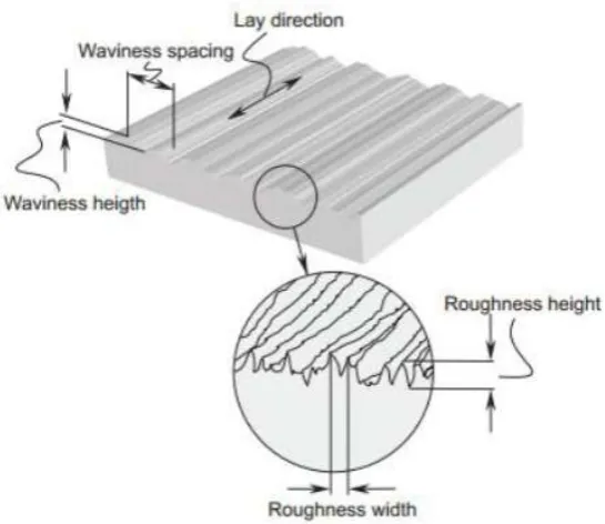
2.8 Factors influencing surface finish of turned metals 42
2.9 Chatter suppression in turning operation 50
2.10 Machining of composite 53
2.11 Factors influencing surface finish of turned composites 55
2.12 Chapter Summary 57
3 DYNAMIC MODEL OF TURNING OPERATION 59
3.1 Introduction 59
3.2 Development of mathematical formulation of Rotating Beam Subjected to Three Directional Moving Loads with Regenerative Chatter 60
3.2.1 Boundary Conditions 60
3.2.2 Energy method 63
3.2.3 Lagrange‟s equation 65
3.2.4 Three directional moving cutting forces with regenerative chatter mechanism 69
3.2.5 Improved dynamic model by adopting Insperger‟s cutting force model 73
3.2.6 Cutting Tool Equation of Motion 76
3.3 Elastic boundary condition 78
3.4 Methodology for Chatter Analysis / Numerical Integration methods in vibration analysis 84
3.4.1 Frequency Response Analysis 85
3.4.2 Transient Response Analysis 86
3.4.2.1 Runge-Kutta Method 87
3.4.2.2 Delay Differential Equations 89
3.5 Chapter Summary 91
4 EXPERIMENTAL MODAL ANALYSIS 93
4.1 Introduction 93
4.2 Basic components of experimental modal analysis (EMA) 97
4.2.1 Excitation of structure 98
4.2.2 Mechanism of sensing 100
4.2.3 Data acquisition and processing mechanism 101
4.3 Experimental modal analysis of metal and composite work piece 101
4.3.1 Free-free boundary 102
vii 4.4 Experimental modal analysis during machining of cylindrical
metal work piece at DUT 116
4.5 Chapter summary 120
5 NUMERICAL SIMULATION RESULTS 122
5.1 Overview 122
5.2 Parametric studies 123
5.2.1 Clamped pinned (metal work piece) 123
5.2.1.1 Convergence test 123
5.2.1.2 Effect of depth of cut 127
5.2.1.3 Effect of cutting speed 135
5.2.1.4 Effect of rotational speed 140
5.2.2 Elastic boundary (chuck pinned for metal work piece) 144
5.2.2.1 Introduction 144
5.2.2.2 Convergence test 144
5.2.2.3 Effect of depth of cut 147
5.2.2.4 Effect of cutting speed 155
5.2.2.5 Effect of rotational speed 159
5.2.3 Clamped pinned (composite work piece) 166
5.3 Vibration test during turning operation 168
5.4 Chapter summary 173
6 ANALYSIS AND DISCUSSION 175
6.1 Parametric Studies 175
6.1.1 Clamped pinned (metal work piece) 175
6.1.1.1 Effect of depth of cut 176
6.1.1.2 Effect of cutting speed 177
6.1.1.3 Effect of rotational speed 178
6.1.2 Elastic boundary (chuck pinned – metal work piece) 178
6.1.2.1 Effect of depth of cut 179
6.1.2.2 Effect of cutting speed 180
6.1.2.3 Effect of rotational speed 180
6.2 Validation between numerical and experimental results 181
7 CONCLUSIONS AND FUTURE WORKS 183
7.1 Summary of Findings of the Investigation 183
7.2 Contribution to New Knowledge 186
7.3 Recommendations for Further Investigation 187
7.4 List of Publications 188
REFERENCES 189
viii i. Appendix A1 - Calculation of deflection, v and w for
clamp-pinned boundary 207 ii. Appendix A2 - Derivation of Delay Differential equation for
clamp-pinned boundary 208 iii. Appendix A3 - Time delay function 211 iv. Appendix A4 - Determination of mode shape function for
clamp-pinned boundary 212 v. Appendix A5 - First derivation of mode shape function for
clamp-pinned boundary 213 vi. Appendix A6 - Second derivation of mode shape function for
clamp pinned boundary 214 vii. Appendix A7 - Calculation of cutting speed 215 viii. Appendix A8 - Calculation of deflection, v and w for elastic
Boundary 216 ix. Appendix A9 - Derivation of Delay Differential equation for
elastic boundary 219 x. Appendix A10 - Determination of mode shape function for
elastic boundary 221 xi. Appendix A11 - First derivation of mode shape function for
elastic boundary 222 xii. Appendix A12 - Second derivation of mode shape function for
ix
List of Figures
2.1 Conventional lathe machine at University of Liverpool... 13
2.2 Schematic illustration of a turning operation ... 15
2.3 (a) Chatter mark ... 18
2.3 (b) Chatter mark on turned work piece... 18
2.4 (a) Segmented chips ... 19
2.4 (b) Discontinuous chips ... 19
2.5 Regenerative chatter mechanism ... 24
2.6 Rotating shaft subjected to a moving load with three perpendicular forces ... 33
2.7 Torque and bending moment generated from Px and Pz force components translated to the neutral axis ...33
2.8 Elements of surface machine surface texture ... 43
3.1 Comparison between current dynamic model coordinate system and Insperger‟s coordinate system (a) current dynamic model coordinate system (b) Insperger‟s coordinate system …………....…... 74
3.2 Example of one value of 𝛽𝑛 showing the beam classical mode Shape ...81
3.3 Graph of new fitted theoretical (marked by red) and measured (marked by blue) mode shapes for the chuck-tailstock ... 84
4.1 Route to vibration analysis ... 95
4.2 General layout of EMA ...98
4.3 Impact Hammer ...100
x free-free boundary ………... 102 4.6 Apparatus used for modal testing (a) PCB impact hammer
(b) Kistler accelerometer (c) 12 channels LMS system ...103 4.7 A cylindrical metal work piece with its five measured locations ...103 4.8 The experimental mode shapes of the cylindrical metal work
piece for free-free boundary...106 4.9 The experimental mode shapes of the cylindrical composite work
piece for free-free boundary ……….…108
4.10 Modal test setup for cylindrical work piece in clamped-pinned
boundary condition ……….……..109
4.11 Kistler accelerometer and Micro-epsilon laser sensor ………….…….110 4.12 The experimental mode shapes of the cylindrical metal work
piece for clamp-pinned boundary ………...…112 4.13 Responses from laser sensor showing the noise ………...113 4.14 Modal test setup for clamped-pinned boundary in y and z
direction ...115 4.15 Schematic illustration of the vibration test set-up ………117 4.16 Two views of the experimental rig ………... 118 5.1 Dynamic response of deflection, v (y direction) with (a) one mode
(b) two modes (c) three modes (d) four modes (e) five modes. Note that the unit for x axis is time, t (s) and y axis is the dynamic
response, m... 125 5.2 Dynamic response of deflection, w (z direction) with (a) one mode
(b) two modes (c) three modes (d) four modes (e) five modes. Note that the unit for x axis is time, t (s) and y axis is the dynamic
response, m... 126
5.3 Dynamic response of deflection, v at different depths of cut with one mode (cutting speed = 0.2228 m/s, the rotational speed
= 1250 rev/min and the feed rate = 0.3 mm/rev)... 128 5.4 Dynamic response of deflection, w at different depths of cut with
one mode (cutting speed = 0.2228 m/s, the rotational speed
= 1250 rev/min and the feed rate = 0.3 mm/rev) ... 129 5.5 Dynamic response of deflection, v at different depths of cut with
xi 1250 rev/min and the feed rate = 0.3 mm/rev) ... 130 5.6 Dynamic response of deflection, w at different depths of cut with
two modes (cutting speed = 0.2228 m/s, the rotational speed =
1250 rev/min and the feed rate = 0.3 mm/rev) ... 131 5.7 Phenomenon of beats ...133 5.8 Dynamic response of deflection, v at different depths of cut with
three modes (cutting speed = 0.2228 m/s, the rotational speed =
1250 rev/min and the feed rate = 0.3 mm/rev) ... 133
5.9 Dynamic response of deflection, w at different depths of cut with three modes (cutting speed = 0.2228 m/s, the rotational speed =
1250 rev/min and the feed rate = 0.3 mm/rev)... 134 5.10 Dynamic response of deflection, v at different depths of cut with
four modes (cutting speed = 0.2228 m/s, the rotational speed =
1250 rev/min and the feed rate = 0.3 mm/rev)... 135 5.11 Dynamic response of deflection, w at different depths of cut with
four modes (cutting speed = 0.2228 m/s, the rotational speed =
1250 rev/min and the feed rate = 0.3 mm/rev) ... 136 5.12 Dynamic response of deflection, v at different cutting speeds with
one mode (depth of cut = 3.00 mm, rotational speed = 1250 rev/min and the feed rate = 0.3 mm/rev) ... 137 5.13 Dynamic response of deflection, w at different cutting speeds with
one mode (depth of cut = 3.00 mm, rotational speed = 1250 rev/min and the feed rate = 0.3 mm/rev) ... 138 5.14 Dynamic response of deflection, v at different cutting speeds with
two modes (depth of cut = 3.00 mm, rotational speed = 1250 rev/min and the feed rate = 0.3 mm/rev) ... 139
5.15 Dynamic response of deflection, w at different cutting speeds with two modes (depth of cut = 3.00 mm, rotational speed = 1250 rev/min
and the feed rate = 0.3 mm/rev) ... 139 5.16 Dynamic response of deflection, v at different cutting speeds with
three modes (depth of cut = 3.00 mm, rotational speed = 1250
rev/min and the feed rate = 0.3 mm/rev) ... 140 5.17 Dynamic response of deflection, w at different cutting speeds with
xii rev/min and the feed rate = 0.3 mm/rev) ... 140 5.18 Dynamic response of deflection, v at different cutting speeds with
four modes (depth of cut = 3.00 mm, rotational speed = 1250
rev/min and the feed rate = 0.3 mm/rev) ... 141 5.19 Dynamic response of deflection, w at different cutting speeds with
four modes (depth of cut = 3.00 mm, rotational speed = 1250
rev/min and the feed rate = 0.3 mm/rev) ... 142 5.20 Dynamic response of deflection, v at different rotational speeds
with one mode (depth of cut = 3.00 mm, cutting speed = 0.2228
m/s and the feed rate = 0.3 mm/rev) ... 143 5.21 Dynamic response of deflection, w at different rotational speeds
with one mode (depth of cut = 3 mm, cutting speed = 0.2228 m/s
and the feed rate = 0.3 mm/rev) ... 144 5.22 Dynamic response of deflection, v at different rotational speeds
with two modes (depth of cut = 3.00 mm, cutting speed = 0.2228
m/s and the feed rate = 0.3 mm/rev) ... 145 5.23 Dynamic response of deflection, w at different rotational speeds
with two modes (depth of cut = 3.00 mm, cutting speed = 0.2228
m/s and the feed rate = 0.3 mm/rev) ... 146 5.24 Dynamic response of deflection, v (y direction) with (a) one mode
(b) two modes (c) three modes (d) four modes (e) five modes. Note that the unit for x axis is time, t (s) and y axis is the dynamic
response, m ... 149 5.25 Dynamic response of deflection, w (z direction) with (a) one mode
(b) two modes (c) three modes (d) four modes (e) five modes. Note that the unit for x axis is time, t (s) and y axis is the dynamic
response, m ... 150 5.26 Dynamic response of deflection, v at different depths of cut with
one mode (1250 rev/min, cutting speed = 2.228m/s and feed rate is 0.3 mm/rev) ... 152 5.27 Dynamic response of deflection, w at different depths of cut with
xiii two modes (1250 rev/min, cutting speed = 2.228m/s and feed rate
is 0.3 mm/rev) ... 154 5.29 Dynamic response of deflection, w at different depths of cut with
two modes (1250 rev/min, cutting speed = 2.228m/s and feed
rate is 0.3 mm/rev) ...155 5.30 Dynamic response of deflection, v at different depths of cut with
three modes (1250 rev/min, cutting speed = 2.228m/s and feed rate is 0.3 mm/rev) ... 156
5.31 Dynamic response of deflection, w at different depths of cut with three modes (1250 rev/min, cutting speed = 2.228m/s and feed rate is 0.3 mm/rev) ... 157 5.32 Dynamic response of deflection, v at different depths of cut with
four modes (1250 rev/min, cutting speed = 2.228m/s and feed rate is 0.3 mm/rev) ... 158 5.33 Dynamic response of deflection, w at different depths of cut with
four modes (1250 rev/min, cutting speed = 2.228m/s and feed rate is 0.3 mm/rev) ... 159 5.34 Dynamic response of deflection, v at different cutting speed with
one mode (depth of cut = 3.00 mm, rotational speed = 1250 rev/min and feed rate is 0.3 mm/rev) ... 160 5.35 Dynamic response of deflection, w at different cutting speed with
one mode (depth of cut = 3.00 mm, rotational speed = 1250 rev/min and feed rate is 0.3 mm/rev) ... 161 5.36 Dynamic response of deflection, v at different cutting speed with
two modes (depth of cut = 3.00 mm, rotational speed = 1250 rev/min and feed rate is 0.3 mm/rev) ... 162
5.37 Dynamic response of deflection, w at different cutting speed with two modes (depth of cut = 3.00 mm, rotational speed = 1250 rev/min
and feed rate is 0.3 mm/rev) ... 162 5.38 Dynamic response of deflection, v at different cutting speed with
three modes (depth of cut = 3.00 mm, rotational speed = 1250
rev/min and feed rate is 0.3 mm/rev) ... 163 5.39 Dynamic response of deflection, w at different cutting speed with
xiv rev/min and feed rate is 0.3 mm/rev) ... 163 5.40 Dynamic response of deflection, v at different cutting speed with
four modes (depth of cut = 3.00 mm, rotational speed = 1250
rev/min and feed rate is 0.3 mm/rev) ... 164 5.41 Dynamic response of deflection, w at different cutting speed with
four modes (depth of cut = 3.00 mm, rotational speed = 1250
rev/min and feed rate is 0.3 mm/rev) ... 164 5.42 Dynamic response of deflection, v at different rotational speed
with one mode (depth of cut = 3.00 mm, cutting speed = 2.228 m/s and feed rate = 0.3 mm/rev) ... 165 5.43 Dynamic response of deflection, w at different rotational speed
with one mode (depth of cut = 3.00 mm, cutting speed = 2.228 m/s and feed rate = 0.3 mm/rev) ... 166 5.44 Dynamic response of deflection, v at different rotational speed
with two modes (depth of cut = 3.00 mm, cutting speed = 2.228 m/s and feed rate = 0.3 mm/rev) ... 167 5.45 Dynamic response of deflection, w at different rotational speed
with two modes (depth of cut = 3.00 mm, cutting speed = 2.228 m/s and feed rate = 0.3 mm/rev) ... 168 5.46 Dynamic response of deflection, v at different rotational speed
with three modes (depth of cut = 3.00 mm, cutting speed = 2.228 m/s and feed rate = 0.3 mm/rev) ... 169 5.47 Dynamic response of deflection, w at different rotational speed
with three modes (depth of cut = 3.00 mm, cutting speed = 2.228 m/s and feed rate = 0.3 mm/rev) ... 170 5.48 Dynamic response of deflection, v at different rotational speed
with four modes (depth of cut = 3.00 mm, cutting speed = 2.228 m/s and feed rate = 0.3 mm/rev) ... 171
5.49 Dynamic response of deflection, w at different rotational speed with four modes (depth of cut = 3.00 mm, cutting speed = 2.228 m/s and feed rate = 0.3 mm/rev) ... 172 5.50 Dynamic response of deflection, w at one mode (depth of cut =
0.25 mm, cutting speed = 0.2228 m/s, rotational speed = 1250
xv 5.51 Dynamic response of deflection, w at one mode (depth of cut =
0.25 mm, cutting speed = 0.2228 m/s, rotational speed = 1250
rev/min and feed rate = 0.3 mm/rev) ... 174 5.52 Dynamic response of deflection, v at one mode (depth of cut
= 3.0 mm, cutting speed = 0.2228 m/s, rotational speed =
1250 rev/min and feed rate = 0.3 mm/rev) ... 175 5.53 Dynamic response of deflection, w at one mode (depth of cut
= 3.0 mm, cutting speed = 0.2228 m/s, rotational speed =
1250 rev/min and feed rate = 0.3 mm/rev) ... 175 5.54 The being machined work piece of experiment 1 ………... 177 5.55 Deflections in time domain of experiment 1 ……….. 177 5.56 The being machined work piece ofexperiment 2shown chatter
xvi
List of Tables
2.1 Factors affecting surface roughness and their major investigators ... 47
2.2 Factors affecting surface roughness and major investigators ... 56
3.1 Possible boundary conditions... 61
3.2 Matching table for both coordinate systems ...74
3.3 Tabulated measured mode shapes, frequencies and 𝛽𝑛 ... 80
3.4 Example calculation for fitting the mode shape of 2Z ... 83
3.5 A technique of solving DDEs by reducing them to a sequence of ODEs ... 90
4.1 Nominal material properties of cylindrical metal work piece ...104
4.2 The three measured natural frequencies of the cylindical metal work piece ...104
4.3 Nominal material properties of cylindrical composite work piece ...106
4.4 The three measured natural frequencies of the cylindrical composite work piece ……….…107
4.5 The five measured clamped-pinned natural frequencies of the cylindrical metal work-piece ………....110
4.6 Properties of the cylindrical metal work piece used in the DUT test ...114
4.7 Free-free boundary condition for cylindrical metal work piece ……...114
4.8 Clamped-pinned boundary condition for metal work piece (y direction) ……….…..115
4.9 Clamped-pinned boundary condition for metal work piece (z direction) ……….……..116
xvii turning operation ……….…... 176
6.1 Comparison between theoretical and experimental of dynamic
xviii
List of Symbols
A Cross-sectional area (mm2) Bl(t) A time varying matrix cy Damping
d Work piece diameter in mm E Young‟s Modulus(kg/m3) f Feed rate (m/rev)
f (t) Driving force f. f. S Speed of the feed F(s) Laplace‟s Transform Ff Feed cutting force (N)
Ff (t) A time varying dynamic force due to cutting process
h Instantaneous depth of cut (mm) h(t) Instantaneous chip thickness
ho Intended cut (mm)
I Moment of inertia (kgm2) ky Stiffness of the cutting tool
Kx Cutting force coefficient (unitless)
Ky Cutting force coefficient (unitless)
Kz Cutting force coefficient (unitless)
l Length (mm)
my Mass
Mz Bending moment
xix Py Tangential force
Py(t) The magnitude of tangential cutting force
Pz Radial force
𝑞 𝑗 A generalized velocity
Q A generalize cutting force component
𝑄𝑗(𝑛) A non-conservative generalized force
s(t) Variable length from the spindle end to the location of the cutter s2X(s) Laplace‟s Transform of acceleration
t Time (s)
T Kinetic energy (J)
T Torque
v Deflection in z direction (mm) V Strain energy of the beam
V Cutting speed in m/min or ft/min w Deflection in y direction (mm) w Depth of cut in mm
W(x) A normal mode or characteristic function of the beam
y Displacement
y(t - ) Outside surface
y(t) Inside surface
Z Measured mode shape
αi(t) Corresponding modal coordinate
βi(t) Corresponding modal coordinate
δ Logarithmic decrement
ρ Mass density (GPa)
σ Root mean square
τ Time delay (s)
Shear plane angle
ω Angular rotation (rad/s)
n Theoretical frequency (Hz)
i(x) A spatial function that satisfies the boundary condition of the beam
xx
List of Abbreviations
1D One-dimensional
3D Three-dimensional
DD Dimensional deviations
DDEs Delay differential equations
DOF Degree of freedom
DUT Dalian University of Technology
EMA Experimental modal analysis
FFT Fast Fourier Transform
FRFs Frequency response functions
FRP Fibre reinforced polymer
GFRP Glass fibre reinforced polymer
IRFs Impulse response functions
MDOF Multiple degree of freedoms
ODEs Ordinary differential equations
SDOF Single degree of freedom
1
Chapter 1
Introduction
1.1
Introduction
This chapter contains a general introduction of the research (Section 1.1), motivations for the work (Section 1.2), research aim (Section 1.3) and scope of the thesis (Section 1.4). Section 1.5 describes the organisation of the thesis.
There are many different ways in which a product can be manufactured. Conventional techniques encompass processes such as machining, metal
forming, injection moulding, die casting, stamping and many others. Machining is one of the basic and most widely used operations necessary to cut things to
2 Therefore, this collection of processes is one of the most important among the basic manufacturing processes because of the value added to the final product.
In general, work pieces used in machining are made of metals due to their popular physical and mechanical properties in most engineering applications. In automotive industry for example, most of the parts are made from metals and their alloys. In cars, steel can crumple to absorb different impacts and hence are used to create the underlying chassis or cage beneath the
body that forms the skeleton of the vehicle, door beams, roofs, and other parts. A large number of manufacturers these days are gradually trying to substitute metals due to their shortcomings such as weight, and corrosion (for some metals) if not painted or coated. Plastic materials especially composites become prominent to avoid these drawbacks.
Over the years, manufacturers begin to explore other materials that cost less and perform better, being lighter, for instance or more corrosion resistant. Metals have been steadily incorporated with composite materials as they offer special advantages mentioned earlier. Although composite parts may be produced by other fabrication techniques like near net shape forming and modified casting, they still require further subsequent machining to facilitate precise dimensions to the part. Composites, unlike metals, are not isotropic and consist of both unique resins and fibres. Therefore machining composites in any post processing operation to get to the final part is indeed different.
Machining of composite has become an exciting subject in recent years since the use of composite materials has increased tremendously in various areas
in science and technology. With regard to the increase use of composites in many industries such as aerospace sector, the need to machine composite
3 and matrix properties, fibre orientation at the point of contact, and the relative volumes of fibre and matrix (Basavarajappa et al., 2006)
1.2
Motivations
One of the most-known machining processes is turning. Turning operation is one of the oldest and most versatile conventional ways to produce round parts by means of a single point cutting tool. Typical products made include parts as small as miniature screws for eyeglass frame hinges and as large as rolls for rolling mills, cylinders, gun barrels and turbine shafts for hydroelectric power plants. Normally turning is performed on a lathe machine where one end of the work piece is fixed to the spindle and the other end pin mounted to the tails stock. The tool is fed either linearly in the direction parallel or perpendicular to the axis of rotation of the work piece. The work piece will experience a rotary motion whereas the cutting tool will experience a linear translation.
Work piece and cutting tool come in contact with each other during turning operation. This dynamic interaction between a rotating work piece and moving cutting forces will suppress vibration and occasionally under certain
4 There are two groups of researchers who study on vibration and chatter noise in turning operation which are the structural dynamicists and manufacture engineers. The structural dynamicists studied on vibration of a shaft spinning about its longitudinal axis subjected to moving load (Ouyang, 2011). Vibration and chatter noise in turning operation is one example of the moving load problems as the cutter travels along the rotating work piece and this generate three directional moving cutting forces. The rotating work piece (usually treated as a beam or shaft) can be modelled in more than one beam theory. In general
there are four beam theories used which are Euler-Bernoulli, Rayleigh, shear and Timoshenko. The more sophisticated beam theories employed into the dynamic model of the turned work piece, the more accurate is the model. On the other hand, it is time consuming during computational work since sophisticated theories consider numerous interactions between several known variables. From the established dynamic model, vibration of the work piece during turning operation can be simulated.
The second group is from manufacturing engineers. Most of the manufacture engineers use simplified dynamic models for the work piece and do not treat it as well as structural dynamicists.The cutting tools often modelled as a lumped mass having one or two degrees of freedom (for describing motions of the cutting tool in the main cutting force direction). On the other hand, the manufacture engineer‟s cutting forces models are more realistic as they usually
model the cutting tool as a single degree of freedom (SDOF) or two degree of freedom (TDOF) with regenerative chatter mechanism. Mode coupling and regeneration of chatter are two common chatter mechanisms occur during machining. Moving cutting forces in turning operation depend on a number of
factors and regenerative chatter is the widely accepted mechanism which then introduces time delays in the established dynamic model. The length of this
delay in turning operation is the time period for one revolution of the work piece.
5 models developed in this study assumed a straightforward and common behaviour which captures some basic features of a turning operation in machining, in which a cutting tool is moved in the axial direction against a work piece that is rotating rapidly.This dynamic model should work well for both of the work piece, metal and composite. In the past, most studies of dynamic model of turning operation have generally assumed the work piece to be rigid and have, therefore, ignored work piece deformation.However, in practice, the work piece undergoes deformation as a result of an external force by the cutting tool. This
deformation affects and changes the chip thickness. In this thesis, the main contribution is to combine both dynamic models concept from those two groups; structural dynamicists and manufacturing engineers and develop a new mathematical model considering the work piece and cutting tools as a flexible work piece and flexible cutting tools. In addition the effect of the deflection-dependence of the moving cutting forces with regenerative chatter on the dynamic behaviour of the system at various travelling cutting speeds is also investigated.
1.3
Research Aim
The reliability of the developed dynamic model of turning operation is
6 work piece and the moving cutting forces, the produced data could not be used. Instead, a collaboration data from a collaborator in China had to be used. However, there has not been a reduced quality of the research. In addition, the dynamic model developed is originally aimed to be used for work pieces made from composite materials but since enough original work on metal work pieces has been done, the thesis is focused on metals. Composites are studied only during the preliminary stage of this research. Previous works on composites and their characteristics are also discussed in the literature review in the context of
vibration and chatter noise during turning of composite as they can be useful in future.
7
1.4
Scope of the thesis
The scope of the research covers several key areas which are given as
follows:
i. Identify the main factors that influence vibration and chatter noise
of turned metal and composite work pieces
One step towards a solution to the vibration and chatter noise problems is to investigate what kind of vibration that is present during turning operation. Thus, it is vital to investigate and identify several factors that will influence this vibration and chatter noise of turned metals and composites.
ii. Literatures review on dynamic model of turned metal with
regenerative chatter
The next scope is to provide a brief but comprehensive survey on the currently available dynamic models of turned metal and composite.
iii. Develop a dynamic model for the vibration of rotating Rayleigh
beam subjected to three directional moving cutting forces with
regenerative chatter and flexible cutting tool and code it in
MATLAB software
8 vibration of the cutter with regenerative chatter mechanism. It will involve great effort since the dynamic model for turning is very complicated in mathematics. Simulation is then needed to imitate the dynamic behaviour of the turning process subjected to moving cutting forces with regenerative chatter mechanism prior to actual machining and numerical examples are analysed accordingly.
iv. Numerical simulation of reducing vibration by parametric studies of
machining parameters
One has to predict and visualize the effect of several cutting and machine parameters to the turned metal parts so that a good finished product can be achieved. It is known that several machining parameters such as cutting speed, depth of cut, feed rate and rotational speed affect the surface finish of turned work piece. By means of the dynamic model established above, these machining parameters and work piece characteristics are simulated to observe how they influence surface finish and vibration of turned work piece. The effects of depth of cut, the rotational speed and cutting speed of the cutter on the vibration and chatter occurrence are examined. Unfortunately due to the lack of equipment, most of the work is done in the form of numerical simulation and the validation of the developed dynamic model is made by using and comparing the data from the collaborate group in China. Only modal testing of metal and composite work pieces has been conducted. Ideally, experiments will be performed to test the machinability of metal according to the recommended cutting and machining parameters and
9
1.5
Organization of the thesis
The thesis consists of seven chapters describing all the works done in the research. These chapters are structured as follows:
Chapter 1 described the introduction and background of the research. The motivation behind the research was also stressed out in this chapter. In addition, the aim of the research was also laid out. The scopes of the research as well were also highlighted as a framework of the research.
Chapter 2 presents a brief literature review on the background of metal cutting especially turning operation and machining of composite. The influence factors contributing to the surface finish of the turned metals and composites were also explained. The introduction to vibration and chatter noise in machining and what would contribute to the occurrence of chatter noise in turning of metals or composites are also presented. Two different mechanisms of chatter noise usually occurred in machining process were also discussed. The basic vibration/chatter theory of 1-2 degree of freedom (DOF) used by most manufacturing people is discussed. The classical beam theories used in this research were also explained. Lastly, the methods to suppress vibration and chatter noise in turning operation by means of active and passive controlled were also reviewed in this chapter.
Chapter 3 presents the theory and development details of dynamic model employed in turning operation. The classical beam theories used in this research were also explained. A number of regenerative chatter models developed were also presented. This chapter also introduces the dynamic models of a rotating shaft subjected to three directional moving cutting forces with regenerative chatter mechanism. The sequence of improved mathematical formulation developed was also presented and discussed.
10 work piece. Some cutting tests were also carried out on metals to identify the cutting force coefficient and cutting parameter effects.
Chapter 5 describes the numerical simulation works done and discuss the outcomes of the simulation which includes the parametric studies done to evaluate the effect of different cutting parameters on vibration.
Chapter 6 explained the detail analysis and discussion on the results from
the parametric studies. Explanation on how the dynamic model developed is validated is also stated.
11
Chapter 2
Literatures Review and Theory
The organisation of this literature review is as follows; Section 2.2 presents the fundamental knowledge of turning operation cutting parameters such as cutting speed, depth of cut and feed rate. Section 2.3 describes the vibration in turning operation and Section 2.4 explains the phenomena of chatter noise in turning operation. Two different chatter mechanisms are described and discussed. Section 2.5 discusses the mechanism of regenerative chatter and some of the equations involved. In the meantime, Section 2.6 introduces some fundamental concepts of moving load dynamics problem. A number of dynamic responses of a rotating shaft subjected to moving load are reviewed in Section 2.7 with references for readers to explore at their own time. Several factors that influence the vibration and surface finish of turned metal are discussed in section 2.8. In Section 2.9, machining of composite will be discussed briefly and some factors contributing to the vibration and surface finish of turned composites is explained in Section 10. Last but not least in section 2.11, various chatter suppression methods in turning operation are discussed. Lastly, section
12
2.1 Introduction
Most machining today is carried out to shape metals and alloys. Many
composites and plastic products are also machined. As regards to size, components from watch parts to aircraft wing parts are machined. In the engineering industry, the term machining is used to cover chip forming operations. Machining is an operation in which a thin layer of metal is removed by a wedge shaped tool from a larger body (Trent and Wright, 2000). It includes various processes in which a piece of raw material is cut into a desired final shape and size by a controlled material removal process. Machining also is one of the most widely used methods of producing the final shape of the manufactured products.
2.2 Turning Operation
There are three principals of machining process which are turning, drilling and milling. Other operations fall into miscellaneous categories such as shaping, planning, boring, broaching and sawing. The focus of this thesis is on turning operation. Turning operation is one of the oldest and most versatile conventional ways of producing parts that are basically in round shape. Turning means that the work piece is rotating while it is being machined. The starting material is usually a work piece that has been made by other processes such as casting, forging or extrusion.
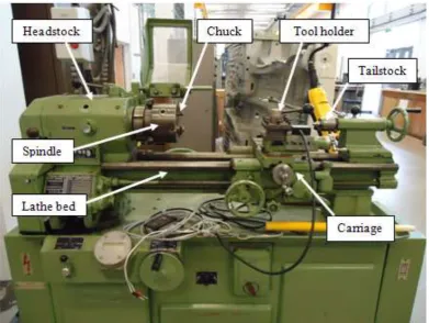
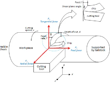
13 Figure 2.1: Conventional lathe machine at University of Liverpool
On a lathe, the tool is held rigidly in a tool post and moved at a constant rate along the axis of the work piece, cutting away a layer of metal to form a cylinder as shown in Figure 2.2. The tool is fed either linearly in the direction parallel or perpendicular to the axis of rotation of the work piece. The work piece will experience a rotary motion whereas the cutting tool will experience a linear translation. The three components of the cutting force acting on the rake face of the tool are also depicted in Figure 2.2. Normal to the cutting edge is called the tangential force, Py. This usually is the largest of the three components
and acts in the direction of cutting velocity. The force component acting on the tool, parallel with the direction of feed, is referred to as feed force, Px. This force
acts in the normal direction to the main cutting forces Py. The third component,
Pz , tend to push the tool away from the work in the radial direction, is the
smallest of the force components in simple turning operation.
14 knowledge of the variable factors of cutting speeds, feed rate and depth of cut must be understood (Trent and Wright, 2000) and below are the definitions for each of the turning process parameters.
The cutting speed (V) is the rate at which the uncut surface of the work passes the cutting edge of the tool, usually expressed in units of m/minor ft/min. The cutting speed of a tool is the speed at which the metal is removed by the tool from the work piece. Cutting speed is usually between 3 and 200 m/min(10
and 600 ft/min) (Trent and Wright, 2000). The cutting speed can be calculated using the equation 2.1 below:
𝑉 =
𝑁 1000 𝑑(2.1)
where V is the cutting speed (m/min), N is the spindle speed (rev/min) and d is the work piece diameter. Since 𝜋𝑑 is constant, thus the cutting speed depends on the spindle speed in which it is usually being determined first before actual turning operation according to Trent and Wright (2000).
The feed rate (f) is the distance moved by the tool in an axial direction at each revolution of the work piece. The feed rate may be as low as 0.0125 mm (0.0005 in) per revolution and with very heavy cutting, it can go up to 2.5 mm (0.1 in) per revolution as mentioned by Trent and Wright (2000). Equation 2.2 is
normally used to calculate the feed rate;
𝐹𝑒𝑒𝑑 𝑅𝑎𝑡𝑒 = 𝑓𝑒𝑒𝑑 x 𝑁
(2.2)where N is the spindle speed (rev/min), feed is in mm/rev and the unit of feed rate is in mm/min.
15 depth of cut may vary from zero to over 25 mm (1 in). Equation 2.3 is sometimes used to define a depth of cut;
𝐷𝑒𝑝𝑡ℎ 𝑜𝑓 𝑐𝑢𝑡 =
𝑑1−𝑑22
(2.3)
where 𝑑1 is diameter of the work surface before cutting and 𝑑2 is the diameter of the machined surface. The unit of a depth of cut is in mm.
The rotational speed () or sometimes called speed of revolution is the
number of complete rotations, revolutions, cycles, or turns per time unit. It is a cyclic frequency, measured in radians per second or in hertz or in revolutions per minute (rev/min or min-1) or revolutions per second in everyday life. Equation 2.4 is used to define a rotational speed;
𝜔 = 𝑣
𝑟 (2.4)
[image:37.595.142.515.442.731.2]where v is a tangential speed and r is a radial distance.
16
2.3
Vibration in
Machining
Vibrations in machining are complex phenomena. During machining,
work pieces are being cut and remove in discrete chunks. Each time the cutting tool takes a bite, it exerts a force on the work piece that was not there an instant ago. The work piece responds to this force by deflecting or by molecules compressing closer together, and generate mechanical stress. This mechanical stress travels through the work piece as a whole and the work piece acts like a spring to deflect and then return into shape. This explains vibration phenomenon during machining process.
Vibration is defined as any motion that repeats itself after interval of time and can be classified in several ways (Rao, 1995). There are two type of vibrations occurred during machining; forced and self-excited vibration. Forced vibration is generally caused by some periodic applied force present in the machine tool, such as that from gear drives, imbalance of the machine tool components, misalignment, and motors and pumps (Altintas, 2000). The basic solution to forced vibration is to isolate or remove the forcing element. If the forcing frequency is at or near the natural frequency of a component of a machine tool system, one of the frequencies may be raised or lowered. The amplitude of vibration can be reduced by increasing the stiffness or by
employing a damping system.
17 unwanted noise. This unwanted noise is known in machining world as chatter
noise.
2.4
Chatter Noise in Turning Operation
Chatter noise in machining is complex phenomena too similar to the vibration in machining. Chatter is an abnormal tool behaviour which it is one of the most critical problems in machining process and must be avoided to improve the dimensional accuracy and surface quality of the product. Chatter is a harmonic imbalance that occurs between the tool and the work piece because they are bouncing against each other. Chatter can be caused by the tool bouncing in or out of the work piece or the work piece bouncing against the tool, or both. It is not always easy to determine why chatter is happening.
Chatter needs to be taken into account during machining as it causes serious problems in machining instability. One of the most detrimental
18 Figure 2.3 (a): Chatter mark (Budak and Wiercigroch, 2001)
Figure 2.3 (b): Chatter mark on turned work piece (Tlusty, 2000)
19 Figure 2.4 (a): Segmented chips (Tlusty, 2000)
Figure 2.4 (b): Discontinuous chips (Birhan, 2008)
Machine tool chatter has long been studied as interesting phenomenon. Chatter is self excited vibration that occurs in metal cutting if the chip width is too large with respect to the dynamic stiffness of the system (Altintas, 2000). Meanwhile, dynamic stiffness is defined as the ratio of the amplitude of the force applied to the amplitude of the vibration (Rao, 1995). A machine tool has different stiffness values at different frequencies and changing cutting parameters can affect chatter. Under such conditions the vibration starts and quickly grows. The cutting force becomes periodically variable, reaching
20 increasing, the machine tool system becomes unstable. The machined surface becomes undulated, and the chip thickness varies in the extreme so much that it becomes dissected. In general, self excited vibrations can be controlled by increasing the dynamic stiffness of the system and damping (Birhan, 2008). Almost 100 years ago, Taylor (1907) described machine tool chatter or chatter as the most obscure and delicate of all problems faced by the machinist. Chatter significantly affects work piece surface finish, dimensional accuracy, and cutting tool life (Stephenson and Agapiou, 1996). In an attempt to achieve high
material removal rates, aggressive cutting strategy is often employed in industry. This practice may cause chatter to occur more often in a competitive production environment, and makes chatter research imperative.
Such phenomena of chatter occurs during machining is due to material removal process in turning operation, both cutting tool and work piece are in contact with each other. Vibration and chatter noise are suppressed under certain conditions by this dynamic interaction between a rotating work piece and moving cutting forces from the tool. The cutting tool is subjected to a dynamic excitation due to the deformation of the work piece during cutting. The relative dynamic motion between the cutting tool and the work piece produce vibration and chatter thus affect the surface finish. Poor surface finish and dimensional accuracy of the work piece, possible damage to the cutting tool and irritating noise from excessive vibration are the results of uncontrolled vibration and chatter. Thus vibration related problems are of great interest in turning operations.
Furthermore, machine tool chatter is thought to occur for a variety of
reasons. Mode coupling and regenerative chatter are two basic mechanisms that cause machine tool chatter and will be explained in the following sections.
21 Another factor that should be considered in machining is machine stiffness. Machine stiffness is recognized as one of the important parameter during machining since low machine stiffness affects the magnitude of vibration during machining (milling, turning, drilling etc). It can have adverse effects on product surface finish where surface finish is directly affected by a dynamic displacement (vibration) between cutting tool and work piece according to Rao, (1995).
2.4.1
Mode Coupling
Mode coupling is recognized as one of the causes of chatter which is often called primary chatter. Mode coupling is a mechanism of self excitation that can only be associated with situations where the relative vibration between the tool and the work piece can exist simultaneously in at least two directions in the plane of the cut. Usually mode coupling occurs without any interaction
between the vibration of the system and undulated surface of work piece. It acts only within vibratory systems with at least two degrees of freedom, which is due to the fact that the system mass vibrates simultaneously in the directions of the degrees of freedom of the system, with different amplitudes and phase.
Mode coupling is very complex and is inherently related to the dynamics of the cutting process. It may arise from different physical causes such as the dynamical effects of the geometry of the cutting tool on the cutting process. According to Huang and Wang (2009), the rotation direction of chatter vibration is an important feature to determine whether mode coupling chatter occurs or not.
2.4.2
Regenerative Chatter
22 the work piece or by the oscillating cutter running over the wavy surface produced from the previous cut. It occurs whenever cuts overlap and the cut produced at time leaves small waves in the material that are regenerated with
each subsequent pass of the tool on the previous cut surface (Kashyzadeh and Ostad-Ahmad-Ghorabi, 2012).
The tool in the next pass encounters a wavy surface and removes a chip periodically. The chip thickness produced varies after each successive cut.This will produce vibration and depending on conditions derived further on, these vibrations may be at least as large as in the preceding pass. Thus, the cutting force, which is a function of the chip thickness, depends not only on the current position of the tool and work piece but also on the delayed value of the work piece displacement. The newly created surface is again wavy in this way the waviness is continually regenerated.
Regenerative chatter is considered to be the dominant mechanism of
chatter in turning operations. If regenerative tool vibrations become large enough that the tool looses contact with the work piece, then a type of chatter
known as multiple regenerative chatter occurs. This mechanism has been the subject of study by Shi and Tobias (1984).
23 Several theories have been proposed to explain the occurrence of chatter instability for optimizing certain combination of process parameters such as feed rate, depth of cut, rotational speed, variation of chip thickness and variation of cutting force. In the work by Tobias and Fishwick (1958), the dynamics of the cutting process were modelled and effects such as process damping were included in their stability model. Tlusty and Polacek (1963) created a stability condition in which stability limits can be calculated based upon the system dynamics for orthogonal machining. Several dynamic models for regenerative
chatter have been put forward, for example in the studies of Altintas (2000) and Tlusty (2000). Early stability lobe diagrams were created by Merrit (1965) based upon feedback control theory to model regenerative chatter. These early studies provided insight into the elementary chatter mechanisms.
In the past, by choosing the appropriate combination of cutting parameters for example, the feed rate, depth of cut, rotational speed, different chip thickness and variation of cutting force to prevent the occurrence of chatter during turning operation.
2.5
Regenerative Chatter Mechanism in Turning
Operation
Regenerative chatter is a principal mechanism of chatter in turning operations. Tobias (1965) developed a regenerative machine tool chatter theory where the cutting force is considered to be a function of both the current and previous cuts. The theory is widely accepted as the most appropriate to describe the regenerative type chattering phenomenon, and it has become a foundation of many theoretical and experimental researches regarding cutting processes.
In this section the underlying mechanism of regenerative chatter in turning operation is explained. This regenerative chatter mechanism has been the subject of studies by Tobias (1965), Shi and Tobias (1984), and Stepan and
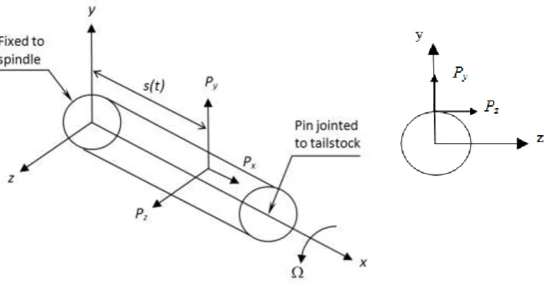
24 are among the first to study regenerative chatter in turning operation. Figure 2.5 can be used to illustrate one degree of freedom of regenerative chatter in turning operation.
The work piece is supported at one end by chuck and the other end by tailstock on lathe machine. The chuck is often represented with linear spring. During turning process, the work piece will rotate as it is being machined. The cutting tool movement is parallel to the longitudinal axes of the work piece and
[image:46.595.146.508.386.724.2]depending on the depth of cut. When the cutting tool makes contact with the work piece, it will deflect. As the cutting tool moves along its direction, there will be a variation in the magnitude and the direction of cutting forces because the previous cut leaves a wavy surface finish due to structural vibrations. The developing vibrations will lead to the increase of cutting force thus, resulting poor surface finish (Altintas, 2000).
Figure 2.5: Regenerative chatter mechanism (Altintas, 2000)
P
y(t) = K
yf
qy
25 The work piece is free to move in the feed direction and the feed cutting force, Py applied causes the work piece to vibrate. Presume a single point cutter
is fed perpendicular to the axis of cylindrical shaft. During the first revolution, the surface of the work piece is smooth which is without waves but due to the bending vibration of the work piece it will initially leave a wavy surface in the feed cutting force, Py direction. As a second revolution takes place, the previous
surface now has two waves at the inside and outside surface of the work piece. The inside surface denoted as y(t) is originated from the cut made by the tool whereas the outside surface indicated by 𝑦(𝑡 − 𝜏) is the effect of the vibrations during the previous revolution of cutting. The wavy surface leads to variable chip thickness, cutting force and vibration. This regeneration of chatter mechanism can be represented in the mathematical form below;
ℎ 𝑡 = ℎ𝑜− 𝑦 𝑡 − 𝑦 𝑡 − (2.5)
where h(t) is instantaneous chip thickness, ho is the intended cut, 𝑦 𝑡 − 𝑦 𝑡 − is the dynamic of chip thickness and is a rotation speed of the shaft
(rev/s). The associated time delay is the time period of one revolution of the
work piece
𝜏 =
2 𝜋 𝜔(2.6)
By assuming the work piece is a one single degree of freedom in the radial direction which consists of mass and spring system, the corresponding equation of motion can be written as below;
𝑚𝑦𝑦 𝑡 + 𝑐𝑦𝑦 𝑡 + 𝑘𝑦𝑦 𝑡 = 𝐹𝑓(𝑡) (2.7)
The magnitude of tangential cutting force Py(t) is proportional to the
instantaneous chip thickness h(t).
26 where Ky is the cutting force coefficient, f is feed rate (m/rev) and qy is the
exponents determined from Han et al. (2010) and h is the instantaneous depth of cut. This tangential cutting force not only depends upon the present cut y(t), but also on a delayed value of displacement of the previous cut of the tool 𝑦(𝑡 − 𝜏).
2.5.1 Chatter Modelling Theory
To set up a system of dynamic equations for studying chatter onset conditions, a reliable cutting force model, a mechanistic chatter model, and an accurate work piece deformation model are required. Depending on the relative flexibility of the work piece and the cutting tool, different chatter models may be developed. If the flexibility of the tool structure is predominant, the work piece may be considered rigid. Rigid is meant by the work piece is properly tightened at the chuck and deflection is assumed to be zero for simplification of the results. Flexible tool is defined as the ability to deflect in the main cutting force direction or in both directions. This happen due to the tool shank is only tighten by screw at the tool post (deflection is inevitable).
A large body of work has been published in chatter modelling over the last fifty years. Traditional models of the turning process consider a rigid work
piece and vibration of the machine tool structure are studied by a few early researcher such as Tobias and Fischwick (1948), Nathan (1959), Merrit (1965), and Marui (1983). Numerous researchers investigated single degree of freedom regenerative tool models such as Tobias (1965), Hanna and Tobias (1974), Shi and Tobias (1984), Fofana (1993), Johnson (1996), Nayfeh et al. (1998), Kalmar-Nagy et al. (2001), Stepan (2001), Kalmar-Nagy (2002), Stone and Campbell (2002) and Stepan et al. (2003).
27 directions working over rigid work piece. These chatter models developed on the basis of rigid work piece assumption are generally valid for cutting tools having a long tool shank in turning operations.
Chiou and Liang (1997) established a dynamic turning model for cutting rigid work piece with a flexible cutting tool. A comprehensive expression of the equation of motion for the dynamic cutting system incorporating the effects of cutting and contact forces is established. Machining experiments were
conducted on a conventional lathe with the use of a specially designed flexible tool which can only vibrate parallel to the feed and perpendicular to the cutting velocity direction. The work piece is cut so as to observe the mechanism of the cutting tool chatter stability corresponding to the continuous variation of width of cut and cutting speed. The chatter stability was observed in verification of the analytical solutions over a range of cutting velocities and width of cuts. Among these cutting conditions, flank wear has been shown to have a significant effect on the chatter stability.
The simplest model that models the tool as a one degree of freedom is underdamped linear oscillator excited by the variation in undeformed chip thickness from one revolution to another (Tobias and Fishwick, 1948). The vast majority of these investigations employ a single degree of freedom (SDOF), representing the lumped mass behaviour of the cutting tool at the cutting zone. Equation (2.9) describes the motion during cutting for a SDOF cutting tool and a rigid work piece, given as
𝑚𝑦𝑦 𝑡 + 𝑐𝑦𝑦 𝑡 + 𝑘𝑦𝑦 𝑡 = 𝐹𝑓 𝑡 (2.9)
where y is the displacement, Ff (t) is a time varying dynamic force due to cutting
process, my is the mass, cy is the damping and ky is the stiffness of the cutting
tool. Typically, the work piece is assumed to be rigid and the cutting tool to be vibrates.
28 the tool will exert force on the work piece, there will be wok piece deflection and the chip thickness will be changed. In addition, most of the work pieces used are long and slender having a smaller ratio of diameter over length, d/l (ratio is equal to less than 1). Due to this, deflection is likely to occur during cutting even though one side of the end is supported by tailstock as weight factor contributes to the deflection.
Chen and Tsao (2006) considered flexible work piece in his model and
discussed a stability analysis of regenerative chatter for turning a cantilever beam. In the past studies, the work piece was assumed to be rigid, and only the tool vibration was considered. The research is focus on the regenerative chatter
where a flexible work piece is considered rather than a rigid assumption. Such flexibility will affect the cutting force due to work piece deflection and will result in a smaller real chip thickness and larger critical chip width. Two models are used for the work piece and the tool, which correspond to a second order
partial differential equation and a second order ordinary differential equation,
respectively. The interaction between the work piece and the tool can be
discussed and analysed based on these models. The effect of the critical chip
width under different spindle speed is also discussed. By considering the
deformation of the work piece under different conditions, the results show that
the critical chip width of the deformed case is always larger than the rigid body
case. Under the same natural frequency, both the work piece deflection and the critical chip width will become larger. Under the same work piece deflection, the smaller the natural frequency, the larger the critical chip width
Chen and Tsao (2006) as well presented a dynamic model of cutting tool
with and without tailstock supported work piece using beam theory. Here, the
effects of work piece parameters are studied on the dynamic stability of turning
process by treating the work piece as a continuous system. In contrast to the
29 second order partial differential equation and a second order ordinary differential equation, respectively. The developed models permit a full analysis and discussion of the interaction between the work piece and the tool. The results have shown that the deflection of the work piece affects the cutting force. It has also been shown that the larger the work piece deflection, the larger the critical chip width. In addition for a constant work piece deflection, the smaller the natural frequency, the larger the critical chip width. When the slenderness ratio of the work piece and the spindle speed are not excessive, work piece
deformation considerations can be ignored without affecting the stability analysis significantly. However, the smaller slenderness ratio of work pieces and higher spindle speeds associated with many modern precision machining processes lead to significant deformation of the work piece. Hence, the stability analysis of turning processes should take deformation effects into consideration. Studies of chatter based on the rigid tool assumption and the flexible work piece modelled as the Euler–Bernoulli beams include those of Lu and Klamecki (1990), Kato and Marui (1974), Jen and Magrab (1996), and Shawky and Elbestawi (1998).
Moreover, a two-degree of freedom (TDOF) is defined by a system that
requires two independent coordinates to describe their motion. In chatter model,
the tool and work piece are modelled as two separate single degree of freedom spring mass damper systems. They are generally in the form of coupled differential equations that is each equation involves all the coordinates. If a harmonic solution is assumed for each coordinate, the equations of motion lead to a frequency equation that gives two natural frequencies of the system. If suitable initial excitation is applied, the system vibrates at one of these natural
frequencies. During free vibration at one of the natural frequencies, the amplitudes of the two degrees of freedom (coordinates) are related in a specified
30 represent the dynamics of chatter. Chandiramani and Pothala (2006) depicted dynamics of chatter with two degrees of freedom model of cutting tool.
Sekar et al. (2009) proposed an analytical scheme for stability analysis in
turning process by considering the motion of tailstock supported work piece
using a compliance model of tool and work. A dynamic cutting force model
based on relative motion between the cutting tool and work piece is developed
to study the chatter stability. Linear stability analysis is carried out in the
frequency domain and the stability charts are obtained with and without
considering work piece flexibility. The research proposed a compliant two
degrees of freedom dynamic cutting force model by considering the relative
motion of work piece with cutting tool. Tool and work piece were modelled as
two separate single degree of freedom spring-mass-damper systems. The model
allows selection of different operating conditions with and without a tailstock
support by accounting the fundamental natural frequency of the work piece.
Effect of cutting position, work piece dimensions, cutter flexibility, and cutter
damping on the dynamic stability have been presented with the proposed
dynamic model.
Dassanayake (2008) investigated different stages of stability of the work piece and tool by simulating three dimensional (3D) models of work piece cutter deflections in response to a nonlinear regenerative force with a method of rotor dynamics. Tool chatter in turning process is addressed with a new perspective. Turning dynamics is investigated using a 3D model that allows for simultaneous work piece tool deflections in response to the exertion of nonlinear regenerative force. The work piece is modelled as a system of three rotors, namely,
unmachined, being machined and machined, connected by a flexible shaft. Such a configuration enables the work piece motion relative to the tool and tool


![Methyl 6 oxo 4 phenyl 2 [(Z) 2 (pyridin 2 yl)ethenyl] 1,4,5,6 tetrahydropyridine 3 carboxylate](data:image/gif;base64,R0lGODlhAQABAIAAAP///wAAACH5BAEAAAAALAAAAAABAAEAAAICRAEAOw==)