This is a repository copy of Integrating Dynamics and Wear Modelling to Predict Railway
Wheel Profile Evolution.
White Rose Research Online URL for this paper:
http://eprints.whiterose.ac.uk/880/
Book Section:
Lewis, R., Braghin, F., Ward, A. et al. (4 more authors) (2003) Integrating Dynamics and
Wear Modelling to Predict Railway Wheel Profile Evolution. In: Ekberg, A., Kabo, E. and
Ringsberg, J., (eds.) 6th International Conference on Contact Mechanics and Wear of
Rail/Wheel Systems : CM2003. CHARMEC , Gothenburg , pp. 7-16. ISBN 9163139286
[email protected] https://eprints.whiterose.ac.uk/
Reuse
Unless indicated otherwise, fulltext items are protected by copyright with all rights reserved. The copyright exception in section 29 of the Copyright, Designs and Patents Act 1988 allows the making of a single copy solely for the purpose of non-commercial research or private study within the limits of fair dealing. The publisher or other rights-holder may allow further reproduction and re-use of this version - refer to the White Rose Research Online record for this item. Where records identify the publisher as the copyright holder, users can verify any specific terms of use on the publisher’s website.
Takedown
If you consider content in White Rose Research Online to be in breach of UK law, please notify us by
6th International Conference on Contact Mechanics and Wear of Rail/Wheel Systems (CM2003) in Gothenburg, Sweden June 10–13, 2003
INTEGRATING DYNAMICS AND WEAR MODELLING TO
PREDICT RAILWAY WHEEL PROFILE EVOLUTION
R Lewis1, F. Braghin2, A.Ward1, S. Bruni2, R.S. Dwyer-Joyce1, K. Bel Knani3 and P. Bologna3 1The University of Sheffield,
Dept. of Mech. Eng., Mappin Street, Sheffield, S1 3JD,
UK
2Dept. of Mech. Eng., Politecnico di Milano,
Via La Masa 34, 20158, Milano,
ITALY
3Fiat Research Centre, Strada Torino 50, 10043, Orbassano (TO),
ITALY
[email protected], [email protected]
Abstract
The aim of the work described was to predict wheel profile evolution by integrating multi-body dynamics simulations of a wheelset with a wear model.
The wear modelling approach is based on a wear index commonly used in rail wear predictions. This assumes wear is proportional to Tγ, where T is tractive
force and γ is slip at the wheel/rail interface. Twin disc testing of rail and wheel materials was carried out to generate wear coefficients for use in the model.
The modelling code is interfaced with
ADAMS/Rail, which produces multi-body dynamics simulations of a railway wheelset and contact conditions at the wheel/rail interface. Simplified theory of rolling contact is used to discretise the contact patches produced by ADAMS/Rail and calculate traction and slip within each.
The wear model combines the simplified theory of rolling contact, ADAMS/Rail output and the wear coefficients to predict the wear and hence the change of wheel profile for given track layouts.
INTRODUCTION
New specifications are being imposed on railway wheel wear and reliability to increase the time between wheel reprofiling operations, improve safety and reduce total wheelset lifecycle costs. In parallel with these
requirements, railway vehicle missions are changing due to: the need to operate rolling stock on track with low radius curves as well as the high radius curves on high speed lines; increasing speeds and the decrease of track quality due to a reduction in maintenance.
These are leading to an increase in the severity of the wheel/rail contact conditions [1] which will increase
the likelihood of wear occurring. Excessive wear can affect the dynamic behaviour of the railway vehicle and reduce ride comfort; impact upon the potential for derailment and reduce the integrity of the wheel material [2].
In order to deal with these demands new design methodologies are required that integrate advanced numerical tools for modelling of railway vehicle dynamics and suitable models to predict damage sustained by wheels under typical operating conditions.
The aim of the work described was to develop such a procedure, integrating multi-body dynamics simulations of a railway wheelset with a wear model to predict wheel profile evolution. This will help in scheduling wheel maintenance and regrinding; optimising railway vehicle suspensions and wheel profiles and in evaluating new wheel materials.
The main drawback in existing analysis tools, that incorporate dynamic and wear modelling for predicting the evolution of wheel profiles [3, 4, 5], is in the
approach to wear modelling used in each. Previously developed wear models are taken and used with wear coefficients taken from the literature. No proper investigations have been conducted to investigate the wheel material wear mechanisms or regimes and validate the wear models being used. The aims in this work were therefore to assess wear modelling approaches used for wheel/rail wear prediction and select the most appropriate for this application and to fully investigate the wear properties of the wheel material and generate suitable data to use in the wear model developed.
This work was carried out as part of the European Community funded project HIPERWheel. One of the aspects of this project was to develop an integrated CAE procedure for assessing wheelset durability taking into account damage mechanisms such as metal fatigue, rolling contact fatigue, wear and fretting.
BACKGROUND
Wheel Motion on a Rail
The dynamic behaviour of a rail vehicle running in tangent track or curve is strictly related to wear phenomena occurring on wheel profiles. In fact, wheel
wear occurs as a consequence of the contact conditions (contact forces and slips) induced by the wheelset service. Conversely, the modification of wheel surfaces produced by wear has a large impact on vehicle performances and running behaviour.
Two main wear effects are commonly present in railway wheels: a change in the transversal profile, sometimes called regular wear, and the formation of
periodic wear patterns in circumferential direction, called wheel out-of-roundness or irregular wear.
Regular wear, upon which this work focuses, is
produced by slowly varying values of contact forces and slips associated with the longitudinal and lateral motion of the wheelset on the track.
Particularly relevant to the formation of regular wear is the wheel motion during curve negotiation. The wheelset experiences a lateral motion with respect to the rail, together with a yaw rotation which leads to the formation of an angle of attack between the local radial
direction of the curve and wheelset axle. The lateral wheel motion leads to a change in the position of wheel-rail contact patch along the profiles and to a variation of the rolling radius; whilst, the presence of a non-zero angle of attack produces a lateral creepage component.
As a consequence of this rather complex wheel-rail contact regime, two distinct wear regions appear on the wheel profile: one on the flange and the other the tread. Flange wear typically takes place for each bogie on the outer wheel of the leading axle, which is
subjected to a high flange force under large longitudinal and lateral creepages, while tread wear occurs on the inner wheel due to creep forces [6]. Wear rates in these
two regions depend on a large variety of parameters including vehicle type (dimensions, axle loads, vehicle suspensions), vehicle mission profile (service speed, geometry of the line) and the wheel and rail materials.
Appropriate models of the wear phenomena and their interaction with vehicle dynamics are therefore needed in order to optimise wheelset resistance to wear and to minimise total life cycle costs.
Mathematical Modelling of Wheel/Rail
Contact
In order to investigate wear effects at wheel/rail interface, it is necessary to reproduce the variable position of the contact patch along the profiles, together with the values of longitudinal and lateral creepages and the corresponding contact force components. The mathematical description of these phenomena is further complicated by the fact that all contact parameters strongly depend on the geometry of wheel and rail profiles, and that, under some circumstances, multiple contacts can take place between the same wheel/rail pair.
The study of wheel/rail contact can be divided into a normal problem, involving the computation of the
number, position and size of wheel/rail contact patches together with the distribution of normal pressures inside the contact, and a tangential problem, consisting of the
calculation of the tangential stresses in each contact patch [7]. Owing to the quasi-identity assumption, these
two problems are assumed to be decoupled and solved separately.
Available methods for solving the normal problem range from the analytical solution by Hertz to the numerical procedure implemented in the CONTACT software [7]. This latter method requires a very high
computational effort, and therefore is not well suited for repeated applications as is required in the simulation of wear formation processes. A reasonable compromise is represented by approximate numerical techniques, like the method of rigid interpenetration [8] or by a
multi-elliptic approximation [9]. Several different approaches
are available also to solve the tangential problem. Nevertheless, a reasonable compromise between accuracy and numerical efficiency can be achieved using the FASTSIM procedure [10].
The CONTACT algorithm has been used in the past with the output of vehicle dynamics simulations to predict wear and good qualitative agreement noted [11].
In the work described here, the procedure is improved by incorporating a faster contact simulation and an improved wear process.
Wheel Wear Phenomena
As mentioned above, wheel wear is related to conditions of force and slip in the wheel/rail contact. Two wear regimes for wheel materials have been defined [12],
mild (low force, low slip) and severe (high force, high
slip). The regimes were described in terms of wear mechanism as well as wear rate.
At the very lowest conditions of contact stress and slip typical of those seen in a tread contact (mild regime), a nearly continuous oxide film was observed on the material surfaces. As contact conditions became more arduous (towards those experienced in a flange contact) in severe wear, the material exhibited partially oxidised surfaces together with metal flakes. The oxide particles were less than 2µm across while the metal flakes were 100-200µm across. These elongated metal flakes resulted from cracks running back from the surface following the flow lines of the deformed material. The severe wear mode generated wear debris consisting only of metal flakes up to 50µm thick.
Wheel Wear Modelling Approaches
Most wear indices developed for predicting wear of rails/wheels [13, 14, 15, 16, 17] are either linear or
was apparent in tests run with an attack angle of zero [18].
A wear index approach has been proposed for predicting wear of rails that adopts an energy approach in the analysis of the relationship between wear rate and contact conditions [19]. It is assumed that wear rate
(µg/m rolled/mm2 contact area) is related to work done at the wheel/rail contact (wear rate = KTγ/Α, where T is
tractive force and γ is slip at the wheel/rail interface, K
is a wear coefficient and A is the contact area). Various
researchers have reported wheel/rail wear results using twin disc test machines of varying geometries as well as full scale test results that support this approach [12, 18, 20, 21, 22]. This approach, however, has limitations. It
was found to break down at high slip and contact stress conditions [12].
The most suitable basis for a wear model was clearly the wear index based on the proportionality of wear with work done at the wheel/rail contact. It was apparent, however, that improvements could be made to this modelling approach, especially with regard to the wear regime at higher slips and contact stresses. Tread and flange wear fall with different wear regimes and it may therefore be better to use different wear constants for each. An improved definition of the wear regimes was also required.
WEAR TESTING
In order to characterise the wear of the wheel material, wear tests were carried out using a twin disc test machine. These were designed to establish mechanisms, identify wear regimes of the wheel material and determine constants necessary for the wear index analysis to be carried out in the modelling procedure described later.
Apparatus
A twin disc test machine was used to carry out the testing (shown in figure 1). The original development of
this machine and more recent work carried out to add a computer control system have been described
previously [23, 24].
The test discs are hydraulically loaded together and driven at controlled rotational speed by independent electric motors. Shaft encoders monitor the speeds continuously. A torque transducer is assembled on one of the drive shafts and a load cell is mounted beneath the hydraulic jack. The slip ratio required is achieved by adjustment of the rotational speeds. All data is acquired on a PC which is also used for load and speed control.
Specimens
Discs to be used during the testing were cut from R8T wheel rims and UIC60 900A rail sections and machined to a diameter of 47mm with a contact track width of 10mm. Wheel specimens were drawn from the wheel rim parallel and as close as possible to the outer surface.
Experimental Procedure
Wear tests were carried out using the wheel disc as the driving disc and rail disc as the braking disc. A nominal disc rotational speed of 400rpm was used in the tests. An environment chamber enclosed the discs and air-cooling was provided to both. Suction was provided to remove wear debris for analysis. Wear measurement was determined by mass loss from the discs, measured before and after tests and at intervals during initial tests to determine the number of cycles required to reach steady state wear. Contact stresses and slip were changed in order to vary the Tγ/A parameter for the
wear index analysis.
Results
As shown in figure 2, at low values of Tγ/A, wear rate is
proportional to Tγ/A. It can be seen that varying contact
pressure to change Tγ/A still gives results that fit on the
same line of proportionality.
Solid Drive Shaft
Fixed Bearing Torque
Transducer Test Discs
Pivoted Drive Shaft Pivoted
Bearing PC
Motor
Motor Controller
Hydraulic Piston and Load Cell Shaft
Encoder
Shaft Encoder Motor
0 10 20 30 40 50 60 70 80
0 5 10 15 20
Tγ/A (N/mm2)
Wear Rate (
µ
g/m/mm
[image:5.612.69.292.73.224.2]2 )
figure 2 R8T wheel steel wear rates at low Tγ/Α values
As Tγ/A was increased, however, the wear rate
levelled and then increased again quite rapidly
indicating that as the severity of the contact is increased different wear regimes are apparent (see figure 3). In
order to provide wear coefficients for use in the wheel wear modelling procedure the wear rate data was split into three regions (see figure 3). A wear coefficient was
defined for each of these regions.
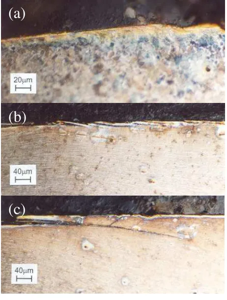
At low Tγ/Α oxidative wear was seen to occur on
both wheel and rail discs. The disc surfaces turned a rusty brown colour. Closer examination of the wear surface of the wheel disc revealed abrasive score marks and evidence of the oxide layer breaking away from the surface. Figure 4a shows the subsurface morphology of
the wheel disc. At the surface the oxide layer is just visible. There is a very small amount of deformation just below the wear surface of the disc.
As Tγ/Α was increased, the wear mechanism
altered. The wheel material appeared to be wearing by a delamination process. Closer examination of the wheel disc surfaces revealed that this was the case (see figure 4b). It could be seen that a larger amount of plastic
deformation was occurring below the wheel disc wear surface and crack formation just below the surface was visible which was leading to thin slivers of material breaking away from the surface. As Τγ/Α was increased further these cracks were seen to alter direction from running parallel to the wear surface and turning up to turning down into the material causing larger chunks of material to break away. These observations tie in with those of previous work [12].
0
500
1000
1500
2000
2500
3000
0
20
40
60
80
100
120
T
γ
/A (N/mm
2)
Wear Rate (
g/m/mm
2
)
K
1K
2K
3Regime Tγ/A (N/mm2) Wear Rate (µg/m/mm2)
K1 Tγ/A < 10.4 5.3Tγ/A
K2 10.4 < Tγ/A < 77.2 55
K3 77.2 < Tγ/A 61.9Tγ/A
[image:5.612.105.507.383.683.2]figure 4 R8T wheel material disc sub-surface morphology: (a) Tγ/A = 0.2 N/mm2; (b) Tγ/A = 16 N/mm2; (c) Tγ/A = 28 N/mm2
MODELLING METHODOLOGY
The modelling methodology for the estimation of wheel profile evolution wear is made up of three main elements:
1. a multi-body model of the railway vehicle, used to evaluate as function of time the number and position of wheel/rail contact points and the
resulting global contact force and creepage components.
2. a contact model to derive the local pressure, traction and creepage distributions within the contact area using inputs from the multi-body modelling.
3. wheel profile evolution calculation based on the wear model developed from twin disc wear testing and using inputs from the local contact analysis.
The complete procedure is schematically represented in figure 5. Starting from the vehicle
characteristics and initial wheel and rail profiles, a wear sequence reproducing the vehicle mission profile is simulated using the multi-body vehicle model. For each time step of the simulation, the results in terms of global
contact parameters (position of contacts, resulting contact forces and creepages) are used to perform a local contact analysis which provides as output the distribution of frictional work inside the contact patch. Finally, the modification to wheel profiles produced by the wear sequence is computed using the wear model based on the experimental results obtained from twin disc wear tests. By subtracting this modification to the initial wheel profile, the worn wheel profile is determined. This wear loop can be repeated several times to predict wear progress on wheel surface.
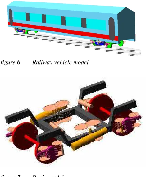
MULTI-BODY VEHICLE MODEL
The railway vehicle model used to evaluate wheel/rail contact forces as function of wheelset service was developed in the ADAMS/Rail environment. The model includes a mathematical description of the full vehicle where car body, bolsters, bogie frames and wheelsets are treated as rigid bodies, while primary and secondary suspensions are represented by means of linear and non linear elastic and damping elements (figures 6 and 7).
Vehicle Data
Vehicle Mission Profile
Rail Profile
Wheel Profile
MULTI-BODY MODEL OF
RAILWAY VEHICLE
Contact Patch Geometry
Position of Contacts
Global Contact Forces
Global Slip
LOCAL CONTACT ANALYSIS
Distribution of force and slip in the
contact
WHEEL PROFILE EVOLUTION CALCULATION Wear Coefficients
from Twin Disc Testing
figure 5 Modelling methodology
(a)
(b)
[image:6.612.110.502.575.703.2]figure 6 Railway vehicle model
figure 7 Bogie model
Vehicle parameters were defined with reference to an ETR470 Pendolino railway vehicle. This kind of
vehicle is particularly interesting for wheel wear analysis because it can be operated at high levels of cant deficiency, which leads to high values of lateral contact forces and creepages and therefore to accelerated wheel wear [6]. More details about the vehicle model are
reported in [1].
The dynamic analysis method is used within ADAMS/Rail to calculate, as a function of time, all quantities related to the dynamic behaviour of the vehicle and the wheel/rail contact. In order to integrate the wheel wear calculation and dynamic analysis results these have been enhanced to include quantities such as contact patch dimensions and actual rolling radius, necessary for wear evaluation.
LOCAL CONTACT ANALYSIS
ADAMS/Rail provides information about the load and tractions applied to the whole wheel/rail contact patch and its location. In this model it is assumed that the contact between the wheel and rail can be approximated by an elliptical contact patch. This allows the use of a faster solution method to determine the traction and slip distribution within the contact.
ADAMS/Rail provides the total normal force, the traction applied and the semi-axes a and b for each
elliptical contact patch and it is from these values that local contact analysis is performed. Each elliptical contact patch is discretised into strips. Each strip is then divided into equal sized cells. The contact analysis calculates traction, T, pressure, p, and slip, γ, for each
cell (see figure 8) from the leading edge of the contact,
sequentially to the rear. The forces determined for each cell are compared to slip/adhesion criteria enabling slip and adhesion regions to be identified and the slip magnitude and direction to be determined. This approach is similar to the method employed in the FASTSIM algorithm [10].
Lateral Creepage
Longitudinal Creepage
Spin Creepage
(a)
Cell
Ty, γy
Tx, γx
x (rolling direction) y
[image:7.612.331.524.216.555.2](b)
figure 8 Output from: (a) ADAMS/Rail and (b) local
contact analysis
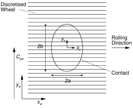
WHEEL PROFILE EVOLUTION
To determine the evolution of the wheel profile as it wears, the wheel profile was discretised into
figure 9). By aligning the discretisation strips in this
way, wear calculated for each strip could be summed to calculate the wear depth for that region of the wheel profile.
The positioning of the wheel strips was achieved by setting a co-ordinate system for the wheel and deciding on an interval width for discretisation. The strip width can be reduced to improve resolution or increased to reduce computing time. For subsequent pressure, traction and slip calculations the contact is normalised giving the relationship between the wheel and ellipse co-ordinate systems as:
b C y
ye = w− pw (1)
where ye is the y value in the ellipse co-ordinate system,
yw is the y value in the wheel co-ordinate system, Cpw is
the contact point on the wheel and b is the ellipse
semi-axis.
Cpw
xw
yw
Rolling Direction
Contact
2a 2b
Discretised Wheel
ye
xe
figure 9 Discretised wheel and elliptical contact co-ordinate systems
A value for Tγ/A was calculated for each cell in
the local contact analysis and compared to the wear regimes identified from wear test data (as shown in
figure 3). The corresponding wear coefficient, K, for
each wear regime was used to calculate the wear volume per cell, WDcell. The depth of wear per cell is
then given by:
ρ γ V t
K A T
WDcell = ∆ (2)
where V is the rolling velocity, ρ is the density of the
wheel steel and ∆t is the duration of the contact time
step.
Each cell in the contact ellipse has an associated wear depth. The wear on each strip (in the rolling direction) is summed and that depth removed from the
corresponding circumferential strip on the wheel. The contact time interval, ∆t, in the output data from
ADAMS/Rail is not necessarily equal to one revolution of the wheel. It is generally observed that wear occurs uniformly over a wheel circumference. Therefore it is reasonable to proportion the wear caused by a given patch location over the time, ∆t, equally over the whole
circumference of the wheel according to the ratio
V∆t/2πR, where R is the wheel radius. This is carried
out for each strip in the contact patch to determine the wear caused by that contact over the time, ∆t. Each
contact patch obtained from the ADAMS/Rail
simulation is treated in the same way to obtain the worn wheel profile. This procedure is shown schematically in
figure 10.
Cpw
0 - t
2t - 3t t - 2t
3t - 4t
4t -5t
Accumulated Wear Depth Wheel Position
figure 10 Summation of the wear per strip to give total wear depth
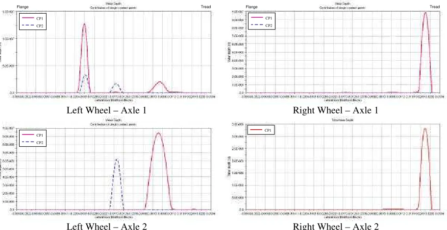
SAMPLE RUNS
The wear prediction algorithm has been introduced as built-in tool in ADAMS/Rail. Runs have been carried out for an ETR470 Pendolino vehicle running on sample
right hand curves of varying radius as detailed in table 1. The wear predictions for each length of track are
shown in Figures 11 to 13. Wear is shown for
individual contact patches. Within ADAMS/Rail these are totalled and then used to update the wheel profile.
Curve Radius (m)
Vehicle Speed (km/h)
Gauge (m)
Cant (m)
370 120 1.438 0.15
600 160 1.438 0.15
960 160 1.438 0.15
table 1 Track parameters for sample runs carried
As expected the greatest wear occurs on the outside (left) wheel of the leading axle as this is where the contact conditions are at their most severe. As the radius of curvature increases the magnitude of wear decreases and the position where the wear is occurring alters. For example, the wear on the leading outside (left) wheel moves from the flange to the tread.
Simple validation has been carried out for the wear algorithm [24]. This involved running a sample of
ADAMS/Rail data consisting of a vehicle running on a length of track made up of a straight section, curve and then straight again. After 33000 wheel revolutions, where the vehicle has been repeatedly running over the above sample of track, the wear depth for the tread on the inside wheel on the leading axle was 3µm. It has been observed that for a wheel rolling along a straight track for 33000 cycles, approximately 1µm of wear occurs [25]. Whilst this data is for a different vehicle
and track configuration, the amount of wear is of a similar order. Especially considering that for the ADAMS/Rail result the contact patch position does not vary over a large region. The result of this is to concentrate the wear to a small region of the wheel.
DISCUSSION
While the integrated multi-body dynamics and wear prediction procedure outlined provides a powerful tool for railway wheel wear assessment, further work is required to improve a number of areas.
As yet only a simple validation has been carried out. A full validation procedure is being undertaken as part of the HIPERWheel project. Demonstrators are currently being manufactured for this purpose and full-scale tests will be carried out.
The contact patch is assumed to be elliptical within ADAMS/Rail to facilitate quicker solution times by using FASTSIM for the local contact analysis. Clearly real wheel/rail contacts will not be elliptical in shape. Improvements could be made by using non-elliptical contacts from ADAMS/Rail combined with local contact analysis using CONTACT to provide a more realistic representation of the contact. The advantages, however, have to weighed up against the substantial increase in computing time that will result.
At present wheel profile up-dates are carried out within ADAMS/Rail after a block of wheel cycles, rather than after each cycle, to speed up calculations. Evolution of the wheel profile has a large impact on vehicle dynamics so continual updating may give more accurate results. Although this again would have to be weighed up against increase in computing time.
CONCLUSIONS
A model has been developed to predict the wear of railway wheels. This assumes wear is related to Tγ/A,
where T is tractive force, γ is slip at the wheel/rail
interface and A is contact area. Twin disc testing of rail
and wheel materials was carried out to generate wear coefficients for use in the model.
Left Wheel – Axle 1 Right Wheel – Axle 1
[image:9.612.77.536.464.703.2]Left Wheel – Axle 2 Right Wheel – Axle 2
figure 11 Sample ADAMS/Rail output for a 370m radius curve
CP1 CP2
CP1 CP2
CP1
CP1
Left Wheel – Axle 1 Right Wheel – Axle 1
[image:10.612.80.536.61.296.2]Left Wheel – Axle 2 Right Wheel – Axle 2
figure 12 Sample ADAMS/Rail output for a 600m radius curve
Left Wheel – Axle 1 Right Wheel – Axle 1
[image:10.612.76.538.328.580.2]Left Wheel – Axle 2 Right Wheel – Axle 2
figure 13 Sample ADAMS/Rail output for a 960m radius curve
The model has been incorporated into
ADAMS/Rail, which produces multi-body dynamics simulation of a railway wheelset. The methodology for predicting the evolution of a railway wheel profile is made up of three stages: ADAMS/Rail outputs contact conditions at the wheel/rail interface; simplified theory of rolling contact is then used to discretise the contact patches and calculate traction and slip within each; finally the wear coefficients are used with the tractions
and slips to predict the wear and hence the change of wheel profile.
This simulation routine will be used as part of a CAE package for assessing wheelset durability for the design of new wheelsets.
The model has been applied to multi-body simulation of a passage around sample track lengths. For a simple validation case the worn profile is quantitatively similar to published data.
CP1 CP2
CP1 CP2
CP1 CP2
CP1
Flange Tread Flange Tread
CP1 CP2
CP1 CP2
CP1 CP2
CP1
Acknowledgments
The work reported in this paper was carried out as part of the European Community funded project
HIPERWheel (contract number: G3RD-CT2000-00244).
References
1. STANCA M, STEFANINI A & GALLO, R.,
Development of an integrated design methodology for a new generation of high performance rail wheelsets, Proceedings of the 16th European MDI User Conference,
Berchtesgaden, Germany, 14-15 November, 2001
2. JENDEL T, Prediction of wheel profile wear
-comparisons with field measurements,
Proceedings of the International Conference on Contact Mechanics and Wear of Rail/Wheel Systems, Tokyo, Japan, 25-28 July, pp 117-124,
2000
3. FRIES R H & DÁVILA C G, Wheel wear predictions
for tangent track running, Transactions of the ASME, Journal of Dynamic Systems, Measurement, and Control, vol 109, pp 397-404, 1987
4. PEARCE T G & SHERRATT N D, Prediction of wheel
profile wear, Wear, vol 144, pp 343-351, 1991
5. ZOBORY I, Prediction of wheel/rail profile wear,
Vehicle System Dynamics, vol 28, pp 221-259, 1997
6. ROBERTI R & BRUNI S, Development of operations
of tilting train on Italian network, Proceedings of
the WCRR, Köln, Germany, 25-29 November, 2001
7. KALKER J J, Three-Dimensional Elastic Bodies in
Rolling Contact, Kluwer Academic Publishers, 1990
8. KIK W & PIOTROWSKY J, Some new results in rolling contact, Vehicle System Dynamics, vol 18,
pp 223-242, 1996
9. PASCAL, J P, About multi-Hertzian contact
hypothesis and equivalent conicity in the case of S1002 and UIC60 wheel/rail profiles, Vehicle System Dynamics, vol 22, pp 57-78, 1993
10. KALKER J J, A fast algorithm for the simplified theory of rolling contact, Vehicle System Dynamics, vol 11, pp 1-13, 1982
11. BRAGHIN F, BRUNI S &RESTA F, Wear of railway wheel profiles: a comparison between experimental results and a mathematical model,
Supplement to Vehicle System Dynamics, vol 37, pp
478-489, 2003
12. BOLTON P J, CLAYTON,P & MCEWEN, I J, Wear of rail and tyre steels under rolling/sliding
conditions, ASLE Transactions, vol 25, no 1, pp
17-24, 1982
13. HEUMANN H, Grundzuge du fuhrung du Shienenfahrzeuge, R Oldenburg, Munich, 1954
14. MARCOTTE P P, CALDWELL W N & LIST H A,
Performance analysis and testing of a conventional three-piece freight car truck retrofitted to provide axle steering, ASME Winter Meeting, 1978
15. GHONEM H & GONSALVES R, Comparative performance of type II trucks, Canadian Pacific Department of Research, Report No. 5576-78, 1978 16. GHONEM H & KALOUSEK J, The use of angle of
attack measurements to estimate wear under steady state rolling conditions, International Conference on Wheel/Rail Load and Displacement
Measurement Techniques, Cambridge, MA, 1981
17. VOGEL R & KUREK E G, Railroad Track - Theory and Practice, Ed. Fastenrath, F, Frederick Under
Publishing Co, 1981
18. KUMAR S & RAO D L P, Wheel-rail contact wear, work, and lateral force for zero angle of attack - a laboratory study, Transactions of the ASME, Journal of Dynamic Systems, Measurement, and Control, Vol. 106, pp 319-326, 1984
19. ELKINS J A & EICKHOFF B M, Advances in non-linear wheel/rail force prediction methods and their validation, ASME Winter Annual Meeting, 1979
20. BOLTON P J & CLAYTON P, Rolling-sliding wear damage in rail and tyre steels, Wear, vol 93, pp
145-165, 1984
21. MCEWEN I J & HARVEY R F, Full scale wheel-on-rail wear testing: comparisons with service wear and a developing theoretical predictive method,
Lubrication Engineering, vol 1, pp 80-88, 1985
22. ZAKHAROV S M & ZHAROV I A, Simulation of mutual wheel/rail wear, Proceedings of the 5th International Conference on Contact Mechanics and Wear of Rail/Wheel Systems, Tokyo, Japan, 25-28
July, pp 125-130, 2000
23. GARNHAM J E & BEYNON J H, The early detection of rolling-sliding contact fatigue cracks, Wear,
1991, Vol. 144, pp 103-116, 1991
24. FLETCHER D I & BEYNON, J H, Development of a machine for closely controlled rolling contact fatigue and wear testing, Journal of Testing and Evaluation, vol 28, no 4, pp 267-275, 2000
25. WARD A, LEWIS R & DWYER-JOYCE, R S, Incorporating a railway wheel wear model into multi-body simulations of wheelset dynamics, in press, Proceedings of the 29th Leeds-Lyon Symposium on Tribology, Leeds, 3-6 September,
2002
26. KALKER J J