AFIPS
CONFERENCE
PROCEEDINGS
VOLUME 24
1963
FALL JOINT
COMPUTER
CONFERENCE
1963
SPARTAN BOOKS, INC.
Baltimore, Md.
The ideas and opinions expressed herein are solely those of the authors and are not necessarily repre-sentative of or endorsed by the 1963 Fall Joint Computer Conference Committee or the American Federation of Information Processing Societies.
Library of Congress Catalog Card Number: 55-44701
Copyright © 1963 by American Federation of Information Processing Societies, P. O. Box 1196, Santa Monica, California. Printed in the United States of America. All rights reserved. This book or parts thereof, may not be reproduced in any form without permission of the publishers.
Sole Distributors in Great Britain, the British Commonwealth and the Continent of Europe:
CLEA VER-HUME PRESS 10-15 St. Martins Street
London W. C. 2
LIST OF JOINT COMPUTER CONFERENCES
1. 1951 Joint AlEE-IRE Computer Confer-ence, Philadelphia, December 1951 2. 1952 Joint AIEE-IRE-ACM Computer
Conference, N ew York, December 1952 3. 1953 Western Computer Conference, Los
Angeles, February 1953
4. 1953 Eastern Joint Computer Conference, Washington, December 1953
5. 1954 Western Computer Conference, Los Angeles, February 1954
6. 1954 Eastern Joint Computer Conference, Philadelphia, December 1954
7. 1955 Western Joint Computer Conference, Los Angeles, March 1955
8. 1955 Eastern Joint Computer Conference, Boston, November 1955
9. 1956 Western Joint Computer Conference, San Francisco, February 1956
10. 1956 Eastern Joint Computer Conference, New York, December 1956
11. 1957 Western Joint Computer Conference, Los Angeles, February 1957
12. 1957 Eastern Joint Computer Conference, Washington, December 1957
13. 1958 Western Joint Computer Conference, Los Angeles, May 1958
14. 1958 Eastern Joint Computer Conference,
P~iladelphia, December 1958
15. 1959 Western Joint Computer Conference, San Francisco, March 1959
16. 1959 Eastern Joint Computer Conference, Boston, December 1959
17. 1960 Western Joint Computer Conference, San Francisco, May 1960
18. 1960 Eastern Joint Computer Conference, New York, December 1960
19. 1961 Western Joint Computer Conference, Los Angeles, May 1961
20. 1961 Eastern Joint Computer Conference, Washington, December 1961
21. 1962 Spring Joint Computer Conference, San F,rancisco, May 1962
22. 1962 Fall Joint Computer Conference, Philadelphia, December 1962
23. 1963 Spring Joint Computer Conference, Detroit, May 1963
24. 1963 Fall Joint Computer Conference, Las Vegas, November 1963
Conferences 1 to 19 were sponsored by the National Joint Computer Com-mittee, predecessor of AFIPS. Back copies of the proceedings of these conferences may be obtained, if available, from:
• Association for Computing Machinery,14 E. 69th St., New York 21,N. Y.
• American Institute of Electrical Engineers, 345 E. 47th St., New York 17, N. Y.
• Institute of Radio Engineers, 1 E. 79th St., New York 21, N. Y. Conferences 20 and up are sponsored by AFIPS. Copies of AFIPS Con-ference Proceedings may be ordered from the publishers as available at the prices indicated below. Members of societies affiliated with AFIPS may obtain copies at the special "Member Price" shown.
Volume
I
List Price20 $12.00
21 6.00
22 8.00
23 10.00
24 16.50
1
M ember
I
PublisherPrice
$7.00 Macmillan Co., 60 Fifth Ave., New York 11,
N.Y.
6.00 National Press, 850 Hansen Way, Palo Alto,
Calif.
4.00 Spartan Books, Inc., 301 N. Charles St.,
Baltimore 1, Md.
5.00 Spartan Books, Inc.
8.25 Spartan Books, Inc.
NOTICE TO LIBRARIANS
This volume (24) continues the Joint Computer Conference
Proceedings (LC55-44701) as indicated in the above table. It
is suggested that the series be filed under AFIPS and cross referenced as necessary to the Eastern, Western, Spring, and Fall Joint Computer Conferences.
CONTENTS
Page Page
vii Preface vii
PROGRAMMING-EXPERIMENTAL
1 An Experiment in Non-Procedural Programming J. H. KATZ 1
W. C. MCGEE
15 Simulation of an Assembly of Simplified Nerve Cell R. E. SEARS 15
Models on a Digital Computer S. M. KHANNA
27. Cyclops-I: A Second Generation Recognition System T. MARILL 27
A. K. HARTLEY D. L. DARLEY T.G.EvANS B. H. BLOOM D. M. R. PARK T. P. HART
35 Simulation of a Turning Machine on a Digital Computer R. W. COFFIN 35
H. E. GOHEEN W. R. STAHL COMPUTER MEMORIES
45 The Rope Memory: A Permanent Storage Device P. KUTTNER 45
59 A 300 Nanosecond Search Memory C. A. ROWLAND 59
W. O. BERGE
67 ANew Technique for Using Thin Magnetic Films B.A. KAUFMAN 67
as a Phase Script Memory Element E. ULZURRUN
77 Laminated Ferrite Memory R. SHAHBENDER 77
C. WENTWORTH K.LI S. HOTCHKISS
J. RAJCHMAN
91 A Large Capacity Cryoelectric Memory With Cavity L.L.BVRNS 91
Sensing D. A. CHRISTIANSEN
R. A. GANGE
101 Fixed, Associative Memory Using Evaporated Organic M. H. LEWIN 101
Diode Arrays H. R. BEELITZ
J. A. RAJCHMAN
MULTIPROCESSOR COMPUTER SYSTEMS
107 Generalized Multiprocessing and Multiprogramming A. J. CRITCHLOW 107
Systems
127 Organizing and Programming a Shipboard Real-Time G. G. CHAPIN 127
Page Page
139 A Multiprocessor System Design M. E. CONWAY 139
147 A Probabilistic Analysis of Computing-Load Assignment M. AOKI 147
in a Multi-Processor Computer System G. ESTRIN
R. MANDELL INFORMATION RETRIEVAL
161 A Discrimination Method for Automatically Classifying J. H. WILLIAMS, JR. 161
Documents
167 The Direct Access Search System 1. A. W ARHEIT 167
173 A Flexible Direct File Approach to Information J.OLMER 173
Retrieval on a Small to Medium Size Computer
183 Experience With a Generalized Information Processing M. KOSAKOFF 183
System D. L. BUSWELL
C01VIPUTER ORGANIZATION
193 A Search Memory Subsystem for a General Purpose A. KAPLAN 193
Computer
201 The Logical Organization of the PB 440 Micro- E. O. BOUTWELL, JR. 201
programmable Computer E. A. HOSl\JNSON
215 Application of Pushdown-Store Machines R. J. EVEY 215
229 An Interrupt Control for the B5000 Data Processor R. V. BOCK 229
System
243 The Mechanization of a Push-Down Stack C. B. CARLSON 243
HYBRID ANALOG-DIGITAL COMPUTATION
251 Effects of Digital Execution Time in a Hybrid Computer T. MIURA 251
J. IWATA
267 Corrected Inputs-A Method for Improving Hybrid R. GELMAN 267
Simulation
277 A Hybrid Analog-Digital Differential Analyzer System J. V. WAIT 277
MASS STORAGE SYSTEMS
295 Review and Survey of Mass Memories L. C. HOBBS 295
311 Investigation of a Woven Screen l\/fass Memory System J. S. DAVIS 311
327 ANew High Density Recording System: The IBM J. D. CAROTHERS 327
1311 Disk Storage Drive with Interchangeable R. K. BRUNNER
Disk Packs
"J.
L. DAWSONM. O. Hf\LFHILL R. E. KUBEC
341 An Engineering Description of the Burroughs R. W. JACK 341
Disk File R. G. GROOM
R. A. GLEIM
351 A Multiple-Access Disc File 1. L. WIESELMAN 351
R. STUART-WILLIAMS D. K. SAMPSON
NATURAL LANGUAGE PROCESSING
365 Syntactic Analysis of English by Computer-A Survey D. G. BOBROW 365
389 The Computer-Stored Thesaurus and its Use in Concept C. A. SHEPHERD 389
Processing
397 Syntactic Structure and Ambiguity of English S. KUNO 397
Page Page
419 A Tape Dictionary for Linguistic Experiments J. L. DOLBY 419
H. L. RESNIKOFF E. MACMuRRAY REAL-TIME SIMULATION
425 Hybrid Simulation of an Aircraft Adaptive Control P. W. HALBERT 425
System
437 A Computer Driven Simulation Environment for E. A. ROBIN 437
Air Traffic Control Studies R. S. PARDEE
D. L. SCHEFFLER F. C. HOLLAND A. G. HALVERSON
445 Hybrid Techniques for Real-Time Radar Simulation R. L. BOYELL 445
H. RUSTON
459 A Digital Computer for Real-Time Simulation M. PALEVSKY 459
J. V. HOWELL
MEMORY-ORIENTED COMPUTERS
473 Systems Implications of New Memory Developments S. G. CAMPBELL 473
481 A Modified Holland Machine
W;
T. COMFORT 481489 Associative Logic for Highly Parallel Systems R. R. SEEBER 489
A. B. LINDQUIST
495 Some Applications for Content-Addressable Memories R. H. FULLER 495
G. ESTRIN PROGRAMMING-APPLIED
509 A Computer Aid for Symbolic Mathematics L. C. CLAPP 509
R. Y. KAIN
519 Stock Maintenance by Telephone-One Step Towards G. P. LEWETT 519
Integrated Manufacturing Control in a Multi- S. CHOOLFAIAN
Shop Manufacturing Complex
529 Information Handling in an Arms Control Inspection L. F. MATHISON 529
Environment
INPUT-OUTPUT EQUIPMENT
535 An Approach to Manufacturing Control Using C. A. R. KAGAN 535
Inexpensive Source to Computer Communications R. TEVONIAN
551 Engineering Characteristics of Cylindrical Thin Film B.A.KAUFMAN 551
Parametrons For Use in Digital Systems W. G. PFEIFFER
V. K. RANDERY A. J. KOLK
565 Single Capstan Tape Memory R. A. KLEIST 565
M. A. LEWIS B. C. WANG
577 The Evolution of an Army-Navy Militarized Digital D. J. MORRISON 577
Magnetic Tape System For Field Computer D. H. TYRRELL
Applications J.J. STALLER
591 IBM 7340 Hypertape Drive R. A. BARBEAU 591
J. 1. AWEIDA
COMPUTERS AS A SOCIAL FORCE
603 Computer Applications at the Frontiers of Biomedical W. R. ADEY 603
Research
609 A More Rational System of Justice Through R. F. C. HAYDEN 609
Information Processing
619 The Computer in Education: Malefactor or Benefactor ROBERT L. EGBERT 619
PREFACE
This volume provides the permanent record of the Technical Program of the 1963 Fall Joint Computer Conference.
In organizing the program, specific attention was directed toward pro-viding a broad cross-section of material which covered all aspects of the field and reversing the trend toward concentration on software apparent in the past few Conferences. The accomplishment of this goal is exhibited by the large number of papers contained herein, encompassing hardware, software, systems, and applications. In addition, a group of papers pre-sents specific proposals for the application of computers to important social problems.
The volume contains the full text of the 55 papers~ selected for
pres-entation and discussion at the Conference. It represents the culmination
of much hard work by many people-in particular, the authors, to whom we are indeed grateful for their contributions; the Technical Program Committee, session chairmen, panelists, and reviewers who put together the program; and the entire Conference Committee whose untiring efforts made the Conference possible.
vii
JAMES D. TUPAC
Conference Chairman
AN EXPERIMENT IN NON-PROCEDURAL PROGRAMMING
Jesse H. Katz and William C. McGee TRW Computer Division Thompson Ramo Wooldridge Inc.
Canoga Park, California
1. INTRODUCTION
Computer processes have traditionally been specified by means of procedural languages. That is, a computer program is generally ex-pressed as a sequence of steps.
Three reasons can be cited to explain why pro-grams are written in a step-by-step fashion. First, digital computers themselves, for reasons of economy, operate sequentially and thus re-quire step-by-step directions called instructions. Thus, in the early days of computers, programs written at the machine language level were--of necessity--one hundred percent procedural. The methods of machine language programming un-doubtedly had an impact on the specification of the higher-order languages developed subse-quently (e.g., ALGOL, COBOL, FORTRAN), with the result that these higher-order lan-guages are also largely procedural.
A second reason for writing programs as sequences of steps is that many computer proc-esses are inherently sequential; i.e., certain things must be done before other things are done. This is particularly true of numerical processing.
Third, we use step-by-step programming in many cases simply because we find it easier to think of a process as a sequence of steps, re-gardless of whether the process is truly
sequen-tial or not. In thi~ way, we limit to a
manage-able number those things which must be kept in mind at anyone time.
1
The extent to which procedural languages are now ingrained makes it certain that they will be with us for many years to come. But the per-petuation of these languages-to say nothing of their proliferation-is not without disadvan-tages. The major disadvantage is the difficulty of specifying computer processes in a manner which is independent of the computer on which they are to be carried out.
As a simple example, consider the evaluation of the expression
y==ax+b
On a one-address computer, the machine lan-guage procedure for this process might be ex-pressed as follows:
CLA X MPY A
ADD B STO Y
On a three-address computer, the procedure would be quite different:
MPY A/X/TEMP
ADD TEMP/B/Y
Clearly, the procedure for this process is strongly machine dependent.
The more sophistica ted languages like ALGOL and FORTRAN overcome problems like
the one illustrated above by admitting the
non-procedural specification of certain arithmetic processes. In FORTRAN, the process is ex-pressed simply as
2 PROCEEDINGS-FALL JOINT COMPUTER CONFERENCE, 1963
Such statements imply an ordering of the oper-ations to be carried out (Le., that dictated by the rules of algebra), but are properly classed as non-procedural since the procedure for carry-ing out the required operations is not explicitly stated.
By means of such non-procedural specifica-tions, large parts of a computer process can be stated in an entirely non-procedural way in a language like FORTRAN, if one is willing to construct sufficiently long and complex expres-sions. However, most computer processes also require operations which cannot be expressed non-procedurally in a language like FORTRAN. The main culprits are conditional operations, i.e., operations which are dependent on values of input data, and input/output operations.
With such problems in mind, workers in data processing theory have been giving increasing attention to non-procedural programming guages. A non-procedural programming lan-guage may be defined as one in which a com-puter process is expressed solely in terms of the
results of the process, rather than in terms of a procedure by which the results are to be pro-duced. In engineering terms, the non-procedural language allows the programmer to define the
final state of the computer as a function of its
various possible initial states.
Since machine language will remain largely procedural, at least in the foreseeable future, a non-procedural language implies the need for a mechanism for transforming a non-procedural specification into a machine language program. Such a mechanism will be similar in function to current compilers; but because its input will differ fundamentally from that of current com-pilers, this mechanism might be better termed a procedure-writer. The essential feature of the procedure-writer is that the production of a step-by-step procedure is taken completely out of the hands of the programmer. As a conse-quence, the procedure-writer is free to develop procedures which are most appropriate to the computer which will execute them.
With this introduction, we shall now discuss a completed phase of a corporate sponsored re-search project being carried out in the TRW Computer Division of Thompson Ramo
Wool-dridge Inc. The aim of this research project is' to explore techniques for developing machine-independent software. As a manufacturer of computers, TRW is faced with a major problem common to the industry: the need to repeat the development of software for each newly de-veloped computer. We feel that by bringing to bear the techniques of automatic programming qn software programs themselves, the time and cost of developing new computers and their attendant software can be cut significantly.
As part of our investigation, we have selected a typical software item, a conventional symbolic assembly program, and have derived a non-procedural specification of this process. For a non-procedural language, we turned to the In-formation Algebra, which was developed by the Language Structure Group of the CODASYL Development Committee.! Although intended primarily as a theoretical development, the In-formation Algebra proved quite adequate as a non-procedural programming language. The specification of the assembly program will be discussed in Section 3 of this paper, but first we shall describe the fundamental concepts of the Information Algebra itself.
2. BASIC CONCEPTS OF 1'HE INFORMATION ALGEBRA
An essential feature of the Information Alge-bra is the manner in which the data involved in
a process are represented. For each property
in the process, a property value set is defined
which contains all the possible values which the
property can assume. For example, if employee
number is a property, its value set might con-sist of the integers between 1 and 100,000. A
coordinate set is then defined as the set of all properties involved in a process. For example, a coordinate set might consist of the properties
employee number, employee age, and employee sex.
A property space is defined as the set of all points which can be found by taking one value from the value set of the first property, one value from the value set of the second property, and so forth, up to and including one value from the value set of the last property in the
coordi-nate set. For the coordicoordi-nate set (employee
AN EXPERIMENT IN NON-PROCEDURAL PROGRAMMING 3
p == (12345,43, M), where 12345, 43, and Mare values from the value sets of employee number, employee age, and sex respectively.
Obviously, in all but trivial processes there will be a very large number of points in the property space. In our example, if the prop-erty value sets for employee number, age, and sex contain 100,000, 100, and 2 values respec-tively, the property space will in fact contain
(100,000) (100) (2) == 20 million points. Equally obviously, not all of these points will be involved in a given processing. One of the major contributions of the Information Algebra is to give us a way of referring to and manipulating
sets of points in the property space.
The above method for representing data is
quite abstract. It does not, for example, say
anything about how data points would be stored in a computer memory or on magnetic tape; or how they would be organized to take advantage of data redundancy or irrelevancy. I t is this abstraction, in fact, which makes the Informa-tion Algepra a promising candidate for a machine-independent data processing language.
The principal function of data processing is to create output files from input files. In the Information Algebra, a file is represented as a set of points in property space and is called an
area. The creation of output files from input
files is equivalent to transforming one or more given areas (i.e., the input files) into one or more new areas (the output files). Unlike ac-tual data processing, however, this
transforma-tion does not in any way depend on the sequence
of operations, and it is sometimes helpful, in fact, to regard the transformati0ns as occur-ring simultaneously.
To express these transformations, a number
of operators or functions are provided. One
such function is the function of areas (FaA),
defined to be an operator which associates one and only one value with an area. For example, if an area A of the property space of ' the pre-vious example has been established, then a
func-tion of this area f (A) might be defined which
sums the values of age for each point in the area and divides the sum by the total number of points in the area. In other words, the func-tion computes the average age of the persons in the file represented by area A.
In addition to representing files, areas of property space can be used to represent group-ings within a file. In the illustration, it might be desired to group the points in area A such that all points in one group have age values between
o
and 4, all points in another group have agevalues between 5 and 9, and so forth. This
facility is provided by a glumping function
which partitions A into subsets of points called
elements in such a way that an element contains
all points in A having identical values for the given glumping function. The entire set of
ele-ments is called simply a glump and is denoted
G (g, A), where g is the glumping function and
A is the area.
One
of
the purposes of glumping functions isto define areas (elements are areas) which can then be operated on with a function of areas to define new areas in the property space. The
FaA used for this purpose is called a function
of a glump (FOG). The FOG creates a new
area by defining a point in property space (not necessarily a different one) for each element in a gl ump. This area is denoted
A' == H(g, A)
where A is the original area, g is the glumping
function for that area, and H is the function of
a glump which creates the new area. The points of the new area are defined by stating the values which each property in the coordinate set is to take on for each element in the glump. Since glump elements are areas, these values are stated as functions of areas. For a coordinate set with k properties q1, q;!, ... , qk, the function of a glump is written generally as
H==
q{== fJ
q~ == f:!
q:
== fkwhere the fh i == 1, 2, ... , k, are functions of an area, and the notation
i == 1,2, ... , k
means that property qj is to take the value
4 PROCEEDINGS-FALL JOINT COMPUTER CONFERENCE, 1963
The function of a glump affords a way of defining a new file from a single file. In many applications, however, a new file is to be created by simultaneously considering the data in two or more files. For such situations, the
Informa-tion Algebra introduces the area set, an ordered
set of areas (Ah A2 , • • • , An). The areas in an
area set need not be disjoint (i.e., non-over-lapping), but usually are. With such a set of areas, one can envision a process which selects a point from area Ab then selects a point from A2 and so forth until a point has been selected from each area. The set of points selected by
this process is referred to as a line, and the
points in the line are ordered since the areas in
the area set were ordered.
One can now envision this process being re-peated, e.g., selecting the same points as before from Al through An- h but a new point from An. This new set of points defines another line. Similarly, other lines may be defined, until all
possibilities have been exhausted. If the areas
contain mb m2,"" mn points respectively, a
n
total of-,-, mj lines can be formed.
i = I
Out of the totality of lines intersecting an area set, one can now envision a selection proc-ess in which only those lines meeting a certain condition are selected. The set of lines so
se-lected is called a bundle, and the condition for
selection is expressed in a bundling function.
The bundling function is a special case of a function of lines (FOL) which in general asso-ciates a single value with a line (in the same way that an FOA associates a single value with an area). The bundling function is called a
selection FOL, because it can associate only two
values with any line: true or false. The lines
in a bundle are those lines for which the asso-ciated bundling function is true. All lines for ~hich the bundling function is false are disre-garded. As will be seen later, the purpose of the bundle is to associate points in different areas.
In many processes it is desired to associate a single new record with each occurrence of matching records from two or more input files. In the Information Algebra, this is
accom-plished with a function of a bundle (FOB). An
FOB creates a new area by defining a point in
property space for each line in a bundle. The area is denoted
A'
==
F (b, AI, A2 , •• " An)where b is the bundling function, the ordered
set (Ah A2 , ••• ,An) is the area set over which
b is defined, and F is the function of a bundle which creates a new area. The points in the new area are defined in a manner similar to the way points are defined in a function of a glump; the difference is that the functions which assign values to the various properties of the coordi-nate set are now functions of lines instead of functions of areas:
r
qj==
fII q~
==
f2F
==
11 .q~
==
fkIn the next section the various functions of the Information Algebra will become clearer, as we see how they are put to use in specifying an Assembly Program.
3. APPLICATION OF THE INFORMATION ALGEBRA TO AN ASSEMBLY PROGRAM
To illustrate the application of the Informa-tion Algebra to software processes, we have selected a symbolic assembly program as a test device. Our assembler is a "subset" of the familiar SAP assembler used with the IBM 704/709/7090 family of computers; and for illustration purposes we shall assume that as-sembly is to be performed for machines in this family. In specifying this assembler, we have held its features close to the minimum so that we can concentrate here on the essentials. Nonetheless, all the necessary facilities for sym-bolic assembly are provided, including the auto-matic incorporation of subroutines from a sub-routine file.
The symbolic instructions acceptable to this assembler are of two kinds: machine instruc-tions and pseudo instrucinstruc-tions. The former con-sists of instructions carried out by the computer
(e.g., CLA, ADD, STO) ; while the latter con-sists of the following: BCD, BSS, DEC, LIB,
sum-AN EXPERIMENT IN NON-PROCEDURAL PROGRAMMING 5
Pseudo
Instruc- Function tion
BC)) Provides for assembly of one to nine words of BCD information. H1gh-order digit of address field specifies number of words set aSide. ISS Reserves number of
words specified in address field. DEC Provides for assembly
of one decimal word. LIB Provides for
incoI"]?Or-ating a subroutine from subroutine file. Symbol in location field iden-tifies subroutine.
TypeofI'e.ta in IDcation Field
blank, symbol blank, symbol blank, symbol symbol
OCT Provides for assembly" blank, of one octal word. symbol ORG Sets "loeation counter" blank
to value specified in address field.
Rat Provides for comment blank in program.
SYN Sets symbol in location symbol field "equal" to
sym-bolic address in address field.
TypeofI'e.ta Effect on in "IDeation Address Field Counter" BCD count: dec- +n, where imal integer 'n = 1,2, ••• ,9
BCD data: alpha-numeric charac-ters
decimal +n
integer
decimal +1 number
b1ll.nk +n
octal +1
number
decimal set to ~ number
(extended none address field) alphanumeric characters symbol ± none decimal
integer
Figure 1. Summary of Pseudo Instructions.
marizes the functions of the pseudo instruc-tions, including their effect on the "location counter"; and shows the types of data accept-able in their respective location fields and ad-dress fields.
3.1 Properties and Areas
The coordinate set of properties required for this problem is illustrated in Figure 2. The ith property in the coordinate set is designated qi. The general role of the several properties is as follows:
(1) ql is a sequence number associated with
each symbolic instruction in the input program and the subroutine file. This property supplies the information which
is normally supplied by the order in
which symbolic instructions are fed to the assembler.
(2) q;? through qIl correspond to the fields in
a symbolic instruction, namely: location, operation, indirect address indicator, ad-dress base, adad-dress modifier, tag, decre-ment, remarks, BCD count and BCD data. The latter two fields are relevant for the BCD instruction only.
(3) q12 is a subroutine identifier associated
(4)
(5)
(6)
with each symbolic instruction in the subroutine file.
q13 is the binary location associated with each word produced by the assembler, and q14 is the binary word itself.
q15 is an error indicator, for printing errors on the side-by-side listing.
q16 through q18 are "intermediate" prop-erties, required in establishing the in-termediate areas.
An interesting sidelight to the selection of the coordinate set of properties for this problem is the generalized apPI:oach which one is vir-tually forced to take in defining the "entities" of the process. For example, the binary output of an assembler usually takes the form of a series of records, each containing a "load address" and a number of binary words to be loaded into con-secutive locations, starting at the load address. Such an approach is obviously machine-de= pendent, since the format of the output record is strongly influenced by the peripheral equip-ment which is available to the assembler (and to the loader which loads the object program for execution). A preferable approach, therefore, is to define the binary output "records" simply as pairs of values, consisting of a load address and a binary word to be loaded at that address. The process of combining such records into a suitable physical record can then be left to the mechanism which translates the non-procedural specification into a running assembly program.
Also illustrated in Figure 2 are the input and
output areas used in the specification of the assembler, together with an indication of the relevance or non-relevance of each property to these areas. Relevance is Indicated by an X,
and non-relevance by the symbol
o.
The input areas are the symbolic input file AI;
and the symbolic subroutine file A;? A third
area Aa, which defines the mapping of symbolic
operation codes into binary operation codes, may also be viewed as an input file. The rules for this mapping could have been buried in the specification, but have been isolated in this manner to make the specification as independent as possible of the computer on which the object programs are to be run.
The purpose of the' assembler is to transform
6 PROCEEDINGS-FALL JOINT COMPUTER CONFERENCE, 1963
AREAS
PROPERlY VAlUE SETS AI AI AI AI
PROPERTIES SYIIIOlIC A.
SYIIIOlIC SYIIIIOlIC
tlPCOIIES OBJECT SlDE-BY-SiDE
WIlT SIIBROUTIE
FILE FIlE MDBIIIARY PROGRAII USTIIIG
EQUIVAlENTS
q, =SEQUEIICE IIIIIlER 1.2.- X X n n X
q, =SYII!OUC LOCATIOII b ... X X n n X
q,=SYI8lUC OPERATIOII lalpUieticdlalxllrS X X X n X
q. =SYII!OUC INDIRECT ADDRESS IIDICATOR bllIIk,' X X n n X
q, =SYIIIOUC ADDRESS BASE bllIIk,.,-..doci ... ocIII ... X X n n X
q. = SYIIBOLIC AOORESS IIODIfIER bllIIk,:t_ ... X X n n X
q, =SYWIOLIC TAG IIbIk.O.lr_.7 X X n n X
q, =SYII!OLIC DECRElENT lIbIk.dlci ... X X n n X
q.=REIINIKS 47~dIorIcIIn X X n n X
.... =SYIIIOLIC BCD COUNT 1,2,....9 X X n n X
q,,=SI'IIIOUC BCD DATA 54~..-s X X n n X
q,,=SUBROUTIE ID .,... n X n n n
q,,=BlIWIY LOCATDI I5I1i1s n n n X X
Q,.=IIIIIARYIORO 3611i1s n n X X X
q .. =ERROR CODE E n n n n X
~..=COUNT 1 1,2,... n I n n n n
---q,,=COUIIT2 1.2._ n n n n n
q,i' AUXIUARY SEQI£IICE IUIIBI l,2,... n n n n n
Figure 2. Properties and Areas for Assembler Specification.
information in area Aa, into two output areas:
A4 , which is equivalent to object program output
of an assembler; and An, which corresponds to the side-by-side listing usually produced by an assembler. Our goal, then, is to derive two ex-pressions which define each of the output areas in terms of the input areas; that is, we seek expressions of the general form
A4 == f1 (AI, A2 , A3 )
A5 == f2 (AI, A2 , Aa)
As might be expected, the functions fl and f2 are quite complicated. To simplify the notation, we have introduced a number of intermediate areas. In general, each intermediate area is a function of one or more previous intermediate areas.
3.2 Summary of Assembly Process
The process by which the intermediate areas, and eventually the final output areas, are cre-ated is outlined below. The referenced equa-tions are those in Appendix 1.
( 1) An area is constructed which consists of
those LIB instructions in the original symbolic program whose location fields
contain mutually distinct symbols. This area is then used, in conjunction with the area representing the symbolic sub-routine file, to mark each valid LIB instruction with the memory require-ment of its corresponding subroutine. Invalid LIB instructions, i.e., those with multiply-defined symbols and those for which no corresponding subroutine exists, are marked as errors. See eqs.
(1), (2), (3).
(2) The symbolic instructions in the main
symbolic program are re-sequenced to allow for the insertion of library sub-routines. (We shall return to this par-ticular operation in Section 3.3 and show in detail how it is accomplished.) The symbolic instructions belonging to the selected subroutines are also re-sequenced, so that they can be merged with the main program. The union of these two sets of instructions thus rep-resents the "full" symbolic program.
See eqs. (4), (5), (6).
vari-AN EXPERIMENT IN NON-PROCEDURAL PROGRAMMING 7
able number of words in the object pro-gram, according to the number supplied in the address field of the instruction. The next step, then, is to re-sequence the symbolic program to leave room for words generated by the BCD
instruc-tions. See eq. (7).
(4) We next strip the symbolic program of REM, LIB and SYN instructions, since these instructions produce no words of code in the object program. A new prop-erty, "auxiliary sequence number," is in-troduced to record the re-sequencing. The auxiliary sequence number is then further adjusted to reflect the "expan-sion" caused by BSS instructions. Fi-nally, with the aid of the ORG instruc-tions, the auxiliary sequence number is mapped into binary location; the ORG instructions are then stripped from the
program. See eqs. (8), (9), (10).
(5) The program, as it now stands, and the set of (stripped) SYN instructions are operated upon to produce a symbol table. All instructions whose location fields con-tain multiply-defined symbols are marked as errors. Also, any SYN instruction whose location field contains an undefined symbol is marked as an error. See eqs.
(11), (12), (13).
(6) All object program words generated by
BCD, DEC and OCT instructions are
de-veloped. See eqs. (14), (15).
(7) The set of machine instructions in the
program is then partitioned into two sub-sets: those with symbolic addresses and those with non-symbolic addresses. The two classes of machine instructions are translated separately. Any instruction whose location field contains an undefined symbol or whose symbolic operation is invalid is marked as an error. The two output files, i.e., the side-by-side listing and the object program, can now be formed merely by taking the union of appropriate areas developed along the
way. See eqs. (16), (17), (18), (19).
3.3 One Equation in Detail
The specification of the entire assembly
proc-ess can be exprproc-essed by a set of nineteen
equa-tions. These are given in Appendix 1.
At this point we shall discuss one of these equations in detail, so that greater insight might be gained into the methods of the Information
-Algebra. In step (2) of Section 3.2 it was
explained that the main symbolic program must be re-sequenced to allow for the insertion of library subroutines. The expression for this operation is eq. (4) of Appendix I, namely,
A9
==
H3 (ql, F2 (B3»
U I£(B3)where
and
B3
==
(ql:l<
ql:2, A7 , As)F2
==
(q:7==
q16:d ;H3
==
(q~==
ql+
~ q17, q~==
qbi
==
2, 3, ... , 11, 15)The components of this expression are as fol-lows:
(1) The area As represents the symbolic
pro-gram. Each valid LIB instruction con-tained in the program has been marked with the memory requirement of its cor-responding subroutine (property q16); and each invalid LIB instruction has been marked as an error.
(2) The area A7 represents the subset of As
which consists of valid LIB instructions.
(3) The expression B3 stands for a bundle
which is formed by joining every point in A7 to every point in As, and selecting only those lines for which the bundling function (ql:l
<
ql:2) is "true." In this case the bundling function means that a line is selected only if property ql (se-quence number) in the first area of thebundle (A7) is less than property ql
8 PROCEEDINGS-FALL JOINT COMPUTER CONFERENCE, 1963
F, .(B, ):PRODUCT AREA
H, (q" F, (B, )),SUBSET OF A.
Figure 3. Formation of Typical Intermediate Area.
.
while A, Band C are not associated with any LIB instruction.
(4) The function F 2 maps each line in the
bundle into a point in a "product area" in accordance with the definition
F2
==
(ql~==
q l6:dThis simply means that the property q17 (count 2) for every point in the product area is given the value of the property qlfi
(count 1) for the point in the first area
(A7) on the corresponding line. The re-maining property values for the points in the product area are, by convention, sim-ply copied from the points in the second area (As) on the corresponding lines. The result is one or more copies of each struction having "associated" LIB in-structions, with each copy holding "count I" of an associated LIB instruction (i.e., the memory requirement of the corre-sponding subroutine).
(5) The product area is now glumped by the
glumping function qh meaning that all points having the same sequence number will be in the same element. Thus, in Figure 3, F' and F" will be in the same
element, G' and G" will lie in another ele-ment, and D' and E' will occupy separate elements by themselves. The elements of this glump are then mapped into a new area, one point per element, by the
func-tion of a glump H3 , as follows:
H3
==
(q~==
ql+
l q17, q~==
qhi
==
2, 3, ... , Il, 15)By means of this expression, each point in the new area is assigned values for
properties qh qz, ... , ql1 and q15. By
con-vention, the values of all other properties become null. Essentially, the new area contains a single point for each original instruction having at least one preceding LIB instruction, but now having a se-quence number equal to the old sese-quence number plus the number of words re-quired for all subroutines called by pre-ceding LIB instructions.
(6) Finally, the area An must also include
I~ (Ba). This expression simply
repre-sents the complement of the intersection
of the bundle B:~ with As, i.e., all
tions having no preceding LIB instruc-tions (A, Band C in Figure 3) , and hence for which no sequence number adjust-ment is required. The desired area An is then the simple union of I; (B:J and the
function of a glump H3 •
4. CONCLUSIONS
The original Information Algebra report! made it clear that the Information Algebra is a powerful language which provides for a concise formulation of those processes which we term "business data processing." The work we have just described suggests that the Information Algebra is applicable to a much broader class of computer processes. In particular, its suc-cessful application to the specification of an as-sembly program suggests that it might be suit· able, with some minor extensions, as a software programming language.
AN EXPERIMENT IN NON-PROCEDURAL PROGRAMMING 9
formats. Similarly, we were able to sidestep completely the problem of the general organiza-tion of an assembly program (e.g., whether it is a "one-pass" or "two-pass" process), which is generally established by such computer char-acteristics as core size and the types and num-ber of peripheral devices available. Our specifi-cation, in short, is strictly machine-independent, and could be rendered with equal facility into a suitable procedure for any computer.
It might be noted that our example does have
machine-dependent aspects; however, these are a result of the process being specified rather than the specification technique. An assembly program by definition produces object programs for a specific computer, and the characteristics of this computer will unavoidably show up in the specification. In particular, the machine instruction format of the computer, and to a corresponding degree, the format of input sym-bolic instructions, are implicit in the specifica-tion of the assembler. This is quite a different type of machine dependency than the one we are concerned about, and in no way detracts from the machine-independency of the assembly process per se. With suitable generalizations, machine-dependent aspects of the former type can presumably be eliminated.
Of some concern to us was the fact that in developing the non-procedural specification, we were not able to avoid thinking in a step-by-step fashion. A little reflection, however, assured us that we were simply unable to adequately com-prehend all parts of a complex process at once, and were using the same kind of "thought par-titioning" which a mathematician uses in using two shorter expressions when a single longer one would do. To convince ourselves that this was indeed the case, we attempted to construct a single expression for each of the files produced by the assembly process by simple substitution of the constituent expressions. This was aban-doned when the expression became longer than a standard desk, but not before we assured our-selves that it could in principle be done.
Only one major difficulty was encountered in using the Information Algebra, that being the difficulty of mapping a single point into a set of points, where the number of such points and the values associated with each are derived
from the values associated with the given point. For such operations, it appears that an "inverse function of an area" might be a useful extension to the algebra. Except for minor notational difficulties, the Information Algebra otherwise proved to be quite adequate.
A problem of major concern which lies ahead is how a non-procedural specification is to be used to produce running programs. Two basic approaches might be used. In the first, the non-procedural specification would be intro-duced directly into the computer (with ap-propriate code transliteration) and executed interpretively. Such a process appears to be grossly inefficient with present computers, but might be feasible in computers with extensive facility for parallel operations.
The second approach, and probably the more practicable, is to translate the non-procedural specification into 'a machine-language program with a "procedure-writer" program. From the abstract nature of a non-procedural specifica-tion, it is clear that such a procedure-writer would have to know a great many details about the computer for which it is writing procedures (programs) . To keep the procedure-writer itself independent of the object computer, such details should be introduced as input param-eters rather than being buried in the
procedure-writer. It is equally clear that in addition to the
object program, the procedure-writer will also have to generate "human-procedures," i.e., pro-cedures for using the program. The approach is illustrated in Figure 4.
Since non-procedural specifications are ma-chine-independent, it is clear that the same specification can be introduced repeatedly to the procedure-writer, each time with details about different object computers, to produce different programs and usage procedures for each of the object computers.
PROCEDURE WRITER
10 PROCEEDINGS-FALL JOINT COMPUTER CONFERENCE, 1963
Finally, since the procedure-writer itself is a computer process, it can be expressed in non-procedural form and introduced to an existing procedure-writer to produce a procedure-writer for any other computer.
The price paid for machine-independent com-puter process specification, of course, is in the complexity of the procedure-writer. With such rapid advances in the art of compiler construc-tion, however, the procedure-writer appears technically feasible in the near future. When it is, a long step toward the goal of machine-independent programming will have been taken.
APPENDIX I: Assembly Program Specification
Let the symbolic input file Al be partitioned
into two subsets Al (1) and Al (2), consisting of
LIB instructions and non-LIB instructions re-spectively. Thus
A~l)
==
G(q3, AI)I
q=
"LIB"3 and
A\21
==
Aln
(A\l»Let A6 denote the set of LIB instructions whose location fields contain mutually distinct symbols. Then
(1)
where F T is the identity FOB;
BI
==
(q2:I==
q2:2/\ q16:I==
1, HI (q2, AP> ) , A~l) ) ;and
HI
==
(q;==
q2, q{6==
~ 1)Note that the complement of the intersection of
BI with A~l~ consists of all LIB instructions with
multiply-defined location fields.
By considering the symbolic subroutine file
A2 jointly with A6 , one can construct the area
A7 which represents the LIB instructions marked with the memory requirement of the subroutines which they call. Thus
A7
==
H2 (qh F1(B2»
(2)where
B2
==
(qI2:1==
q2:2, A2 , A6 )and
Hi!
==
(q{==
qb i==
1, 2, ... , 11, q{6==
~ 1)Note that each point in the complement of the
intersection of Bt with Ali represents a LIB
in-struction for which there is no subroutine in the symbolic subroutine file.
We now designate by As an area containing the following: the original symbolic program with valid LIB instructions marked with the memory requirement of corresponding subrou-tines, and with invalid LIB instructions marked as errors.
As
==
A~2) U A7 U li\ (1, I;(BJ) UFl (1, I;(B1
»
(3)where
F 1
==
(q{5==
"E")and "E" stands for "error."
Joint consideration of As with A7 enables us
to construct A9 , which represents the original
symbolic program re-sequenced to allow inser-tion of library subroutines.
where
and
B3
==
(ql:1<
ql:2, A7 , A'l ) ;F2
==
(q{7==
q16:I) ;H3
==
(q~==
ql+
~ q17, q:==
qhi
==
2, 3, ... , 11, 15)(4)
Let A~l' designate the subset of A9 consisting of valid, re-sequenced LIB instructions. Then
A~l)
==
G (q3¢q15, All)I
q ¢q = "LIB"(n3 ]5
Operating jointly on A~l) and A2, we construct
an area AlO which represents subroutine in-structions selected by LIB inin-structions and which are re-sequenced for insertion in the main program.
Alo
==
F 3(q2:1==
q12:2, A~l), At) (5)where"
F3
==
(q{==
ql:I+
ql:2, q{2==
il) The area(6)
now represents the "full" symbolic program.
Next, we further re-sequence this program to
AN EXPERIMENT IN NON-PROCEDURAL PROGRAMMING 11
Thus, we get
Al2
==
H4(qh F 4(B4»
U I~(B4)(7)
where
B4
==
(ql:l<
ql:2, G(q3, All)I
q=
"BCD", All) ;. 3
F4
==
(q{6 == qlO:l)';and
H4
==
(q~==
ql+
l (ql6-1), q[== qbi
==
2, 3, ... , 11, 15)The symbolic program is next "stripped"- of REM, LIB and SYN instructions, which pro-duce no object program code; an "auxiliary sequence number" is introduced to record the
new sequencing. It will be seen, during the next
several mappings, that this property will be transformed into the final binary location. Let
AW, A~~> and Aa> designate the subsets of
A12 consisting of SYN, REM and LIB
instruc-tions respectively. Then
Ag> == G(q3, AI2 )
I
q=
"SYN"; 3A~2J == G (qa, AI2 )
I
q=
"REM" ;s
A~Y.
==
G (qa, A12)I
<i=
"LIB" ;3
and
AW == AI2
n
(U
A~iJ
) ,i = 1
represents all other instructions in A12. The "stripped" symbolic program Ala may now be written as
Al3 == H5(qhFl (B;)) U F5 (1, I;(B5»
where
(8)
H5 == (q{== qh i
==
1,2, ... ,11, q;8==
q l - l l ) ;Fa
==
(q~8 == ql:1)Note that A~2J and A~~) above are components
of the side-by -side listing.
Next, the auxiliary sequence number is ad-justed to take into account the BSS instructions. Thus
(9)
where
B6 == (ql:1
<
ql:2, G (q3, A l3)I
q = "BSS", Al3) ; 3and
H"
==
(q(== qh i==
1,2, ... ,11,q{s
==
qjX+
l (qHi-l»The symbolic program is next stripped of ORG instructions, and binary locations are
sup-plied for all others. Designating by
AW
andAW the subsets of A14 consisting of ORG in-structions and non-ORG inin-structions respec-tively, we have
A
ii)
= G( qa, A1-l) , qa= "ORG" ; Ai~) = A14n
(Ai~) ';and can write
Al5 = H7(qI, F7(B7» U F8(1, H(B7» (10)
where
B7 = (ql:l ~< ql:2, A~~, A1~);
F7 = (qf6 = q5:1, qh = q18:1);
H7 = (qi = qi, i = 1, 2, ... , 11, qb
= q16(max {q17})
+
ql8 - max {q17} - 1);and
F8 = (qb = k - 1
+
q18:1, q~s = 0)where k is an arbitrary origin. Note that AW is a component of the side-by-side listing.
We now take the first step towards the creation of a symbol table and construct A l6,
which represents all instructions in A15 U
AW
whose location fields contain mutually distinct symbols.
(11)
where
Bs = (q2:1 = q2:2 /\ ql6:l
= 1/\ q2:l ~ "b", HI(q2, Al5 U AW), Al5 U AW)
and "b" indicates "blank." Note that all
in-structions in A15 U A~Y with' multiply-defined
symbols in their location fields will belong to the complement of the intersection of Bs with
A15 U AW.
Next, the symbol table Al7 is constructed with q2 the symbol and ql3 the corresponding binary location.
where
A17
=
AiW U F9(B9) (12)Bs = (q5:1 = q2:2, Am, AiW);
F9 = (q2 = q2:1, qh = q13:2
+
q6:1);12 PROCEEDINGS-FALL JOINT COMPUTER CONFERENCE, 1963
and
Ai7( = Al6
n
(A1~»'Each point in the complement of the
intersec-tion of BII with Ani) represents a SYN
instruc-tion whose address field symbol cannot be matched with the location field contents of any
point in A~~?
The area
A IS = Al6 U F I(1, I:(B9) U F IO(1, I2(Bs)) (13)
where
FlO = (q{5 = U ~ (q2:1 = "b") - ? "E")
represents the program of Ala U AW, with
error codes supplied. Note that G (q:1, All')
I
q3="SYN" is a component of the side-by-side listing
and that the binary location for these
instruc-tions is 0, as required.
It is convenient at this point to consider AlB
partitioned into six subsets as follows:
and
Ai~ = G( qa, AIs)
I
qa="BCD";AiW = G( qa, AIS)
I
qa="BSS" ;AfW = G( qa, AIS)
I
qa="DEC" ;Aiti = G( qa, AIS)
I
q3="OCT";A1i>
=
G( q3, AIS)I
q3="SYN";Ai~
= AISn
(.u
Al~)'
1=1
which represents machine instructions.
The expanded and translated BCD instruc-tions can be written as
S
Al9 = Fu(l, Ai~) U Fm (qlO:1
> j, Ai1»
(14)j=l
where
Fll = (q{4
=
qiHI)and the
FW,
j==
1, 2, ... , 8 constitute a classof FOB's as follows:
Fi~ = (q{ = ql:l
+
j, qi = U, i = 2, 3, ... , 11,q13 = q13:1
+
j, q14 = qPitl» j = 1, 2, ... , 8The translated DEC and OCT instructions can be written as
A20 = F I3(1, AfY U Ai~» (15)
where
I t is now convenient to regard the machine
instructions A}~) as partitioned into two
sub-sets A~I) and A\~! the former having symbolic
addresses and the latter non-symbolic addresses.
A~1) = G(gl. A1W) I gl=('l5fV2-1 "b"
I)
where V ~ is the property value set of the second
property, viz., symbolic location; thus V~
{"b"} represents the set of all possible symbols. And
A1W = A1~)
n
(Al~)'Making use of the file of symbolic operation
codes with binary equivalents A:{, we can now
represent the translated machine instructions with non-symbolic addresses by
A21 = F I4(B lO) U F 1s(1, I2(BlO» (16)
where
BlO = (qa:l = q3:2, Aa, AiW);
Fl4 = (q14 = q14:1 EB q4:2 EB q7:2 EB qS:2 EB (qla:2
+
q6:2 ~ (qS:2 = "*") - ? qS:2);and
F IS = (q14
=
0, qi5=
"E")Above it is assumed that q14:1 is the "skeleton" machine instruction, into which bits are merged according to other components of the symbolic
instruction. The character
"*,,
in F 14 is thesymbolic representation for "current value of location counter."
Making use of the symbol table, we can repre-sent translated machine instructions with sym-bolic addresses by
A22 = F 16(Bu) U F Is(l, I3(Bu» (17)
where
Bn = (q3:1 = qa:3 1\ q2:2 = qS:3, Aa, A17 , Ai~)
and
F 16 = (q14 = q14:1 EB q4:3 EB q7:a EB qS:3 EB (qI3:2
+
q6:a»Finally, we can write expressions for the side-by-side listing Aa and the object program
A4 •
As = Ai~) U AiW U Ai~ U AP; U Ali>
U Al9 U A20 U A21 U A22 (18)
A4 = F 17 (q14:1 ~ U, As) (19)
where
AN EXPERIMENT IN NON-PROCEDURAL PROGRAMMING 13
APPENDIX II: Summary of Notation
Symbol Meaning
ith area
complement of Ai with re-spect to property space
ith subset formed in a parti-tion of An
ith bundle
complement of intersection of Bj with ith area in area set
ith function of a bundle
identity function or a bundle
ith function of a bundle in a class of functions of a bun-dle
glump element which is sub-set • of An consisting of points for which glumping function gi equals c
ith function of a glump
ith property
ith property in jth area of des-ignated area set. (This no-tation differs from that in the Information Algebra report insofar as the sub-script meanings are inter-changed. We consider the revised notation more con-venient.)
q{
u
m
U ' - lA(i)
1_ n
n
1\
€
¢
EB
"b"
"E"
REFERENCE
kth component of qi:h where the value of qi:j is a vector
ith property, with a newly as-signed value
maximum value of qi in desig-natedarea
qj for the point with maxi-mum qi in designated area
property value set of jtll prop-erty
point set union
point set union of areas A~l),
A<;), ... , A~m)
point set intersection
logical AND
belongs to
concatenation operator
OR operator
if f2 true, take value of f1 ;
otherwise take value of fa
"blank"
"error"
irrelevant property value
1. An Information Algebra. Phase I
Re-port-Language Structure Group of the
CODASYL Development Committee.
SIMULATION OF AN ASSEMBLY OF SIMPLIFIED
NERVE CELLS ON A DIGITAL COMPUTER
R. E. Sears and S. M. Khanna IBM Federal Systems Division
Bethesda, Maryland
INTRODUCTION
A digital computer program simulating an assembly of simplified nerve cell models has been developed for an IBM 709 Data Process-ing System. The design of the program and the experiments performed with it were under-taken in order to develop techniques for simu-lating large assemblies of cells, and to study the network response when selected cell param-eters are varied. This paper describes the com-puter program and some of the experimental results obtained from the program.
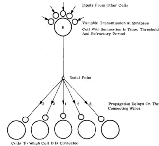
The Unit of the Network-Simplified Cell Model
The cell model used in the experiment is illustrated in Fig. 1. Impulses arrive at a given cell from other cells or input wires via the synapses. The effect of each impulse is summed in the cell, and this summed synaptic effect decays with time at a rate determined by the decay constant of the cell, Fig. 2. The accumu-lated synaptic influence in a cell is compared to the current threshold value for that cell. If the threshold value is exceeded, the cell fires and sends impulses to all its connecting wires. After firing, the cell goes into a refractory period, during which the cell is cleared of all accumulated synaptic effect, and its associated threshold is raised to a high value. The thresh-old returns to its normal value over a period of time determined by the cell refractory period constant, Fig. 3.
15
Cell With Summation In Time, Threshold Am.! Refractory Period
Propagation Delays On The Connecting Wires
00000
C .. lls To Which C,'II 13 Is ConnectedFigure 1. Cell Model Used in the Simulation, Showing
Inputs to Cell (B) and Outputs from Cell (B). (For
Simplicity Only Five of the Eleven Interconnections Are Shown.)
Communications between the cells in succes-sive layers is via the synapses. The synapses used in the program have an initially minimum transmission value. Each successive impulse arriving at a synapse increases its transmission until a maximum value is reached.
Network Organization and Properties
16
PROCEEDINGS-F ALL JOINT COMPUTER CONFERENCE, 19631.0
.9
.8
.7
.3
.2
.1
Decay Constant = 0.8
10
Time
15 20
Figure 2. Simulated Cell Decay-Fractional Change of Cell Contents with Time.
I
I
I
I
I
I
L _ _ _ I
I
Cell Refractory Constant _ _ ,4 - - - - _ c 3
L __
+-_-,3 Time
5
Figure 3. Simulated Refractory Period-Change in Cell Threshold with Time After Cell Has Fired.
4. Only symmetrically connected networks have been used with the symmetry and the layer arrangement selected primarily to sim-plify the experiments. Each cell in any layer
lllpUtWirell
Firat Layer
of Cells
Second Layer
of Celis
Figure 4. A Part of the Network Showing Intercon-nections of an In put Wire (A) and of a Cell (B) .
(For Simplicity Only Five of the Eleven Interconnec-tions Are Shown.)
connects to .and interacts with several adjacent cells in the next lower layer. The cells in the last layer connect to the output wires.
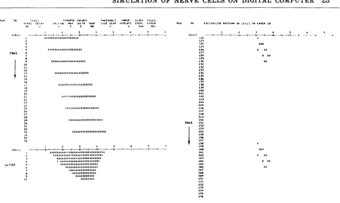
Impulses arriving on the input wires affect the cells in the first layer, first eliciting no re-sponse from the cells. Then, as the synaptic transmission increases in strength, some cells in the first layer fire. As the excitation is re-peated, the stimulus affects layers deeper and deeper in the network and, in time, the output wires. Thus, stimulus repetition creates a path of activity in the network which starts in the first layer, goes towards the lower layers, and ends at the output wires.
The network used by the program consists of 80 input wires, 800 cells in 10 layers of 80 cells each, and 80 output wires. Each cell re-ceives impulses from 11 synapses, making a total of 8,800 synapses in the network.
Basis of Simulation-HSimulated Clock"
SIMULATION OF NERVE CELLS ON DIGITAL COMPUTER 17
cell decay, cell refraction, and the connecting wire delays, are represented in terms of clock-steps. The computer is then able to perform parallel operations by stopping the clock at each time step. The actual duration of any clock-step is variable and is dependent on the number of cells fired, and the number of impulses in the network. After all the necessary operations for a unit clock-step are completed, the clock is stepped to a new value (Fig. 5). All time-dependent functions are then adjusted so that they correspond to the new time value. Because the clock-step is a quantized unit of time, the time-dependent functions are represented as step functions rather than as continuous func-tions.
Principles of Simulating Cell Functions
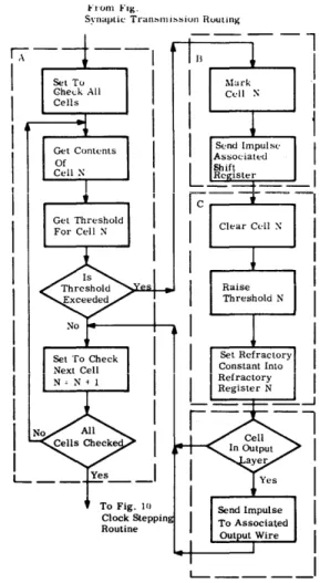
The principles of simulating the cell func-tions are illustrated in Fig. 5. Impulses arrive at the synapses at different times, due to the
propagation delays of the connecting wires. In anyone clock-step, only one impulse arrives at anyone synapse and this results in synaptic transmission to the cell to which the synapse is connected. The value transmitted is depend-ent on the history of excitation of that synapse. Initially, the transmission value in each synapse register is set to a specified minimum. Each impUlse arriving at the synapse increases the transmission by adding a specified number to the value in the synapse register, but a limit is placed on the maximum transmission value beyond which no increase takes place.
In anyone clock-step, a cell can be affected by up to 11 synapses. Synaptic effect is summed linearly to the current contents in the cell, and
this sum i~ stored -in the cell register. At each
clock-step, the contents in the cell register are compared with the contents -of that cell's threshold register, which contains the current firing threshold for the cell. If the contents in
S}'DAPR Jlec18tera 10 precedlllC layer wbldl connect to cell reg1ater
Synapses
86 85 14 83 82 81 .2 s3 84 85 86 SyDapae8 to eleven ce1l8 in the next layer
CODU!ots
No
Yes Raise Threshold
Set
Lower Raised Threshold
r---+-+---+-+---+-.... 6 Delaya
86 85 a4 83 82 8l a2 83 84 85 a6
Syoapae Regutera To 11 Cell8 In Next Layer
Sequence Of Operationa During Any One Clock Step
18 PROCEEDINGS-FALL JOINT COMPUTER CONFERENCE, 1963
the cell register are less than the cell firing threshold, the cell does not fire and its contents are decayed by replacing them with a smaller
numb~r obtained from the cell decay table by
a table lookup operation. If the contents in the cell register exceed the cell firing threshold, the cell fires and several operations· are per-formed:
• The cell register is cleared.
• The cell firing threshold is raised by plac-ing a large predetermined value in the threshold register. This value is decreased on each succeeding clock-step until it reaches its normal value, thereby simulat-ing the cell refractory period. Dursimulat-ing this period of time, the value of the cell thresh-old is determined by the contents of the threshold refractory register.
• A "one" impulse is placed in the first posi-tion of the shift register. The shift regis-ter is shifted right one position at each clock-step. Thus, the "one" impulse ap-pears at different positions of the shift register during succeeding clock-steps, thereby simulating the delay of the con-necting wires. Connected to each position of the shift register, except the first posi-tion, are the synapse registers which con-tain a synaptic transmission value and the address of the cell that receives the synaptic value. Impulses are sent to the synapse register if the "one" impulse ap-pears in the position to which they are connected.
The program consists of six main routines illustrated in simplified flow chart form in Figs. 6 through 11.
Input to the Program
The input to the program consists of the ex-perimental parameters and the stimulus. (The experimental parameters are discussed in the next section.) The stimulus, an input pattern in punched card format simulating the output of sensors, is specified by defining the input wires to be excited and the sequence of excita-tion. Stimuli characteristics, such as amplitude distribution, time duration, time sequences, etc., are represented by proper placement of impulses (punches) in the input pattern. The
Start of Program
r
-I A _ _ ---l--_
I
I
~=.,.,....-
....
Figure 6. Simulation Program Initializing Routine.
from Fig. 6 Initializing Routine
i
I
~---4---~1 L ___________________ ~
Tu Fig. l"
Synaptic Transmission Routint·