University of Southern Queensland
Faculty of Engineering & Surveying
Stereo Vision for Webcams
A dissertation submitted by
Adam G Cox
in fulfilment of the requirements of
Courses ENG4111 and ENG4112 Research Project
towards the degree of
Bachelor of Engineering - Computer Systems
Abstract
This project describes the developmental process of creating and testing a webcam
based image capture platform and library for determining the suitability of using
web-cams for stereo vision. Research and development has taken place in the field of stereo
vision for many years, however the costs involved with capture devices and computer
hardware has limited the access to the field. This has led to the requirement of a
low-cost image capture system that is capable of operating multiple capture devices
simultaneously for the application of stereo vision.
The image capture software was developed in the Microsoft Windows operating system
environment using the Microsoft DirectShow application programming interface to
ac-cess and capture video frames. The Camera Calibration Toolbox was used to perform
webcam calibration and image rectification to the captured images. Stereo
process-ing was then applied with the Dense Stereo algorithm developed by Abhijit Ogale.
The stereo disparity results were analysed for accuracy and precision to determine the
suitability of the webcam for stereo vision applications.
The outcome of the development and testing does confirm that webcams can be
op-erated simultaneously and that they can provide a suitable platform for stereo vision.
This outcome will increase the accessibility into the research of stereo vision, without
University of Southern Queensland Faculty of Engineering and Surveying
ENG4111/2 Research Project
Limitations of Use
The Council of the University of Southern Queensland, its Faculty of Engineering and
Surveying, and the staff of the University of Southern Queensland, do not accept any
responsibility for the truth, accuracy or completeness of material contained within or
associated with this dissertation.
Persons using all or any part of this material do so at their own risk, and not at the
risk of the Council of the University of Southern Queensland, its Faculty of Engineering
and Surveying or the staff of the University of Southern Queensland.
This dissertation reports an educational exercise and has no purpose or validity beyond
this exercise. The sole purpose of the course pair entitled “Research Project” is to
contribute to the overall education within the student’s chosen degree program. This
document, the associated hardware, software, drawings, and other material set out in
the associated appendices should not be used for any other purpose: if they are so used,
it is entirely at the risk of the user.
Prof F Bullen
Dean
Certification of Dissertation
I certify that the ideas, designs and experimental work, results, analyses and conclusions
set out in this dissertation are entirely my own effort, except where otherwise indicated
and acknowledged.
I further certify that the work is original and has not been previously submitted for
assessment in any other course or institution, except where specifically stated.
Adam G Cox
0050040075
Signature
Acknowledgments
I would like to acknowledge and thank Dr. John Leis for his guidance and support
throughout this project. I would also like this opportunity to thank the Faculty of
Engineering and Surveying and all the lecturers that have assisted me over the duration
of my program.
Adam G Cox
Contents
Abstract i
Acknowledgments iv
List of Figures xiii
List of Tables xv
Glossary of Terms xvii
Chapter 1 The Utilisation of Webcams for Stereo Vision 1
1.1 Project Aim . . . 2
1.2 Project Objectives . . . 2
1.3 Overview of the Dissertation Structure . . . 3
Chapter 2 Literature Review 5
2.1 Chapter Overview . . . 5
CONTENTS vi
2.2.1 Camera Calibration and Image Rectification . . . 7
2.2.2 Occlusion Reduction . . . 9
2.3 Current Computer Based Stereo Vision Systems . . . 10
2.4 Operation of Multiple Webcams . . . 11
2.4.1 USB Interface Capabilities . . . 11
2.4.2 Application Programming Interface . . . 11
2.4.3 Microsoft Windows API’s . . . 11
2.4.4 Linux and Apple API’s . . . 12
2.5 Infrared Based Game Controllers for Stereo Vision Systems . . . 13
2.5.1 Nintendo Wii . . . 13
2.5.2 Xbox Kinect . . . 14
2.6 Chapter Summary . . . 14
Chapter 3 Methodology for Software Development and Stereo Vision Evaluation 16 3.1 Chapter Overview . . . 16
3.1.1 Project Methodology . . . 16
3.2 Task Breakdown . . . 18
3.3 System Operation . . . 18
3.4 Task Analysis . . . 19
CONTENTS vii
3.4.2 Webcam Interfacing in Both Hardware and Software . . . 20
3.4.3 Development of the Multiple Camera Access Platform . . . 20
3.4.4 Webcam Image Capture . . . 21
3.4.5 Webcam Calibration for the Correction of Intrinsic and Extrinsic Parameters . . . 21
3.4.6 Image Pair Rectification and Edge Detection . . . 21
3.4.7 Stereo Processing and Disparity Mapping . . . 22
3.4.8 Software Library Development for Webcam Access . . . 22
3.5 Consequential Effects . . . 23
3.5.1 Sustainability . . . 23
3.5.2 Safety . . . 23
3.5.3 Ethical Dimensions . . . 23
3.6 Risk Assessment . . . 24
3.6.1 Risk During the Execution of the Project . . . 24
3.6.2 Risk Beyond the Completion of the Project . . . 25
3.6.3 Risk Summary . . . 27
3.7 Research Timeline . . . 27
3.8 Chapter Summary . . . 27
CONTENTS viii
4.2 Test platform Requirements . . . 28
4.2.1 USB Connectivity and Interfacing Requirements . . . 29
4.2.2 Processor Configuration . . . 29
4.2.3 Operating System . . . 29
4.3 Webcam Requirements . . . 29
4.3.1 Webcam Costs . . . 30
4.3.2 Webcam Compatibility . . . 30
4.3.3 Webcam Build Quality and Properties . . . 30
4.4 Selected Test Platforms . . . 31
4.5 Selected Webcams . . . 32
4.6 Chapter Summary . . . 33
Chapter 5 Image Capture Platform and Library Development 34 5.1 Chapter Overview . . . 34
5.2 Software Requirements and Selection . . . 34
5.2.1 Programming Language . . . 35
5.2.2 Integrated Development Environment . . . 35
5.2.3 Application Programming Interface . . . 36
5.2.4 Microsoft DirectShow Operation . . . 36
5.3 Image Capture Platform Requirements . . . 38
CONTENTS ix
5.3.2 GUI Layout . . . 39
5.3.3 Enumeration and Selection of Available Webcams . . . 41
5.3.4 Control of Webcam Properties . . . 42
5.3.5 Simultaneous Webcam Access . . . 43
5.3.6 Real-Time Edge Detection . . . 46
5.3.7 Image Acquisition . . . 47
5.3.8 Releasing DirectShow Objects . . . 48
5.4 Library Development . . . 49
5.5 Chapter Summary . . . 50
Chapter 6 Experimental Approach and Testing of Image Capture and Processing 51 6.1 Chapter Overview . . . 51
6.2 Image Capture Platform GUI Operation . . . 52
6.2.1 Edge Detection Processing . . . 52
6.3 Image Capture Library Operation . . . 53
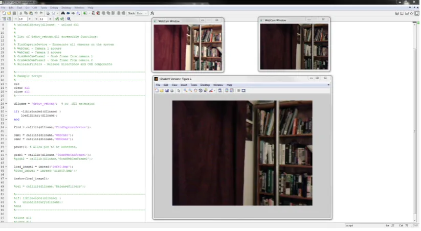
6.3.1 Access Through MATLAB . . . 53
6.3.2 Access Through C . . . 54
6.4 Scene Capture and Stereo Processing . . . 55
6.4.1 Object Position and Scene Type . . . 56
CONTENTS x
6.4.3 Scene 2 - The Living Room . . . 57
6.4.4 Webcam Mounting . . . 58
6.4.5 Webcam Calibration . . . 58
6.4.6 Image Rectification . . . 61
6.4.7 Stereo Processing . . . 63
6.5 Chapter Summary . . . 64
Chapter 7 Results and Discussion 65 7.1 Chapter Overview . . . 65
7.2 Image Capture Platform Operation . . . 65
7.2.1 Enumeration of Devices . . . 66
7.2.2 Access and Operation of Devices . . . 66
7.2.3 Image Capture and Image Output . . . 68
7.2.4 Edge Detection Processing . . . 69
7.3 Image Capture Library Operation . . . 70
7.3.1 Access Through MATLAB . . . 70
7.3.2 Access Through C . . . 71
7.4 Scene Capture and Stereo Processing . . . 71
7.4.1 Webcam Comparison and Image Resolution . . . 72
7.4.2 Object Position and Scene Type . . . 73
CONTENTS xi
7.4.4 Webcam Calibration and Image Rectification Effects on Stereo
Processing . . . 77
7.5 Chapter Summary . . . 78
Chapter 8 Conclusions 79 8.1 Chapter Overview . . . 79
8.2 Achievement of Project Objectives . . . 79
8.3 Shortcomings and Possible Improvements . . . 82
8.4 Further Work . . . 83
8.5 Final Conclusion . . . 83
References 84 Appendix A Project Specification 88 Appendix B Project Timeline 91 Appendix C Source Code Listings 92 C.1 Source - dshow webcam.c . . . 93
C.2 Source - calldll.c . . . 133
C.3 Source - directshow webcam.c . . . 150
C.4 Script - matdll.m . . . 153
C.5 Script - runlrc905640r150.m . . . 154
CONTENTS xii
C.7 Script - runlrc905640nr150.m . . . 156
C.8 Script - runlrc905640nr.m . . . 157
C.9 Script - runbsc905640r150.m . . . 158
C.10 Script - runbsc905640r.m . . . 159
C.11 Script - runbsc905640nr150.m . . . 160
C.12 Script - runbsc905640nr.m . . . 161
C.13 Script - runbsc200640r.m . . . 162
C.14 Script - runbsc200640nr.m . . . 163
C.15 Script - runbsc200320r.m . . . 164
C.16 Script - runbsc200320nr.m . . . 165
List of Figures
2.1 Overview of a stereo vision system . . . 6
2.2 Pinhole camera model . . . 7
3.1 Overview of the system operation . . . 19
5.1 Pins attached to filter of the C905 webcam . . . 37
5.2 Overview of the Microsoft DirectShow operation . . . 38
5.3 Final image capture platform GUI . . . 40
6.1 Testing of pixel threshold for edge detection processing . . . 53
6.2 Testing of image capture library in MATLAB . . . 54
6.3 Testing of image capture library in C . . . 55
6.4 Book shelf scene with points of interest for stereo processing . . . 57
6.5 Living room scene with points of interest for stereo processing . . . 58
6.6 Webcam mounting configuration with a 50 mm baseline value . . . 59
LIST OF FIGURES xiv
6.8 Manual selection of checkerboard corners . . . 60
6.9 Lens distortion of the C200 webcam . . . 61
6.10 Stereo calibration result and extrinsic representation . . . 62
6.11 Image pair after removal of distortion and rectification applied . . . 62
6.12 Test of the Middelbury benchmark image pair with the Dense Stereo algorithm . . . 63
7.1 Bookshelf scene - C200 webcam at 320 x 240 pixels, non-rectified and rectified . . . 73
7.2 Bookshelf scene - C905 webcam at 640 x 480 pixels, non-rectified and rectified . . . 74
7.3 Living Room scene captured with the C905 webcam at 640 x 480 pixels, non-rectified and rectified . . . 74
7.4 Bookshelf scene - C200 webcam at 640 x 480 pixels, non-rectified and rectified . . . 75
7.5 Living Room scene - C905 webcam at 640 x 480 pixels, non-rectified and rectified and with a baseline of 150 mm . . . 76
List of Tables
3.1 Hazard Likelihood . . . 26
3.2 Hazard Consequence . . . 26
3.3 Risk Matrix . . . 26
3.4 Risk Analysis . . . 27
4.1 Test Platform 1: Properties . . . 31
4.2 Test Platform 2: Properties . . . 31
4.3 Test Platform 3: Properties . . . 32
4.4 C200 Webcam Properties . . . 32
4.5 C905 Webcam Properties . . . 33
6.1 Image capture platform webcam configuration for testing . . . 52
6.2 Stereo processing configurations for experimentation . . . 64
7.1 Test Platform 1 and 3 access and operation results and configuration . . 67
LIST OF TABLES xvi
7.3 Frame rate for the three test platforms . . . 69
Glossary of Terms
API Application Programming Interface
CCD Charged Coupled Device
CMOS Complementary Metal Oxide Semiconductor
COM Component Object Model
CPU Central Processing Unit
DLL Dynamic Linked Library
EA Engineers Australia
FPGA Field-programmable Gate Array
GPU Graphical Processing Unit
GUI Graphical User Interface
HD High Definition
IDE Integrated Development Environment
JPEG Joint Photographic Experts Group
LED Light Emitting Diode
LIDAR Light Detection and Ranging
OS Operating System
OTS Off The Shelf
PCI Peripheral Component Interconnect
SDK Software Development Kit
USB Universal Serial Bus
UVC USB Video Class
VFW Video For Windows
V4L Video4Linux
Chapter 1
The Utilisation of Webcams for
Stereo Vision
Stereo vision research and development has been carried out for almost half a century.
It has been the objective of researchers to provide a system that is capable of robust,
precise and accurate stereo vision for a large range of applications. While the most
common applications for stereo vision have involved robotics and machine vision, new
applications have been emerging in remote machine access and personal entertainment.
Accessibility has long been a limitation in the filed of stereo vision research and
devel-opment, as the cost involved with purchasing professional image capture devices has not
been feasible. The requirement has existed for a low-cost image capture platform
ca-pable of simultaneous image capture that can be used for computer vision applications
including stereo and multiple camera vision processing.
A solution to the accessibility issue will be investigated that includes the
implementa-tion of low-cost and off-the-shelf consumer webcams. The consumer webcam has been
selected as it has evolved over the years to become a highly capable video and image
capture device.
Existing approaches in developing an image capture platform have been limited by
cap-1.1 Project Aim 2
ture simultaneously. The developer has usually had the task of creating the software
from scratch, as existing packages are either too expensive or are produced for a niche
application and for specific hardware.
By developing an image capture platform it will be possible to determine the suitability
of the webcam for high demanding tasks, such as stereo vision. This will involve the
investigation and application of calibration, image rectification and disparity mapping
processes for the analysis of stereo vision suitability.
Combining webcams with the increasingly powerful desktop personal computer may
provide the potential for a low-cost capture platform for research and development
ap-plications in the field of stereo vision. The requirement for a robust, accurate, economic
and accessible system still exists and this project suggests that a solution is achievable.
1.1
Project Aim
The project aims at providing a solution for the simultaneous operation and image
capture from consumer webcams and investigating the suitability of webcams for stereo
vision applications. The project will involve the creation of a software solution for an
image capture platform that can be used as a stand-alone application or implemented
into a library for use by other applications. It is also intended that the capture platform
will be used in further research projects.
The suitability of using webcams for stereo vision applications will be researched and
tested to identify any limitations that may exists. The research will not only cover
stereo processing, but will include calibration and image rectification techniques and
processes, that will be included in the testing stages for the project.
1.2
Project Objectives
1.3 Overview of the Dissertation Structure 3
• Research stereo and multiple camera vision systems including occlusion reduction and depth extraction techniques.
• Research the feasibility of operating two or more USB webcam devices
simulta-neously on a single personal computer.
• Design of a software access and control system for multiple webcam image acqui-sition and edge detection.
• Research calibration and stereo disparity processing techniques and the feasibility of applying them to the image acquisition system.
• Analyse captured image data for edge detection and surface processing accuracy.
• Design and implement image acquisition library into Dynamic-link library format for access by other applications.
Additional objectives will be commenced if time and resources permit:
• Investigate the feasibility of implementing the software system on multiple OS platforms.
• Extend application research into infrared cameras and game based controllers.
• Design of software functions for multiple webcam calibration and stereo disparity processing.
1.3
Overview of the Dissertation Structure
The dissertation is organised as follows:
• Chapter 1 - Provide an introduction for the project and detail on the aim and objectives.
• Chapter 2- The existing literature and approaches will be reviewed to determine the projects feasibility and methodology. Basic concepts related to the project
1.3 Overview of the Dissertation Structure 4
• Chapter 3 - The methodology and approaches for the project will covered and provide an overview of how the project will be completed. Risk assessment and
sustainable practices will be detailed in relation to the project.
• Chapter 4- The selection of the necessary hardware for both the webcams and computer testing platforms will detailed.
• Chapter 5- The overall development stage for the image capture platform and
library will be outlined. The development stage will provide information on key
areas that are critical for the successful operation of the software.
• Chapter 6 - The processes involved with testing the image capture platform,
library and stereo vision processing will be discussed.
• Chapter 7- The chapter will discuss the findings and results from testing stage.
Chapter 2
Literature Review
2.1
Chapter Overview
Stereo vision systems have been research and developed for over 40 years (Narasimha
2010). Early research was limited however to the technology and computing power at
the time. This led to much research being carried out with low resolution random dot
stereograms (Julesz 1964, p. 357). Current computer systems and capture devices have
the potential for high resolution and real-time stereo vision processing for applications
requiring 3-dimensional environment information.
This chapter investigates and reviews the existing literature and approaches for
devel-oping a computer based stereo vision system. This includes investigating the feasibility
of implementing OTS webcams into a stereo vision system.
2.2
Computer Based Stereo Vision
Single image and video capture devices obtain two-dimensional images, thus it is
nec-essary to recover the third dimension from multiple images captured of the same scene
from two or more devices (Mubarak 1997, p. 111). Stereo vision is able to achieve the
2.2 Computer Based Stereo Vision 6
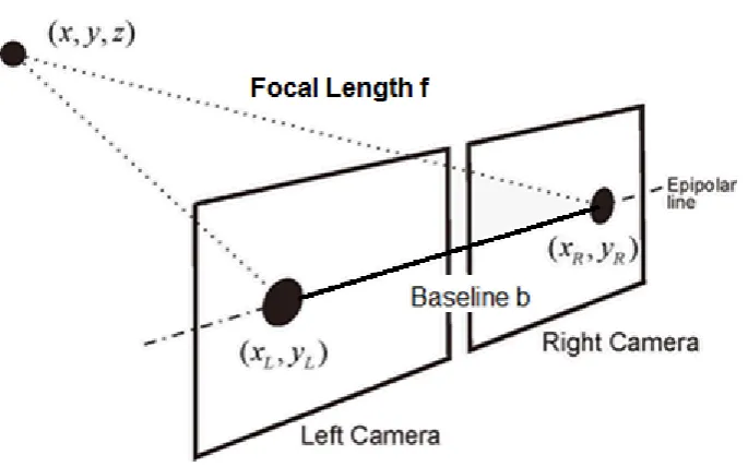
Figure 2.1: Overview of a stereo vision system
The basic stereo configuration is detailed in Figure 2.1, which depicts the relationship
of the two camera system with the object of interest.
Where:
• Image Matrix =xL, xR
• Disparity (D) =xLxR=bf /Z
• Depth (Z) =bf /(xLxR)
Numerous stereo algorithms have been developed, evaluated and documented over the
years (Scharstein & Szeliski 2001) that continuously aim at retrieving accurate and
reliable 3-Dimensional data. Common stereo algorithms including Banard’s Stereo
(Mubarak 1997, p. 117), Marr-Poggio cooperative stereo (Forsyth & Ponce 2002,
p. 330) and the Horn and Ikeuchi algorithms (Forsyth & Ponce 2002) are widely
documented in computer vision literature.
Each algorithm performs differently depending on the image data, for example it was
found (Forsyth & Ponce 2002) that the Marr-Poggio approach works well on random
dot stereograms, but not on natural images. A gross simplification is that these
2.2 Computer Based Stereo Vision 7
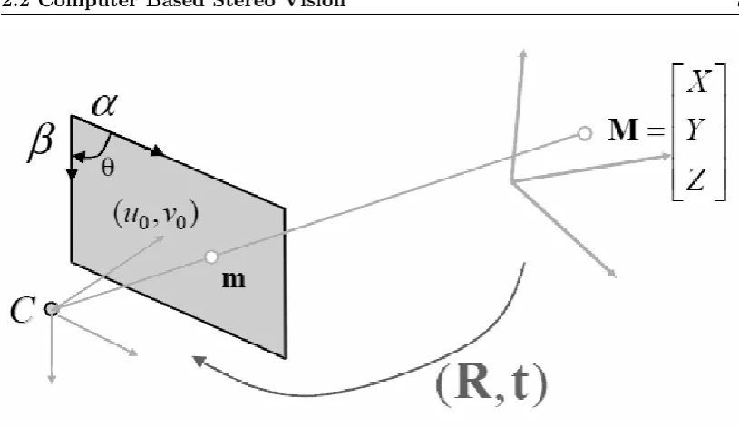
Figure 2.2: Pinhole camera model
of uniqueness between the left and right images.
2.2.1 Camera Calibration and Image Rectification
Camera calibration is an important process for the retrieval of accurate 3-Dimensional
data from images (Davies 2004). The function of camera calibration in a stereo vision
system is to retrieve the intrinsic and extrinsic parameters of the each individual camera
and then the combined camera system. Intrinsic parameters are used to model the
imaging process, and extrinsic parameters are used to model the cameras location in
its environment (House & Nickels 2006).
Zhang (2000) describes the common conventions used for the describing the
calibra-tion approach by using the pinhole camera model in Figure 2.2, which describes the
relationship between the image plane and the coordinates of a 3-Dimensional point
where:
• Denoting a 2D point as a vectorm= [u, v]T.
2.2 Computer Based Stereo Vision 8
• The augmented vector is defined by ˜x and an additional 1 is added to the last vector elementm= [u, v,1]T andM = [X, Y, Z,1]T.
• When an image is taken, the 3D pointM, denoted by m is formed by an optical
ray fromMintersecting the image plane and passing through the optical center of
the cameraC.
• The three pointsM,mand Care collinear.
The relationship between the real world 3D pointMand the captured projection point
mis determined by:
sm˜ =A[R, t] ˜M =PM˜ (2.1)
A=
α γ u0
0 β−e v0
0 0 1
.
P =A[R, t] (2.2)
Where:
• sis an arbitrary scale factor.
• [R, t]is the extrinsic parameters, which represent the rotation and translation relating the world coordinate system to the camera coordinate system.
• A is called the camera intrinsic matrix with (u0, v0) the coordinates of the
principal point.
• α andβ are the scale factors with regards to the imageuand vaxes,
2.2 Computer Based Stereo Vision 9
The resulting 3 X 4 matrixPis defined as the camera projection matrix. This matrix
combines both the intrinsic and extrinsic properties that can be applied to rectification
of the captured image pairs.
Medioni and Kang (2004) describes a popular technique that consist of using a
checker-board pattern for calibration. The steps involved are:
• Detecting the corners of the checker pattern in each captured image.
• Estimating the Camera projection matrixP.
• Recovering the intrinsic and extrinsic parametersA,Rand tfrom the projection matrixP.
Camera calibration is necessary before the image pairs can be rectified, as the
cali-bration process determines the image transformational information (R. Guerchouche
2008). The rectification process provides corrections for radial lens distortion, the
prin-cipal point and focal lengths. Guerchouche (2008) reports that rectification errors are
usually a result of poor placement of the calibrating image pattern, which leads to
blurred images and reduces edge or corner detection accuracy.
2.2.2 Occlusion Reduction
Stereo vision systems are usually developed with two cameras that create a stereo pair
of images. This has limitations due to occlusion where pixels from one image do not
have a match in the correlating stereo pair image (Zitnick & Kanade 1999, p. 675).
This can be caused by foreground objects blocking background objects in a scene. It
has been documented (Zitnick & Kanade 1999) that a typical approach to deal with
occlusion is bidirectional matching that uses disparity mapping interpolation to improve
accuracy.
Research has also been carried out into other occlusion reducing methods. It has been
reported (Chen & Davis 2000) that limited success was achieved through varying the
2.3 Current Computer Based Stereo Vision Systems 10
of the system. Using trinocular vision, where three cameras are used has been shown to
achieve good results. Asensio and Montano report that this method has the advantage
of improved accuracy with stereo matching; however it requires greater resources to
achieve.
2.3
Current Computer Based Stereo Vision Systems
Current stereo vision systems tend to be designed around a specific niche application
with a strong emphasis on machine vision. This results in a system that has software
and hardware dependencies unique to the niche application. Attempts to create user
friendly and accessible GUI’s or software packages still tend to be bounded to a single
OS platform being either Windows or Linux with no cross compatibility (Castejon
2009).
Other alternatives including the OpenCV library only provide C and C++ libraries for
stereo vision systems (Bradski & Kaehler 2008). MATLAB has also been used as a
software interfacing package; however this results in a dependency to MATLAB and
does not provide a stand-alone user interface.
It has been identified that the necessity for a system to be low-cost is usually
overshad-owed by the requirement of accuracy and robustness. It has been reported (Murphy,
Lindquist, Rynning, Cecil, Leavitt & Chang 2007) that this has resulted in a cost
pro-hibitive technology and limits access for future research and development. The USB
webcam can provide a platform that can capture Full HD resolution video at 30 frames
per second. The USB webcam also provides this functionality at a cost $10 - $150 per
unit, which is an attractive option when compared to existing systems such as LIDAR
that can cost $7,000 - $20,000 (Murphy et al. 2007, p. 333). FPGA devices provide
another alternative, but low cost configurations require development, interfacing and
2.4 Operation of Multiple Webcams 11
2.4
Operation of Multiple Webcams
It is necessary to operate two or more webcams simultaneously and to capture video
frame data for further processing. In order to achieve this objective it will be necessary
to determine the feasibility of webcam operation in relation to both the hardware and
software components.
2.4.1 USB Interface Capabilities
The use of two or more webcam devices places increased strain on transfer methods
between the webcams and computer system. All current webcams and computer
sys-tems provide USB connectivity of version 2.0 to meet the bandwidth requirement of
streaming video data.
USB 2.0 provides suitable transfer speeds of 480 Mbps (Axelson 2009, p. 12), with the
release of USB 3.0 it is likely that hardware manufactures will start adopting the newer
standard in both webcams and computer systems that can provide transfers of up to 5
Gbps (Axelson 2009, p. 13).
2.4.2 Application Programming Interface
The interface between the webcam device drivers and the OS requires compatibility
with new and old webcam devices while also being able to stream from two or more
webcams. This project will involve the development of an image capture platform
capable of running on Microsoft Windows OS’s, however non-Windows OS’s will be
researched for the potential of future work.
2.4.3 Microsoft Windows API’s
Microsoft has developed many multimedia APIs to operate on their Windows based
OSs. The first notable API was Video For Windows (VFW), which was provided
2.4 Operation of Multiple Webcams 12
format and device support (Microsoft 2011a) due to it’s early development and release. Subsequently VFW has been superseded by the DirectShow API (Microsoft 2011b).
The Directshow API was released in 1996 under the name ActiveMovie, however it
was renamed to DirectShow in 1998 to distinguish it’s link with the DirectX API.
DirectShow has had many revisions since release with the notable inclusion of the
Video Mixing Renderer (VMR) filter (Microsoft 2011a). The VMR allows the mixing of multiple video sources into a single video stream.
DirectShow provides flexibility and high quality capture when working with
multime-dia streams (Microsoft 2011a). DirectShow applies filters for the control of capture devices. Multiple filters are able to be accessed simultaneously and are managed by
the DirectShow filtergraph. This capability will allow multiple webcams to operate
simultaneously.
DirectShow is still supported in the latest Windows OS - Windows 7, however it will be
superseded by the Microsoft Media Foundation API. Media Foundation was released
in 2007 with the Windows Vista OS and is currently supported alongside DirectShow
(Microsoft 2011c). Media Foundation will include support for emerging high definition devices and formats.
The support and documentation for both VFW and Media Foundation is limited due
VFW being superseded and the relatively short period that Media Foundation has
been in use. DirectShow provides the compatibility, functionality and support that the
alternative API’s lack.
2.4.4 Linux and Apple API’s
Non Microsoft OS’s have a substantially smaller market share with Microsoft controlling
over 90% of the market (Net Market Share 2011). Both Linux and Apple Mac OS
distributions also include some form of multimedia API for video capture.
Linux OS distributions can access and manipulate multimedia streams with the Video4Linux
op-2.5 Infrared Based Game Controllers for Stereo Vision Systems 13
eration of multiple devices and supporting common image and video formats (LinuxTV
2009).
A limitation of V4L is the small number of supported hardware devices, as some
man-ufactures do not provide device drivers for Linux. To provide improved device support
Linux provides a default USB Video Class (UVC) driver (Ubuntu 2011).
Apple provides the QuickTime API for both Windows and Mac OS. The API
pro-vides over 2500 multimedia functions for manipulating and controlling video and audio
data (Appple 2011). The Quicktime API supports numerous languages including C,
C++, C#, Java and supports Component Object Model (COM) and .Net frameworks.
Quicktime allows multiple media sources to operate simultaneously and to allow image
capture.
2.5
Infrared Based Game Controllers for Stereo Vision
Systems
The method for controlling actions and movement inside a video game environment has
changed in recent years with the release of the Nintendo Wii gaming console in 2006
and with the Xbox Kinect gaming controller in 2010. The controllers provide a wireless
and infrared method of object tracking. Both the Wii and Xbox controllers provide a
feasible alternatives for stereo vision systems.
2.5.1 Nintendo Wii
The Wii controller contains conventional buttons along with an infrared camera. A
sen-sor bar containing two clusters of infrared LEDs is positioned near the output display.
The controller works by detecting the two cluster points and calculates the relative
position and direction of movement of the controller with respect to the display (Hay,
Newman & Harle 2008).
2.6 Chapter Summary 14
combined with an infrared filter capable of sensing up to four infrared points at a speed
of 100 Hz (Cuypers n.d.).
(Lee 2008) reports that it is feasible to create an inexpensive stereo vision system with
Wii controllers, while using more then two controllers may reduce occlusion issues.
Existing research has also concluded that a level of precision under 3 mm is possible
with a calibrated Wii-based system (Cuypers n.d.).
2.5.2 Xbox Kinect
The Kinect controller is gaining popularity in the development community, with the
official support and release of a software development kit by Microsoft.
The operation of the kinect controller involves an infrared projector and camera
in-corporated into the same piece of hardware. The infrared projector projects a known,
near-random pattern of infrared dots onto its field of view. The dots are captured by
the infrared camera that is offset by 25 mm from the projector on its epipolar axis.
The depth of an object is determined by the level of dot disparity between the known
projection pattern and the dot pattern captured by the camera (Ball & Taschuk 2011).
The Kinect controller provides advantages over existing stereo vision systems, as it can
handle ambient lighting condition as it does not register light in the visible spectrum
(Carmody 2010) and (Ball & Taschuk 2011) found that it is feasible to develop a vision
system with a single capture device capable of depth estimation.
2.6
Chapter Summary
From the conducted research it has been determined that the requirement does exist
for an accessible and low cost image capture system implemented from OTS hardware,
capable of collecting image data for stereo processing.
There has been a wide range of research into the field of stereo vision; however a large
Cam-2.6 Chapter Summary 15
era calibration and image rectification has been researched thoroughly an its importance
appreciated for the successful implementation of a stereo vision system capable of depth
estimation.
The use of infrared gaming controllers for an economical and alternative stereo vision
system is feasible and development is relatively new and progressing rapidly.
From the determined feasibility this project aims at implementing multiple USB
web-cams via an API into an image capture platform. The capture platform will provide the
capability of simultaneous image capture that will be used for further stereo processing
Chapter 3
Methodology for Software
Development and Stereo Vision
Evaluation
3.1
Chapter Overview
This chapter covers the methodology and approach taken for the development of the
multiple camera platform and stereo vision evaluation. This chapter also provides
information on the risks and consequential effects involved with the research and
de-velopment.
3.1.1 Project Methodology
To determine the methodology of the project it was necessary to develop an
under-standing of how the objectives would be achieved and therefore a logical breakdown of
the main tasks.
The tasks involve creating an image capture platform and library for webcams that can
3.1 Chapter Overview 17
further stereo processing for depth estimation. For this to be achieved it is important
that the correct interactions between the systems software and hardware layers are
implemented.
The system will require at least two webcams for stereo vision processing. The webcams
will require a physical mounting, so that they share a common scene of interest during
the image capture process. The webcams need to be interfaced with the desktop system,
so that the video streams can be accessed and image data retrieved from video frames.
A software platform with an intuitive GUI will need to be developed to allow the user
to operate the webcams and capture image data for later processing. The GUI will
need to provide the user with enough control to add or remove webcams and to adjust
the webcam properties.
Calibration of the webcams will be required to correct any variation in physical
orienta-tion and locaorienta-tion. This process will have to retrieve the cameras intrinsic and extrinsic
parameters for accurate stereo processing.
A software process will need to be applied that is able to perform image rectification
and edge detection. This is necessary to align the image pair planes and to identify
points of correlation between the images, which will result in a higher level of stereo
vision processing accuracy.
The next software process will apply the stereo processing that will result in disparity
mapping. The generated disparity maps will be evaluated for accuracy and suitability
to real world applications.
The development of a webcam access software library will be carried out for testing in
other programming applications or existing software packages. The outlined
method-ology requires that all the necessary tools, such as IDEs have been configured and that
3.2 Task Breakdown 18
3.2
Task Breakdown
The project methodology can be refined into eight major tasks:
1. Stereo webcam mounting
2. Webcam Interfacing in both hardware and software
3. Development of the multiple camera access platform
4. Software library development for webcam access
5. Webcam image capture
6. Webcam calibration to correct intrinsic and extrinsic parameters
7. Image pair rectification and edge detection
8. Stereo processing and disparity mapping
These tasks are identified as being key milestones for development and as and indication
of the projects progression.
3.3
System Operation
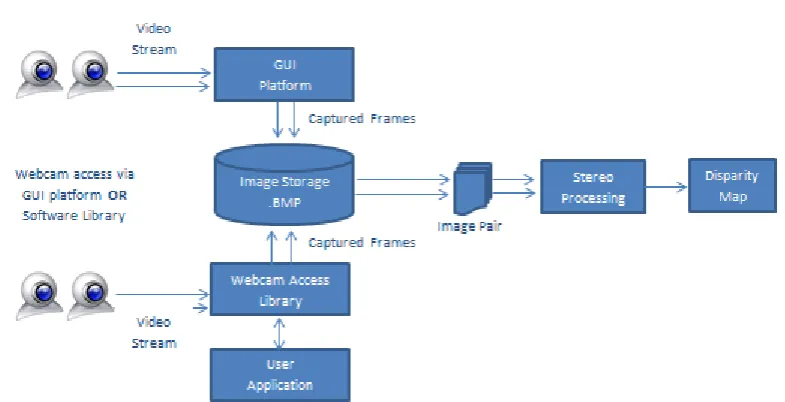
The overall system in Figure 3.1 consists of two key components:
1. Webcam access and capture through the GUI platform or software library
2. Stereo processing of captured image pair data.
The operation of the system is reflected in the developmental task breakdown and how
3.4 Task Analysis 19
Figure 3.1: Overview of the system operation
3.4
Task Analysis
The methodology for the eight major tasks defined for this project will be analysed to
determine the approach to be taken and the resources required.
3.4.1 Stereo Webcam Mounting
The webcams will require mounting during the image capture and stereo processing
stages of the project. The selected mount must provide a solid foundation for the
webcams to reduce any unwanted webcam movement or vibrations. The mount must
also accept different webcam models and configurations. The mount will be situated
in an office environment and will also be limited to the physical space available.
Resources Required:
3.4 Task Analysis 20
3.4.2 Webcam Interfacing in Both Hardware and Software
The hardware interfacing for the webcam should be straight forward as completed
research has found that the USB interface is common amongst all webcam and
mother-board manufactures. The software interfacing will be more challenging, as code needs
to be developed that will allow the webcam to interact with the OS, image capture
plat-form and library. The software interface will have to include a suitable API that allows
multiple webcams to operate simultaneously on a single desktop computer system.
Resources Required:
• Webcams with USB connectivity.
• Desktop computer system(s) for testing that include USB connectivity.
• API for software interfacing.
3.4.3 Development of the Multiple Camera Access Platform
The image capture platform will require a functional and easy to use GUI for user
interaction. This will involve writing a Windows application that provides functionality
for webcam selection, playback, edge detection and image capture. The user should be
able to control the operation of all the functionality components, which would provide
a better user experience. The platform should allow access of at least three webcams
for image capture and streaming. This will be a capability that has not been found
in other webcam applications that limit the number of webcams and image capture to
only one or two devices.
Resources Required:
• Webcams
• Selection of programming language.
3.4 Task Analysis 21
3.4.4 Webcam Image Capture
This will also involve the creation of software that is capable of capturing the video
frames from the streaming webcam video. The captured images should be able to be
stored in a common image format that is supported by most applications. The capture
will need to be simultaneous with little time separating each webcam capture.
Resources Required:
• Webcams
• Selection of programming language.
• IDE for software development.
3.4.5 Webcam Calibration for the Correction of Intrinsic and
Extrin-sic Parameters
A calibration process will need to be acquired that can be applied to the captured
images from the image capture platform or library. The calibration must be able to
determine the intrinsic and extrinsic parameters of the webcams and environment. The
calibration data must be able to be collected and stored for further processing including
image rectification.
Resources Required:
• Existing calibration software package.
3.4.6 Image Pair Rectification and Edge Detection
The image rectification process must operate similarly to the calibration process, where
the process can be applied to the captured images from the platform. This will involve
writing a software process, modifying provided code by Dr John Leis or using an
3.4 Task Analysis 22
Resources Required:
• Existing software package capable of handling imported images and calibration
data.
3.4.7 Stereo Processing and Disparity Mapping
The suitability of using webcams for image capture and stereo vision is a major objective
in the project. The approach for applying stereo processing to the captured images must
be robust and accurate. Since numerous stereo algorithms exist it will be necessary to
research and select one capable of handling the image format and selected scene type.
It may be necessary to save captured images in a format that can be accessed by the
stereo vision processing package.
Resources Required:
• Existing Stereo Vision Processing software package.
• Suitable scene for testing.
3.4.8 Software Library Development for Webcam Access
The image capture library development will require a programming approach that
includes the required DLL commands. The DLL format will need researching before
development can begin. The Library should be able to be tested in both a third party
application such as MATLAB; and through a developed program. The library will
provide similar functionality to the image capture platform.
Resources Required:
• Selection of programming language.
3.5 Consequential Effects 23
3.5
Consequential Effects
The possible consequences of introducing a new system into the public have been
in-vestigated to ensure the impact is sustainable, safe and ethical (USQ 2011).
3.5.1 Sustainability
EA has provided guidelines for evaluating the sustainability on the environmental,
social and economical systems over its full life cycle (Engineers Australia 2011b). The proposed stereo vision system will have a minimal impact during its lifecycle.
The manufacture of the device and the energy consumption does contribute to the
usage of energy and materials developed through non-renewable processes. These issues
involving the manufacturers processes are outside of the scope of this project.
3.5.2 Safety
The system will consist of OTS webcams and desktop computer systems that must
meet the required Australian Safety Standards.
3.5.3 Ethical Dimensions
EA provides a code of ethics to be related to engineering practices (Engineers Australia
2011a). The code of ethics covers integrity, competence, leadership and sustainability. In undertaking this project it is important to incorporate the code of ethics in all
areas, to ensure that the final outcome of the project will reflect the best interests of
3.6 Risk Assessment 24
3.6
Risk Assessment
The risks and possible hazards associated with this project are similar to those involved
in any IT environment. It is important to identify and reduce the likelihood of risk
associated with the project and its use by both the operator and future users.
3.6.1 Risk During the Execution of the Project
The following hazards have been identified as those possibly encountered during the
execution of the project:
1. Occupational Overuse Syndrome:
• Evaluation - These types of injuries occur after prolonged use of computer peripherals including the mouse and keyboard. Injuries include tendonitis
and carpel tunnel syndrome.
• Control Take regular breaks from prolonged usage. Make sure breaks include
standing and walking for several minutes.
2. Lighting:
• Evaluation - Poor lighting including glare can cause eye strain and headaches
for the operator.
• Control Correctly position monitors so they are adjacent to windows. Close
blinds or curtains if necessary and possibly use a screen filter.
3. Stress:
• Evaluation - Long hours and insufficient breaks can cause stress to the op-erator and therefore increase the likelihood of other conditions.
• Control Healthy diet, exercise and break up large tasks into smaller and more manageable tasks and take regular break.
3.6 Risk Assessment 25
• Evaluation - Radiation from electrical devices such as wireless routers pro-duce low levels of radiation and operate without risk unless the device has
become damaged.
• Control Do not used damaged electrical devices, place any wireless emitters
away from users or disable when not in use.
5. Noise:
• Evaluation - Office equipment produces low levels of noise that is harmful to human hearing; however damaged equipment may increase the level of noise
and should be investigated.
• Control Correct placement of noise producing devices, so there is a physical
distance between the user and device.
6. Electrocution:
• Evaluation - All mains power equipment in commercial use is to be tested and tagged to reduce the use of damage equipment. It is possible that
damage equipment can be used, which
• can cause serious risk to the user. Control Avoid using food or drinks around electrical equipment, never dismantle equipment unless qualified and do not
place power chords in areas of high traffic.
7. Heavy Lifting:
• Evaluation Some computer systems and monitors can be heavy and cause injuries.
• Control Follow correct lifting instructions provided by manufactures, always lift with a straight back and if necessary get assistance from others.
3.6.2 Risk Beyond the Completion of the Project
The same hazards found during the execution of the project apply to the future users
3.6 Risk Assessment 26
Level Code Description
1 Rare Event may occur only in exceptional circumstances
2 Unlikely The event may occur at some time, once in 10 years
3 Moderate The event should occur at some time, once in 3 years
4 Likely The event will probably occur in most circumstances, once
a year
5 Almost Certain The event is expected to occur in most circumstances, many
times a month
Table 3.1: Hazard Likelihood
Level Code Description
1 Insignificant First Aid and/or Minor Equipment Damage
2 Minor First Aid and/or Major Destruction of Equipment
3 Moderate Moderate Injury or Illness requiring examination
4 Major Major illness or temporary disability requiring
hospitalisa-tion
5 Catastrophic Death or permanent disability
Table 3.2: Hazard Consequence
Consequence 5, Almost Certain 4, Likely 3, Moderate 2, Unlikely 1, Rare
5, Catastrophic 25 24 23 22 18
4, Major 21 20 17 16 11
3, Moderate 19 15 14 10 7
2, Minor 13 12 9 6 5
1, Insignificant 8 4 3 2 1
3.7 Research Timeline 27
Hazard Likelihood Consequence Rating
Occupational Overuse Syndrome 3 3 14
Lighting 4 1 4
Stress 4 2 12
Radiation 1 2 6
Noise 4 1 4
Electrocution 2 5 22
Heavy Lifting 4 3 15
Table 3.4: Risk Analysis
3.6.3 Risk Summary
Overall the project will involve a low to medium level of risk. It is important to be
aware of the risks and take steps to reduce any consequences associated with them.
3.7
Research Timeline
The project timeline outlining the managment of tasks and achievement of milestones
is located in Appendix B.
3.8
Chapter Summary
The methodology and approaches for the major project tasks have been discussed in
this chapter. The task analysis outcomes will be implemented throughout the projects
progression.
The size and background of this project results in a low risk and sustainable outcome.
There are a small amount of hardware and software resources required, however most
Chapter 4
Test Platform and Webcam
Selection
4.1
Chapter Overview
This chapter provides information on the hardware selection criteria for the desktop
test platform and webcam selection. The selection of webcams and the test platform
is important, as it is a project requirement to utilise low-cost and OTS hardware for
the test PC and webcams.
4.2
Test platform Requirements
It is an important requirement that the image capture platform and stereo processing
can be operated on a commonly found desktop PC. The term common referring to a
desktop system of approximately five years of age. This is necessary to allow a greater
4.3 Webcam Requirements 29
4.2.1 USB Connectivity and Interfacing Requirements
The test platforms will require at least two available USB 2.0 ports for webcam
connec-tion. Two ports will be required for testing the stereo abilities of the captured image
pairs, while up to five ports will be required when testing the webcam enumeration and
detection process.
The USB 2.0 standard was released in 2000 and provides transfer speeds of 480 Mbit/s,
which is necessary for simultaneous video streams and image capture.
4.2.2 Processor Configuration
The video streaming, image capture and stereo processing will all be handled by the
system CPU. There is no utilisation of multi core processors during testing, which will
reflect the capabilities of some older desktop computers.
CPU’s manufactured by both Intel and AMD will be selected, as each processor provides
a different architectural design and features.
4.2.3 Operating System
Testing will be based on the Microsoft Windows OS. This will also increase the
acces-sibility of the software. The image capture platform has been designed to operate on
the Microsoft Windows XP, and Windows 7 OS’s in both 32 and 64 bit configurations.
Other OS exists from alternative manufactures, however Microsoft has the largest OS
market share, which results in a high level of accessability.
4.3
Webcam Requirements
The most important requirement in selecting webcams for this project is the unit price.
4.3 Webcam Requirements 30
consumer webcams for operation.
Considerations of less importance include the webcam mounting and USB cable length.
4.3.1 Webcam Costs
Commercially available webcam products are priced between $10 - $150 depending on
certain features and manufacture. It is therefore necessary that the user can install an
operate webcams that have been selected from the low end of the price spectrum.
4.3.2 Webcam Compatibility
There are two important areas to investigate for webcam compatibility:
• The software layer
• The hardware layer
On the software layer, Webcams interface with the OS through device specific drivers
and an API. Ensuring that a high level of compatibility exists has been covered by using
the Microsoft Windows OS and the Microsoft Directshow API, which is discussed in
Chapter 5.
The physical connection on almost all webcams is via the USB 2.0 interface. This
provides a capable interfacing technique as discussed in Section 4.2.1.
4.3.3 Webcam Build Quality and Properties
Webcam construction and build quality varies amongst manufacturers, webcam models
and even between two identical webcams. The lower cost webcams commonly utilise a
CMOS based image sensor and plastic optics, where as the more expensive webcams
4.4 Selected Test Platforms 31
These differences in construction will be analysed and evaluated for image quality and
the affects had on stereo processing.
4.4
Selected Test Platforms
Three test platforms were selected for the testing of the image capture platform and
software library, while a single system was selected for the stereo processing. The
systems were selected based on there high level of accessibility and configuration. Test
Platform 2 will be used for testing the stereo processing, as it has the lowest system
performance out of the three platforms.
The system specifications for each system are detailed in Table 4.1, Table 4.2 and
Table 4.3.
Test Platform: 1
Operating System Windows 7, 64 bit
CPU Model Intel Q6600
CPU Speed Quad Core @ 2.4 GHz
Memory 4 Gb
USB Standard 2.0
Table 4.1: Test Platform 1: Properties
Test Platform: 2
Operating System Windows 7, 32 bit
CPU Model AMD 9650
CPU Speed Quad Core @ 2.3 GHz
Memory 2 Gb
USB Standard 2.0
Table 4.2: Test Platform 2: Properties
This selection of test platforms ensures a good representation of common desktop
4.5 Selected Webcams 32
Test Platform: 3
Operating System Windows XP, 32 bit
CPU Model Intel Q6600
CPU Speed Quad Core @ 2.4 GHz
Memory 4 Gb
[image:50.595.217.426.409.553.2]USB Standard 2.0
Table 4.3: Test Platform 3: Properties
4.5
Selected Webcams
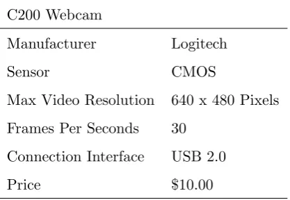
Two pairs of webcams were selected for operation and testing. These include the
Log-itech C200 and LogLog-itech C905. The webcams provide a good comparison of differently
priced and constructed webcams that are currently available on the market.
The webcam specifications are listed in Table 4.4 and Table 4.5.
C200 Webcam
Manufacturer Logitech
Sensor CMOS
Max Video Resolution 640 x 480 Pixels
Frames Per Seconds 30
Connection Interface USB 2.0
Price $10.00
Table 4.4: C200 Webcam Properties
4.6 Chapter Summary 33
C905 Webcam
Manufacturer Logitech
Sensor CCD
Max Video Resolution 1600 x 1200 Pixels
Frames Per Seconds 30
Connection Interface USB 2.0
Price $55.00
Table 4.5: C905 Webcam Properties
4.6
Chapter Summary
The hardware requirements and selection were discussed for the project. Suitable
desk-top computer test platforms were selected to provide a good range of hardware
config-urations during testing.
The requirements and selection of the webcams was completed, which consists of two
Chapter 5
Image Capture Platform and
Library Development
5.1
Chapter Overview
This chapter discusses the developmental process involved with the project.
Develop-ment involved two main tasks; the image capture platform GUI and the image capture
library. Each task required different knowledge and resources for successful execution.
The software requirements and selection for development are also discussed to provide
details on how they impacted on development process.
5.2
Software Requirements and Selection
The development tasks involved with the project focus on providing a software solution
for webcam access and image capture. This required the selection of:
• A suitable programming language
5.2 Software Requirements and Selection 35
• An Application Programming Interface
Each software requirement had to be solved based on, existing familiarity, functionality,
accessibility and time required for competent operation.
5.2.1 Programming Language
Both the image capture platform and library had to be programmed in a language
that could be compiled and operated on the Microsoft Windows OS. It also had to be
suitable for developing the DLL format library.
Other considerations for the selection of the programming language included speed of
execution and cross-platform portability. This project will not involve the
develop-ment of a software solution for non Windows based OS’s, however it maybe a task
in future projects. The potential for future project work was therefore an important
consideration when selecting a programming language.
The most suitable language that fulfilled the requirements was C. Other languages
would also be able to achieve the same outcome, however the C language has been in
use for almost 40 years and is well documented, supported, efficient and portable.
5.2.2 Integrated Development Environment
For a more efficient development approach it was necessary to select an IDE capable
of editing and compiling C source code.
After investigation and recommendation, the Wedit IDE was selected. Wedit is a simple
editor interface capable of syntax highlighting, which includes the lcc-win32 Compiler
system for Windows by Jacob Navia
The included library is capable of developing basic Windows and console applications.
This produced some limitations, as additional libraries had to be accessed and linked
5.2 Software Requirements and Selection 36
5.2.3 Application Programming Interface
The API is required to link the webcam device drivers and the OS together, so webcam
access can be achieved. The API must provide the abilities of operating multiple
webcams simultaneously and allow for image capture from the multiple video stream.
The Microsoft DirectShow API was selected for this task for the following reasons:
• DirectShow provides improved compatibility and support over VFW and Media Foundation for the selected test OS’s.
• The DirectShow architecture provides full manipulation and handling of
multi-media tasks.
• Source code examples developed by Dr John Leis have been provided that use the DirectShow API to access a single webcam and provide edge detection processing.
Specific requirements for the DirectShow API are a Windows XP - Service Pack 1
or Windows 7 OS. These OS’s include the Microsoft DirectX 9.0 or later API, that
incorporates the DirectShow API libraries.
5.2.4 Microsoft DirectShow Operation
DirectShow is able to handle multimedia by using two types of object classes:
• Filters which are the atomic entities and control the media devices attached to the system.
• Filtergraphs control multiple filters connected together.
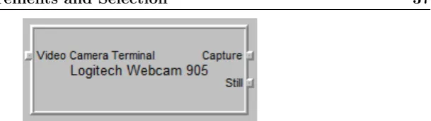
To access media from a device, the filter uses pins that can either receive an input
stream or send an output stream. The number of pins is determined by the device.
5.2 Software Requirements and Selection 37
Figure 5.1: Pins attached to filter of the C905 webcam
DirectShow is also based on the Component Object Model (COM), which allows
de-velopers to create binary based code components that are re-usable, can be created in
multiple languages and accessed by different applications.
COM components are created using Globally Unique Identifiers (GUID) or Universally
Unique Identifiers (UUID), which provide an identification method for the software
components. An an example of this is:
CoCreateInstance(&CLSID_FilterGraph, //Class ID for COM object
NULL,
CLSCTX_INPROC_SERVER,
&IID_IGraphBuilder, // Interface ID
(void **)&pGraphBuilder1); // Filter Pointer
pGraphBuilder1->AddFilter(pSrc1, L"Video Capture");
The code example creates a filtergraphpGraphBuilder1and attaches the filterpSrc1.
The filtergraph is encapsulated in the COM CLSID FilterGraph.
The capabilities of the DirectShow API can be broken into three areas, which are based
on the types of filter operation:
1. Capture of both audio and video from a live camera device, in this project
web-cams. This also includes the ability to open a file and treat it as if it were a live
multimedia source.
2. When a multimedia source has been selected and the video or audio stream
conver-5.3 Image Capture Platform Requirements 38
sion or splitting the media and sending it to multiple filters for further processing.
3. The third capability is rendering of the media to an output device. This includes
speakers, monitor display, writing to a disk or outputting to another device.
The three filter types and their relationship with the filtergraph and devices is shown
[image:56.595.114.526.233.472.2]in Figure 5.2.
Figure 5.2: Overview of the Microsoft DirectShow operation
5.3
Image Capture Platform Requirements
The image capture platform will provide the user with a stand-alone GUI package that
is easy to operate and provides a high level of functionality. The key requirements of
the platform include:
• Design of an easy to use GUI with webcam controls.
• List all the available webcams on the desktop system.
5.3 Image Capture Platform Requirements 39
• Provide the user with the option of selecting the webcams they require.
• Display a live video stream from the selected webcams.
• Apply real-time edge detection to the webcam video if selected by the user.
• Capture video frames from the webcam video streams and store them to disk in *.BMP format.
• Upon closing the image capture platform application close all DirectShow objects.
Each of the listed requirements must be addressed during the development stage of the
project to ensure that a suitable solution is achieved.
5.3.1 Review of Provided Code Example
An existing code example was provided by Dr John Leis of the University of
South-ern Queensland. The code allowed the user to access a single webcam and provided
playback controls and real-time edge detection to the video stream.
The code provided a working method for accessing a webcam through the DirectShow
API on a Windows based OS. Components of the code have been modified and included
into the development of the image capture platform.
5.3.2 GUI Layout
It is an important requirement that the user be able to easily work with and operate
the platform. This requires a user-friendly and intuitive GUI design that provides quick
access to user operated controls.
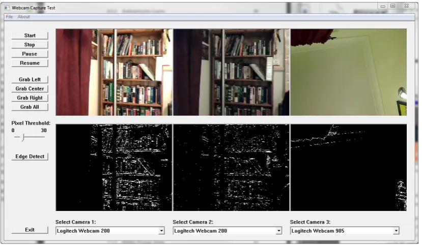
The overall layout for the platform is comprised of six video windows in a 2x3
con-figuration. Each window is 320 pixels wide and 240 pixels high. These dimensions
were used to conserve the amount of desktop space required during operation. The
5.3 Image Capture Platform Requirements 40
The bottom row displays the captured webcam video with the edge detection process
[image:58.595.114.529.135.379.2]applied. Figure 5.3 shows the final image capture platform GUI.
Figure 5.3: Final image capture platform GUI
The GUI is designed to operate up to three webcams simultaneously. It is possible to
operate more devices with the DirectShow API, however this limitation was decided
upon to conserve desktop space. Each video window is provided with a drop down
menu for the individual webcam selection from up to five available webcams.
The GUI provides the user with a selection of controls for the webcam playback, image
capture and edge detection function. These controls were implemented as Windows
buttons in the left hand side of the GUI by using theCreateWindowEx command. An
example of this is the stop button:
CreateWindowEx(BS_PUSHBUTTON,
"button", // window class name
"Stop",
WS_CHILD | WS_VISIBLE | BS_PUSHBUTTON,
20, 55, 100, 20,
hWnd, (HMENU)IDB_STOPBUTTON,
5.3 Image Capture Platform Requirements 41
The playback controls included Start, Stop, Pause and Resume. Playback buttons were
linked to the DirectShowpMediaControl1command when activated by the user. This
resulted in:
• pMediaControl1->Run() for Start and Resume controls.
• pMediaControl1->Pause()for the Pause control
• pMediaControl1->Stop() for the Stop control. DirectShow objects are also re-leased when the Stop control is selected
Image capture button controls were implemented into the GUI for each individual
webcam or a single control can be used to grab a simultaneous frame from all running
webcams. The operation behind the controls is detailed in Image Acquisition section
of this chapter.
The provided edge detection code can be operated by selecting the Edge Detection
button control option on the GUI. This enables or disables the edge detection
func-tionality of the platform. The operation behind the edge detection control is detailed
in Real-Time Edge Detection section of this chapter.
5.3.3 Enumeration and Selection of Available Webcams
It was necessary to find and enumerate all the available webcams attached to the
system when the platform was started. This allows the user to easily select the required
webcams for streaming or capture.
The FindCaptureDevice() function was developed for the process of enumerating all
available webcams. The enumeration of devices was achieved by using the
Direct-Show command; CreateClassEnumerator. The CreateClassEnumerator command
was defined for video devices by using the CLSID VideoInputDeviceCategory
com-mand, which returned a collection device monikers. A device moniker is a COM object
5.3 Image Capture Platform Requirements 42
The overall enumeration process operates in a loop structure, outputting the device
information into monikers and then assigning the moniker to a filter. In the simplified
section of code from the platform development below, the device monikerpMonikeris
binded to the filter objectpEnumSrc1:
while (pClassEnum->Next(1, &pMoniker, NULL) == S_OK)
pMoniker->BindToStorage(0, 0, &IID_IPropertyBag, (void **)&pPropBag);
pMoniker->BindToObject(0,0,&IID_IBaseFilter, (void**)&pEnumSrc1);
The filter object is then used for other operations including the rendering of the video to
screen and for configuring the webcam properties. These other operations are detailed
throughout this chapter.
5.3.4 Control of Webcam Properties
When the user selects a webcam from the drop down menu, they will have the option
to modify the webcams properties. These properties include:
• Webcam image format
• Video resolution
• Frames per second for video streaming
The webcam video resolution can be adjusted by the user, however the webcam video
windows are restricted to the dimensions, 320 pixels wide and 240 pixels high. This
results in a scaled video been shown in the GUI. The captured image size will be the
same as the user selected resolution.
The webcam properties are accessed by querying the pins attached to the device filter.
5.3 Image Capture Platform Requirements 43
// Enumerate pins from Capture filter.
pSrc1->EnumPins(&pEnum1);
pEnum1->Reset();
pEnum1->Next(1, &m_pCamOutPin1, NULL);
// Pin Properties.
hr = m_pCamOutPin1->QueryInterface(&IID_ISpecifyPropertyPages,
(void **)&pSpecPropPage1);
if (SUCCEEDED(hr))
{
// Code for Property Window
}
The code operates by enumerating the pins from the filter objectpSrc1 and assigning
the pin object to m pCamOutPin1, which is queried by the command:
IID ISpecifyPropertyPages.
The webcam property window is then displayed for user interaction.
The code developed for the configuration of webcam properties is included in the
InitWebCamCapture’x’()where ’x’denotes a webcam number from 1-3.
5.3.5 Simultaneous Webcam Access
The requirement to operate multiple webcams simultaneously resulted in the
develop-ment of three individual DirectShow filter graph managers that manage each of the
three webcam filters.
The main webcam access functions that define and manage the filters are:
5.3 Image Capture Platform Requirements 44
while calls are made from withi