Field simulation studies for a high temperature
superconducting synchronous generator with a
coreless rotor
K.S. Ship and J.K. Sykulski
Abstract: A series of 2D and 3D modelling investigations have been undertaken to evaluate and optimise magnetic field distributions in a high temperature superconducting synchronous generator with a coreless rotor. Such design studies are essential to determine if the required air-gap flux density is achievable and at the same time maintaining the total harmonic voltage content within desirable limits. Moreover, due to the anisotropic properties of the superconducting tapes, the presence of carefully designed flux diverters is required in order to reduce the magnetic field normal to the broad face of the tape. It is therefore necessary to model and optimise the shape and position of the flux diverters to minimise the undesirable magnetic field components. Since a 2D model does not take into account the effect of the end leakage flux, a 3D model was used to confirm the effectiveness of the design changes.
1 Introduction
The discovery of high temperature superconductivity (HTS) has created an opportunity to develop the next generation of power devices, including smaller and more efficient rotating electrical machines. In the case of synchronous generators, the replacement of the copper field winding with a superconducting tape promises to deliver: (i) a superior performance; (ii) a more compact design; (iii) a higher reliability; and (iv) easier operation[1]. The HTS coils are inherently more stable than low temperature superconduct-ing coils (which require liquid helium coolsuperconduct-ing), especially when operated in a liquid nitrogen environment. Recent advances in refrigeration systems have helped significantly in reducing the overall costs, thus making the technology more attractive. Moreover, the availability of high quality BSCCO-2223 tapes with improved strength and critical currents makes the design of the next generation of HTS generator technologically viable.
Building on the success of our previous design and construction of a 100 kVA HTS demonstrator synchronous generator with a magnetic iron core[2], which has proven the feasibility of HTS generation and established a number of key design principles, it is possible now to consider a HTS synchronous generator with a coreless rotor. However, in order to achieve a successful design, it is imperative to first conduct computational and simulation studies to predict the performance and identify critical performance issues. In particular, the severe nonlinearity and anisotropy of the BSCCO tapes necessitates very careful shaping of the local distribution of the magnetic field in the area of the HTS winding so that the undesirable field components are reduced and maintained at an acceptable level. This is a
crucial requirement which may decide the success or failure of the whole design since HTS tapes will simply not work if the normal component of the field is too high. Thus, the geometry and placement of the necessary flux diverters is of paramount importance [3]. This work reports on the 2D and 3D studies undertaken to arrive at an optimal magnetic design for further perusal.
2 Preliminary design
The machine is designed to utilise an existing conventional stator, which has 48 slots and a balanced two-pole, three-phase star-connected winding. The use of an existing stator lowers the costs but restricts our flexibility to control the voltage waveform; thus careful positioning and shaping of the flux diverters and HTS field winding become very important. These requirements are very different from the usual design criteria for a conventional generator. The target air-gap density of the coreless rotor design is around 0.5 T, whereas the flux density normal to the broad face of the tape must be kept as low as possible. The machine will probably operate using sub-cooled liquid nitrogen at 64 K (rather than 77 K); at this temperature (and by using the currently best available material properties) it is possible for the HTS tape to transport 130 A provided that the normal field is below 0.1 T[4]. The amount of iron used for the flux diverters must be kept to a minimum so that the total weight reduction compared with the existing cored design will be significant.
A preliminary model of the machine was based on our previous experience and the following constraints:
The distance from the HTS tape to the flux diverters is 0.5 mm and 1.5 mm respectively (top and bottom).
The flux diverters are longer than the coils by 4 mm on both sides.
The assembly of the HTS coils and flux diverters has to fit within the 140 mm radius.
The 0.5 and 1.5 mm gaps are introduced to avoid short-circuit contact and at the same time provide space (larger
The authors are with the School of Electronics and Computer Science, University of Southampton, Southampton SO17 1BJ, UK
rIEE, 2004
IEE Proceedingsonline no. 20041104 doi:10.1049/ip-smt:20041104
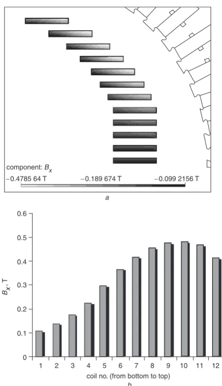
gap) for connecting conductors between HTS coils. The need to reduce the magnetic field component normal to the broad face of the tape, especially in the corner region, has already been explained. Finally, the large air-gap is needed to accommodate the supporting structure and thermal insula-tion. Moreover, for ease of manufacture, it was decided that the inner diameters of some HTS coils (and flux diverters) should be the same; thus the bottom five sets of coils and diverters were aligned with each other. Figure 1 shows the preliminary model with details of the applied constraints, as well as the distribution of the normal field in the HTS coils. This shape was obtained by fitting as many HTS coils as possible within the 140 mm radius. Each coil consists of 70 turns with each turn being of 0.5 mm width. Moreover, to demonstrate the importance of the effect, Fig. 2ashows the severity of the normal field in the superconducting coils in the absence of flux diverters; its effect is particularly apparent in the top region as shown in Fig. 2b.
A nonlinear analysis was performed throughout since saturation of the magnetic flux diverters was thought to be important. The symmetry of the machine is exploited by considering one-quarter of the area; regions are bounded by the rotor polar axis, the inter-polar axis and the back of the stator core: the rotor polar axis and back of the stator core were taken as flux lines withA¼0 and the rotor inter-polar axis had a zero normal derivative. The magnitudes of the sine components of odd-harmonic orders were extracted using Fourier series. This data can be used to construct the voltage waveforms and the resultant root-mean-square (RMS) value. It should be noted that due to symmetry the air-gap flux-density waveform contains no even harmonics. In the preliminary model, it was found that the total RMS harmonic voltage content was 1.59% and the air-gap flux density was estimated at 0.676 T. The component of the magnetic field normal to the broad face tape was unfortunately found to peak at 0.252 T (as shown in Fig. 1). This undesirable high normal field would signifi-cantly reduce the critical current and could cause the coils to loose superconducting properties.
3 Field optimisation
3.1
2D modelling
The preliminary investigation revealed that the main problem in the design is due to the normal component of
the magnetic field in the HTS coils. Through careful examination it was found that the high normal field was caused by the saturation of flux diverters especially between coils 7 to 12 which was shown in Fig. 2b. In order to minimise this effect, the amount of iron could be increased in the identified areas. Therefore, one HTS coil was removed leaving 11 coils as shown in Fig. 4a. Figure 4 also shows the harmonic content of the voltage waveform and the distribution of the normal field after the thickness of the four upper most flux diverters was increased. The graph shows the gap field up to the 19th harmonic, note that the higher-order components will be reduced by the distribution of the phase conductors throughout each phase belt. The reduction of the normal field was very welcome but the total RMS harmonic voltage content became worse and increased to 3.898%.
Since the air-gap flux density obtained in the preliminary design was above the target value, the number of turns in the coils was reduced initially. However, reducing the number of turns in the three upper most coils to 60 gave only a slight improvement in the normal field and caused significant deterioration of the voltage waveform. Hence, to deal with the problem, two particular regions of the waveform were identified. First, at the angles between 701
and 901(to keep the overall weight to a minimum) a block
of iron with the width and height of 10 mm was placed on top of the upper flux diverter and the results shown in HTS coils (field winding)
flux diverters armature winding
140 mm
0.5 mm
1.5 mm 4 mm
stator core
component: Bx
−0.251 972 −0.081 8328 0.088 3059
Fig. 1 Details of the preliminary design; also shown is the distribution of the normal component of the magnetic field in the superconducting coils
component: Bx
−0.4785 64 T −0.189 674 T −0.099 2156 T
0.6
0.5
0.4
0.3
0.2
0.1
0
1 2 3 4 5 6 7 8 9 10 11 12
coil no. (from bottom to top)
Bx
, T
a
b
Fig. 2 Design without flux diverter
aThe flux density distribution of the normal field component in the superconducting coils
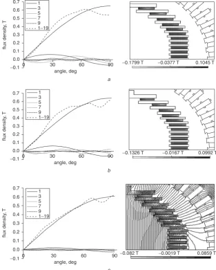
[image:2.595.315.540.23.413.2] [image:2.595.53.280.37.229.2]Fig. 4b proved very encouraging. The dimensions of the block are initially chosen arbitrarily to show the effective-ness by targeting a specific area for improvement. A wider block (by making full use of the limiting 140 mm radius from the upper most flux diverter) will almost certainly produce a better voltage waveform in that region as is shown later. Finally, in order to gain some idea on the effect of changing the local flux density on the total harmonic content of the voltage waveform, a simple formula of partial derivative was used[5]:
@ @BrðyÞ
P i41Vi2
V12
¼ 2
V12
X i41 Vi
@Vi @BrðyÞ
P i41Vi2
V2 1
V1 @V1 @BrðyÞ
ð1Þ
whereViis theith harmonic of the voltage,Bris the radial
flux density, y is the angle in degrees and other symbols have their usual meanings. This expression, although simple, provides a useful guide to target the specific area for optimisation. Figure 3 shows the total harmonic content of both phase voltage and line voltage obtained from the above expression. Hence, the flux diverters and coils were moved further away from the stator at the angle between 311to 621(see Fig. 3) and, when possible, the number of
turns in selected coils was further reduced without
compromising the earlier constraints. The results, after the final modifications, are shown in Fig. 4ctogether with the flux lines. The normal field in the coils was reduced from 0.133 to 0.086 T and the total RMS harmonic voltage content improved from 3.39 to 1.394%, thus the modifica-tions proved extremely successful.
At this stage an automated optimisation using design sensitivity analysis was undertaken. The optimisation process involved modular programming using a continuum design sensitivity formula and the commercial finite element analysis tool, OPERA[6], for calculating the sensitivity of the flux density distribution in the air-gap to determine the position of the flux diverters. The sensitivity formula was analytically derived using the material derivative concept
15 4
3 2 1 0
−1
−2
−3
−4
−5
30
angle, deg
error (
×
10
−
3)
phase voltage line voltage
45 60 75 90
Fig. 3 Weighted errors in the air-gap flux density
0.7
flux density
,
T
1 3 5 7 9
0 30 60
angle, deg
90 1−19
0.6
0.5
0.4
0.3 0.2
0.1
0.0
−0.1 −
0.1799 T
−0.1326 T −0.0167 T 0.0992 T
−0.082 T −0.0019 T 0.0859 T
−0.0377 T 0.1045 T
1 3 5 7 9 1−19
1 3 5 7 9 1−19 0.7
flux density
,
T
flux density
,
T
0 30 60
angle, deg
90 0.6
0.5 0.4
0.3
0.2
0.1
0.0
−0.1
0.7
0.6
0.5
0.4
0.3
0.2
0.1
0.0
−0.1
a
b
0 30 60
angle, deg
90
c
Fig. 4 The air-gap field and the distribution of the normal field in the HTS coils
aPreliminary modification
bVoltage waveform improvement
[image:3.595.139.453.331.722.2]and the adjoint variable technique from the variational governing equation[7, 8]. The steepest-descent method was used as a mathematical programming method to obtain the optimal point in the design parameter space.
Since the aim of this optimisation is to minimise the effects of the undesirable harmonics in the air-gap flux density, the objective functionFwas taken as:
F ¼
Z
Of
BriBrio
ð Þ2dO ð2Þ
whereBriis the radial component of the air-gap flux density,
Brio is the target value set to be 0.6 siny, y is the angle
between 01to 901andOfis the objective region whereFis
calculated. The sensitivity is defined as the total derivative of the objective function with respect to design parameters,P:
dF
dP ¼2ðBriBrioÞ dBri
dP ð3Þ
The sensitivity for the air-gap flux density was evaluated using the general sensitivity formula expressed as:
dBri
dP ¼
Z
B
GðA;lÞ^nn@X
@P dG ð4Þ
In this case,
GðA;lÞ ¼BðAÞBðlÞ ð½ nnÞ ð5Þ
whereXis the finite element node point,zis the movable interface,^nnis the outward normal vector to region 1,nis the magnetic reluctivity, Bis the curl operator, and * and ** denote region 1 and 2, respectively. In order to evaluate the numerical value of the sensitivity of (4), the state variable, A, and adjoint variable, e, were calculated using finite. element analysis. Furthermore, the adjoint variable was obtained from the adjoint system equation that has the same system matrix as the primary equation. Therefore, the adjoint equation is:
aðl;llÞ ¼
Z
Of
2ðBriBrioÞTBðllÞdO ð6Þ
where the right-hand side depicts the forcing term which results from taking the material derivative of (2).
The objective function in (2) was minimised and evaluated over a 901arc at a 160 mm radius. The objective
region was subdivided into 45 individual quadrilateral regions along the 901 arc. A total of 14 nodes, one from
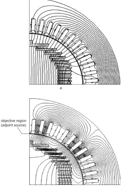
each side of the flux diverters, were selected as the design variables and allowed to move in thex-direction subject to the constraints specified previously. The flux lines and source distribution of the primary and the adjoint systems before the optimisation process are shown in Fig. 5. The flux distributions for both the systems are different due to sources being applied in different regions. A total of 25 iterations were performed to achieve the optimal position of the flux diverters as shown in Fig. 6. It can be seen that the overall voltage waveform has improved significantly which is mainly due to the upper-most ‘block’ of the flux diverter. However, the overall weight of the machine has increased somewhat in conflict with the original aim of a coreless design. Moreover, it should also be noted that a slight deterioration of normal field in the HTS coils is a side effect as only the voltage waveform was targeted in the optimisation. Nevertheless, the optimisation results are consistent with the previous modelling analysis, thus the studies have proved that a coreless design is feasible.
3.2
3D modelling
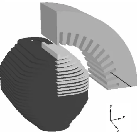
The 3D model was constructed using an available software Modeller [9]. The package allows a model to be built by creating a set of bodies and then assembling these bodies using Boolean operations. Figure 7 shows the basic features of the used model. Since the generator is simulated under a no-load condition, by exploiting symmetry and using appropriate boundary conditions, only one-eighth of the complete machine needs to be modelled. This allows a better control of the mesh with the view of minimising the error, in a total at 512 951 quadratic tetrahedral elements are used in the model.
Initially, the length of the rotor was set to 325 mm, which is the same as for the stator core. The distribution of the y-component of magnetic field along the straight line across the stator core at x¼250 mm and in thez-direction up to 162.5 mm was considered as shown in Fig. 7. The resultant distribution is shown in Fig. 8. Ideally, theycomponent of the magnetic flux density should be uniform, but unfortu-nately this cannot be achieved due to different saturation levels in the stator core. Nevertheless, an attempt was made to achieve a better uniformity of the field.
Initially, as a reasonable simplification, it was assumed that the field at z¼0 would not be affected by changes in the core length and that an increase in the area under the graph might be related to an increase in the rotor length multiplied by the field atz¼0. Hence, values of the integral of the By component divided by the flux density in the
middle were examined and compared with the actual length; objective region
(adjoint source)
a
b
Fig. 5 Flux lines for the primary and the adjoint system
aThe primary system
[image:4.595.312.545.34.395.2]a difference of 3.7 mm resulted. However, further simula-tions have shown that this assumption is not entirely correct because the variation of theycomponent of the flux density atz¼0 turned out to be more significant then expected as the axial length of the rotor was increased (with respect to the stator core). The results of the simulations are shown in Fig. 8; it can be clearly seen that a rotor length of approximately 172.5 mm yields the best field uniformity. Hence, the rotor was made longer by 10 mm and the radial
field over a patch of 901 of arc and 200 mm length at a
160 mm radius was evaluated using the modified model to extract the harmonics of the air-gap flux density. The total RMS harmonic voltage content was found to be 0.54% and the air-gap flux density was 0.51 T, which, as expected, was lower than the value obtained from 2D analysis due to saturation by leakage flux at the ends of the rotor, which is an effect unaccounted for in the 2D model.
4 Conclusions
The 2D and 3D finite element investigations reported here demonstrate the unique requirements of the superconduct-ing generator compared with a conventional design. In particular, it has been demonstrated how the magnetic field normal to the broad face of the HTS tape could be reduced below acceptable maximum levels while maintaining the necessary air-gap flux density and at the same time controlling the harmonic content of the voltage waveform. Such modelling studies have been shown to be essential before the actual design can commence.
5 References
1 Kalsi, S.S.: ‘Advances in synchronous machines employing high
temperature superconductors (HTS)’. Proc. IEEE Int. Conf. on Electric Machines and Drives, Madison, WI, USA, 2003, pp. 24–28
2 Al-Mosawi, M.K., Beduz, C., Goddard, K., Sykulski, J.K., Yang, Y.,
and Xu, B. et al.: ‘Design of a 100 kVA high temperature
super-conducting demonstration synchronous generator’, Physica C, 2002,
372–376, pp. 1539–1542
3 National Grid Report PES. TECH.218:‘High Temperature
Super-conducting Demonstrator Transformer’. University of Southampton, Southampton,UK, 1999
4 High current density wire datasheet, http://www.amsuper.com/
products/library/002-MultiFactFS01-02.pdf, American Superconduc-tor, Westborough, US, accessed 21 September 2004
5 Ship, K.S., Sykulski, J.K., and Goddard, K.F.: ‘Field optimisation in a
synchronous generator with high temperature superconducting field
winding and magnetic core’,IEE Proc., Sci., Measur. Technol., 2002,
149, (5), pp. 194–198
6 Kim, D.H., Ship, K.S., and Sykulski, J.K.: ‘ Applying continuum
design sensitivity analysis combined with standard EM software to
shape optimisation in magnetostatic problems’,IEEE Trans. Magn.,
2004,40, (2), pp. 1156–1159
7 Park, I.-H., Coulomb, J.L., and Han, S.-Y.: ‘Design sensitivity analysis
for nonlinear magnetostatic problems by continuum approach’,J. De
Phys., 1992,2, pp. 2045–2053
8 Kim, D.-H., Lee, S.-H., Park, I.-H., and Lee, J.-H.: ‘Derivation of
general sensitivity formula for shape optimization of 2D magnetostatic
systems by continuum approach’,IEEE Trans. Magn., 2002,38, pp.
1125–1128
9 OPERA’, http://www.vectorfields.co.uk/, Vector Fields Ltd, Oxford,
UK, accessed 21 September 2004
target optimised initial convergence
component Bx
0.117836 T 0.0170959 T
−0.0836443 T
flux density
,
T
objectiv
e function
0.7
0.6
0.5
0.4
0.3
0.2
0.1
0.0
0 15 30 45 60
angle, deg
90 75
1.8 1.6 1.4
1.2 1.0 0.8 0.6
0.4 0.2 0.0
Fig. 6 The comparison of voltage waveforms up to 19th odd-harmonic order and convergence rate of the optimisation process
Fig. 7 Construction of the 3D model of the HTS synchronous generator with coreless rotor
1.40
1.35
1.30
1.25
B
, T
1.20
1.15
1.10 0
0 0
250 250 250 250
local co-ordinate, mm
250 250 250
0 0 0 0 0
Z Y X
30 60 90 120 150 180
162.5 +3.7 +5 +7.5 +10 +12.5 +15 rotor length, mm
[image:5.595.51.281.31.338.2] [image:5.595.311.548.40.192.2] [image:5.595.49.283.388.614.2]