A PURELY SYMBOL-BASED PRECODED AND LDPC-CODED ITERATIVE-DETECTION
ASSISTED SPHERE-PACKING MODULATED SPACE-TIME CODING SCHEME
O. Alamri, S. X. Ng, F. Guo and L. Hanzo
∗School of ECS, University of Southampton, SO17 1BJ, UK.
Email:
[email protected]
http://www-mobile.ecs.soton.ac.uk
Abstract - In this contribution, we propose a purely symbol-based LDPC-coded scheme symbol-based on a Space-Time Block Cod-ing (STBC) signal construction method that combines orthog-onal design with sphere packing, referred to here as (STBC-SP). We demonstrate that useful performance improvements may be attained when sphere packing aided modulation is con-catenated with non-binary LDPC especially, when perform-ing purely symbol-based turbo detection by exchangperform-ing extrin-sic information between the non-binary LDPC decoder and a rate-1 non-binary inner precoder. We also investigate the con-vergence behaviour of this symbol-based concatenated scheme with the aid of novel non-binary Extrinsic Information Trans-fer (EXIT) Charts. The proposed symbol-based turbo-detected STBC-SP scheme exhibits a ’turbo-cliff’ atEb/N0 = 5.0dB
and achieves anEb/N0gain of19.2dBat aBERof10−5over Alamouti’s scheme.
1. INTRODUCTION
The benefits of transmit diversity may be exploited by employing space-time coding invoking multiple antennas both at the trans-mitter and the receiver [1, 2]. A simple yet efficient transmit di-versity scheme employing two transmit antennas was discovered by Alamouti [3]. The low complexity of Alamouti’s design fur-ther inspired Tarokhet al. [4] to generalise the transmit diversity scheme of [3] to an arbitrary number of transmit antennas using the principle of orthogonal design. Since then, the pursuit of de-signing better space-time modulation schemes has attracted con-siderable further attention [2]. The concept of combining orthogo-nal transmit diversity designs with the principle of sphere packing was introduced by Suet al. in [5], where it was demonstrated that the proposed Sphere Packing (SP) aided Space-Time Block Coded (STBC) system, referred to here as STBC-SP, was capable of outperforming the conventional orthogonal design based STBC schemes of [3, 4].
Low Density Parity Check (LDPC) codes originally devised by Gallager as early as 1963 [6] have experienced a renaissance [7] and attracted substantial research interests since the discovery of turbo codes in 1993 [8]. In 1998, Davey and MacKay proposed a non-binary version of LDPC codes [9], which was potentially capable of outperforming their binary counterpart [6].
Iterative decoding of spectrally efficient modulation schemes was considered by several authors. In [10], the employment of the turbo principle was considered for iterative soft demapping in the context of multilevel modulation schemes combined with channel decoding, where a soft demapper was used between the
∗The financial support of the European Union under the auspices of
the Newcom and Phoenix projects, as well as that of the EPSRC UK and the Ministry of Higher Education of Saudi Arabia is gratefully acknowl-edged.
multilevel demodulator and the channel decoder. In [11, 12], rate-1 inner codes were employed for designing low complexity turbo codes suitable for bandwidth and power limited systems having stringent bit-error-rate (BER) requirements.
Recently, studying the convergence behaviour of iterative de-coding has attracted considerable attention. In [13], ten Brink proposed the employment of the so-called extrinsic information transfer (EXIT) characteristics between a concatenated decoder’s output and input for describing the flow of extrinsic information through the soft in/soft out constituent decoders. EXIT charts have been extended to the non-binary (index-based) case in [14], where a histogram-based approximation of the extrinsic information was required in order to compute the mutual information. An efficient and low-complexity method of computing non-binary EXIT charts from index-baseda posterioriprobabilities was proposed in [15], which is considered a generalisation of the approach presented in [16].
Motivated by the performance improvements reported in [5], [9] and [11, 12], we propose a novel purely symbol-based itera-tive system. Given a certain effecitera-tive throughput, our simulation results demonstrate that the proposed non-binary turbo-detection aided STBC-SP scheme is capable of providing attractive perfor-mance improvements over established orthogonal STBC designs, constituted by the STBC-SP scheme of [5] as well as over a bi-nary LDPC-coded turbo-detected STBC-SP benchmarker scheme. Explicitly, as a benefit of the proposed solution, it will be demon-strated in Section 5 that the proposed turbo-detection aided STBC-SP scheme is capable of providing anEb/N0gain of19.2dBat a
Bit Error Rate (BER) of10−5over the STBC-SP scheme of [5]. The novel non-binary EXIT charts of [14] are employed for de-signing our non-binary scheme.
This paper is organised as follows. A system overview is pre-sented in Section 2. Symbol-based iterative decoding is described in Section 3. Section 4 provides our EXIT chart analysis, while our simulation results are discussed in Section 5. Finally, we conclude in Section 6.
STBC
Encoder Packing
Mapper Sphere Non−Binary
LDPC Encoder Binary
Source
T x1
T x2 D
+
[image:1.595.310.545.603.636.2]v vπ s
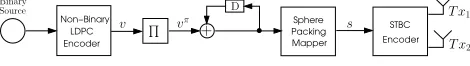
Figure 1:Symbol-Based Turbo Detection STBC-SP Encoder.
2. SYSTEM OVERVIEW
In this contribution, space-time systems employing two transmit antennas are considered, where the space-time signal is given by [3]
G2(x1, x2) =
x1 x2 −x∗2 x∗1
, (1)
Demapper Packing
Sphere
Decoder Rate−1 Non−Binary LDPC
Decoder Non−Binary
STBC
Decoder
N N
Output ? Max iteration
reached codeword Valid
?
Y Y
÷
-1
÷
Rx1
RxN
Q r
Aurc
Durc
Eurc
Aldpc
Dldpc
[image:2.595.103.498.51.159.2]Eldpc
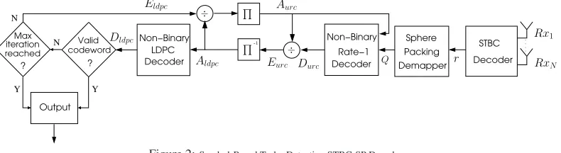
Figure 2:Symbol-Based Turbo Detection STBC-SP Decoder.
and the rows as well as columns of Equation (1) represent the tem-poral and spatial dimensions, corresponding to two consecutive time slots and two transmit antennas, respectively. The schematic of the proposed turbo-detected purely symbol-based scheme is sho-wn in Figure 1. The source bits are encoded by a rateR=12 non-binary LDPC encoder [9], to generate the LDPC encoded symbols
v = {v0, v1, . . . , vK−1}, vk ∈ GF(q), whereKis the LDPC output block length andqis the size of the LDPC decoding field. The LDPC encoded symbols are interleaved and then precoded by a non-binary rate-1 encoder, before each of them is mapped to the corresponding sphere packing modulated symbolsl ∈ S, 0≤l≤L−1. More specifically,S={sl= [a
l,1, al,2, al,3, al,4]
∈R4:0≤l≤L−1}constitutes a set ofLlegitimate
constel-lation points selected from the latticeD4having a total energy of E=lL=0−1(|al,1|2+|al,2|2+|al,3|2+|al,4|2). There is a natural one-to-one mapping betweenland the elements of the non-binary LDPC code defined overGF(q), where we haveL=q, allowing us to create a purely symbol-based system. Again, the rate-1 pre-coder shown in Figure 1 is also a non-binary enpre-coder, defined by the binary generator polynomialG= (g/gr) = (10/11), where gdenotes the feedforward output andgr is the feedback to the input using a moduloq addition. The STBC encoder then maps each sphere packing modulated symbolslto a space-time signal
Cl=
2L
EG2(xl,1, xl,2),0≤l≤L−1, such thatxl,1andxl,2 are written as
{xl,1, xl,2} = T(al,1, al,2, al,3, al,4)
= al,1+jal,2, al,3+jal,4. (2)
Subsequently, each sphere-packed space-time coded symbol is tra-nsmitted overT = 2consecutive time slots using two transmit antennas, as shown in Equation (1). More detailed discussions on orthogonal design with sphere packing modulation are provided in [17].
In this treatise, we considered a correlated narrowband Ray-leigh fading channel, associated with a worst-case-type normalised Doppler frequency offD=fdTs= 0.01, wherefdis the Doppler frequency andTsis the symbol duration. The complex fading en-velope is assumed to be constant across the transmission period of a sphere-packed space-time coded symbol, spanningT = 2time slots. The complex Additive White Gaussian Noise (AWGN) of n = nI +jnQis also added to the received signal, wherenI andnQare two independent zero mean Gaussian random vari-ables having a variance ofσn2 = σ2n
I = σ
2
nQ = N0/2per di-mension, withN0/2 representing the double-sided noise power spectral density expressed inW/Hz.
As shown in Figure 2, the received complex-valued symbols are first decoded by the STBC decoder to produce a received sphere-packed symbolr, which is fed into the sphere packing demapper, where the soft-metricQ(k)is calculated. More explicitly, the no-tationQ(k)represents the soft metric passed from the sphere pack-ing demapper to the non-binary rate-1 decoder based on the prob-ability of thekthsymbol of the encoded codeword by the rate-1
en-coder. As seen in Figure 2, the rate-1 decoder processes these soft-metrics in conjunction with thea-prioriinformation,Aurc, in or-der to generate thea-posteriori probability, Durc, where the subscripturcrefers to the unity-rate code. More specifically, the a-prioriinformation,Aurc, is provided by the LDPC decoder as the soft metric for the LDPC encoded symbols. After removing the a-prioriinformation,Aurc, from thea-posteriori probability denoted byDurc using symbol-based element-wise division, as will be shown in Section 3,Aldpcis passed asa-priori informa-tion to the LDPC decoder, which carries out a specified number of LDPC iterations and produces the decodeda-posteriori prob -ability Dldpc. Based on thea-posteriori probability, a tenta-tive hard decision will be made and the resultant codeword will be checked by the LDPC code’s parity check matrix. If the resultant vector is an all-zero sequence, then a legitimate codeword has been found, and the hard-decision based sequence will be output. Oth-erwise, if the maximum affordable number of iterations has not been reached, thea-prioriinformation,Aldpc, is removed from the a-posteriori probability denoted byDldpc using symbol-based element-wise division and fed back to the non-binary rate-1 decoder for the next iteration after appropriately reordering them using the interleaver, as seen in Figure 2. This process continues, until the affordable maximum number of iterations has been en-countered or a legitimate codeword has been found.
The structure of the binary benchmarker scheme is identical to the scheme seen in Figure 1 and Figure 2, except that the rate-1 inner code is not employed and hence iterative decoding is carried out between the outer binary LDPC code and the inner bit-based sphere packing demapper overGF(2).
3. SYMBOL-BASED ITERATIVE DECODING
For the sake of simplicity, a system having a single receive antenna is considered, although its extension to systems having more than one receive antenna is straightforward. Assuming perfect channel estimation, the complex-valued channel output symbols received during two consecutive time slots are first diversity-combined in order to extract the estimatesx˜1 andx˜2 of the most likely trans-mitted symbolsxl,1andxl,2[3][1,pp.400−401], resulting in
˜
x1 = (|h1|2+|h2|2)·xl,1+ ´w1 (3)
˜
x2 = (|h1|2+|h2|2)·xl,2+ ´w2, (4)
whereh1andh2represent the Channel Impulse Response (CIR) corresponding to the first and second transmit antennas, respec-tively, andw´1as well asw´2are zero-mean complex Gaussian ran-dom variables with varianceσ2w´1=σw2´2 = (|h1|2+|h2|2)·σ2n. A received sphere-packed symbolris then constructed from the es-timatesx˜1and˜x2using Equation (2) asr=T−1(˜x1,x˜2), where r={[˜a1,a˜2,a˜3,a˜4]∈R4}. The received sphere-packed symbol rcan be written as
r=h·
2L E ·s
l+w, (5)
whereh= (|h1|2+|h2|2),sl∈S,0≤l≤L−1, andwis a four-dimensional Gaussian random variable having a variance ofσ2w= σw2´=h·σ2n, since the symbol constellationSis four-dimensional. According to Equation (5), the conditional PDFP(r|sl)is given by
P(r|sl) = 1
(2πσw2)ND2 e−
1 2σ2w(r−α·s
l)2 ,
= 1
(2πσw)2 ND2 e−
1 2σ2w
4
i=1(˜ai−α·al,i)2
, (6)
where we haveα=h·
2L
E andND = 4, since a four-dimen-sional sphere-packed symbol constellation is used.
Similarly, the conditional PDFP(sl|r)is given by
P(sl|r) =P(r|s
l)·P(sl)
P(r) . (7)
Since the LDPC codeword consists ofK GF(q)symbols, the sphere packing demapper of Figure 2 will processK received sphere-packed symbols,(r0, r1, . . . , rK−1), at a time to produce
the following (K×L) soft-metric matrix using Equation (7)
Q= Q(0) Q(1) · · · Q(K−1) T, (8)
where,
Q(k) =P(sk=s0|rk) P(sk=s1|rk) · · · P(sk=sL−1|rk)
,
fork= 0,1, . . . , K−1. All the probabilities corresponding to a specific row inQ, which correspond to a specific received symbol, should be normalised so that they sum up to unity.
The non-binary rate-1 decoder of Figure 2 then processes the soft-metric matrixQof Equation (8) in conjunction with thea -prioriinformation,Aurc, in order to produce a decodeda-poster -iori probability matrix, Durc, of size (K×L) using a stan-dard implementation of the forward-backward recursion baseda -posteriori probability(APP) algorithm [18]. During the first iteration,P(sl), 0 ≤ l ≤ L−1, seen in Equation (7) has to be set to1/q, since noa-prioriinformation is yet available from the LDPC decoder. Thea-prioriknowledge fed into the rate-1 decoder of Figure 2 is removed from the decodeda-posteriori probabilitymatrix,Durc, using symbol-based element-wise di-vision [14] for the sake of generating theextrinsic probability matrix,Eurc, which is appropriately deinterleaved and then fed into the LDPC decoder as thea-prioriknowledge,Aldpc, as al-luded to before. More specifically, the following (K×L)a-priori information matrix is constructed
Aldpc=
Aldpc(0) Aldpc(1) · · · Aldpc(K−1) T, (9) where,
Aldpc(k) =
P(sk=s0) P(sk=s1) · · · P(sk=sL−1)
,
and we have
P(sk=sl) = (durc)lk (aurc)l k
, 0≤l≤L−1, 0≤k≤K−1,
while(durc)lkas well as(aurc)lkrefer to the elements at the cross-over point of thekth row andlthcolumn of the matricesDurc andAurc, respectively. Again, the probabilities corresponding to a specific row of the matrixAldpc should be normalised, so that the values add up to unity. The LDPC decoder exploits thea -prioriinformation,Aldpc, for the sake of producing a decoded soft-metric,Dldpc. Again, thea-prioriinformation,Aldpc, is re-moved from the decodeda-posteriori probabilitymatrix,Dldpc, by symbol-based element-wise division for the sake of generating Eldpc, which is passed to the rate-1 decoder of Figure 2 as thea -prioriknowledge,Aurc, for further iterations, until a legitimate codeword is found or the affordable maximum number of itera-tions has been exhausted.
4. NON-BINARY EXIT CHART ANALYSIS
The main objective of employing EXIT charts [13], is to predict the convergence behaviour of the iterative decoder by examin-ing the evolution of the input/output mutual information exchange between the inner and outer decoders in consecutive iterations. Denoting the mutual information between two random variables X andY asI(X;Y), the averagea-prioriinformation,IAurc, at the input of the inner non-binary rate-1 decoder and the aver-ageextrinsicinformation,IEurc, at the output of the inner non-binary rate-1 decoder can be defined as [16]
IAurc := 1 M
M−1
i=0
I(Viπ;Aurc(i)),
IEurc := 1 M
M−1
i=0
I(Viπ;Eurc(i)), (10)
whereViπis anL-ary random variable representing theithinteger symbol,vπ
i, at the input of the rate-1 encoder of Figure 1 andM is the total number of legitimate symbolsviπ. Note thatAurc(i) andEurc(i)are vectors of random variables corresponding to the ithrow of the matricesA
urcandEurc, respectively. The trans-fer characteristicTurcof the inner rate-1 decoder is a function of IAurc andEb/N0 expressed asIEurc = Turc(IAurc, Eb/N0). Similarly, the averagea-prioriinformation,IAldpc, at the input of the outer non-binary LDPC decoder and the averageextrinsic information,IEldpc, at the output of the outer non-binary LDPC decoder can be defined using Equation (10), where the subscript urcis replaced with the subscriptldpc. The transfer characteris-tic of the outer non-binary LDPC decoder is given byIEldpc =
Tldpc(IAldpc), which does not depend on theEb/N0values. The exchange of extrinsic information in the system schematic of Fig-ure 2 is visualised by plotting the extrinsic information transfer characteristics of the inner non-binary rate-1 decoder and the outer non-binary LDPC decoder in a joint diagram. This diagram is known as the Extrinsic Information Transfer (EXIT) chart [13]. As seen in Figure 2, the outer LDPC decoder’s extrinsic outputIEldpc becomes the inner rate-1 decoder’sa-prioriinputIAurc, which is usually represented on thex-axis of the EXIT chart. Similarly, on they-axis of the EXIT chart, the inner rate-1 decoder’s extrinsic outputIEurc becomes the outer LDPC decoder’sa-prioriinput
IAldpc, as seen in Figure 2. The mutual informationI(Vπ
i ;Aurc(i))in Equation (10) can be expressed as [14, 16]
I(Viπ;Aurc(i)) = L−1
vπ i=0
aurc(i)
p(aurc(i)|viπ) P(viπ)
· log2
p(aurc(i)|vπ i) p(aurc(i))
daurc(i), (11)
with
p(aurc(i)) = L−1
vπ i=0
p(aurc(i)|viπ) P(viπ), (12)
and thea-priori probabilities P(vπ
i) for the indices vπi. The L-dimensional integration in (11) can be evaluated numerically, where the pdfp(aurc(i)|vπi)may be obtained analytically by gen-eratingAurc(i)by observing theL-ary received symbolVπ
i arriv-ing over alog2(L)-dimensional Gaussian channel, assuming that thelog2(L)bits corresponding toViπare independent [14]. The term,I(Vπ
i ;Eurc(i))can also be expressed using Equations (11) and (12), whereaurc(i)is replaced witheurc(i). This requires the determination of the distribution ofp(eurc(i)|vπ
i)by means
of Monte Carlo simulations and computing anL-dimensional his-togram [13, 14]. However, a more efficient computation of non-binary EXIT functions was proposed in [15] that requires neither the computation of theL-dimensional histogram nor the evalu-ation of theL-dimensional integration in Equation (11). It was shown in [15] that by averaging over a sufficiently large number of length-Kblocks, the mutual informationIEcan be estimated as
IE=−H(V1) +E
1 K
K−1
i=0 L−1
l=0
elk
, (13)
whereelkrefers to the element at the cross-over point of thekth row andlthcolumn of the matricesE
urcorEldpcand the entropy H(V1)can be readily determined from thea-priori L-ary symbol distributionsP(vi). For example, if we haveP(vi =l) = 1/L, forl = 0,1, . . . , L−1, (i.e. equiprobableL-ary symbols), then arrive atH(V1) =−log2(L).
0.0 0.5 1.0 1.5 2.0 2.5 3.0 3.5 4.0
IEof LDPC decoder becomes IAof rate-1 decoder
0.0 0.5 1.0 1.5 2.0 2.5 3.0 3.5 4.0
IE
of
rate-1
decoder
becomes
IA
of
LDPC
decoder Symbol-Based STBC-SP, L=16 Non-Binary Exit Chart
3 LDPC iterations Non-Binary LDPC Code
Eb/N0= 5.0dB
Eb/N0= 4.5dB
[image:4.595.358.483.53.176.2]Non-Binary Rate-1 Code
[image:4.595.99.222.250.372.2]Figure 3:EXIT chart of a non-binary LDPC-coded STBC-SP scheme in combi-nation with the12-rate outer non-binary LDPC code [9] defined overGF(16)using three internal LDPC iterations and the system parameters outlined in Table 1.
Figure 3 shows the EXIT chart of the turbo-detection aided, non-binary LDPC-coded STBC-SP scheme of Figure 2 in con-junction with the system parameters outlined in Table 1. Ideally, in order for the exchange of extrinsic information between the rate-1 decoder and the outer LDPC decoder of Figure 2 to converge at a specificEb/N0 value, the extrinsic transfer curve of the rate-1 decoder recorded at theEb/N0 value of interest and the
extrin-sic transfer characteristic curve of the outer LDPC decoder should only intersect at the point(IA, IE) = (4.0,4.0). If this condition is satisfied, then a so-calledconvergence tunnel[13] appears in the EXIT chart. The narrower the tunnel, the closer the sys-tem’s performance to the channel capacity and hence in the spirit of Shannonian information theory more iterations are required for reaching the(4.0,4.0)point. This is particularly so beyond the cut-off rate of the channel, which is often referred to as the ’prac-tical’ channel capacity. Observe in Figure 3 that an open conver-gence tunnel is taking shape upon increasing the signal-to-noise ratio fromEb/N0= 4.5dBtoEb/N0= 5.0dB. This implies that according to the predictions of the EXIT chart seen in Figure 3, the iterative decoding process is expected to converge and hence an in-finitesimally lowBERmay be attained beyondEb/N0= 5.0dB. However, a highBERis expected forEb/N0<4.5dBdue to the
intersection of the extrinsic transfer characteristic curves at a low IE value, as seen in Figure 3. These EXIT chart based conver-gence predictions are usually verified by the actual iterative de-coding curves and trajectory, as it will be discussed in Section 5.
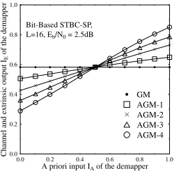
Figure 4 shows the extrinsic information transfer characteris-tics of the bit-based LDPC benchmarker sphere-packing demap-per of in conjunction withL= 16, when using different mapping schemes between the binary LDPC encoder’s output and the STBC
0.0 0.2 0.4 0.6 0.8 1.0
A priori input IAof the demapper
0.0 0.2 0.4 0.6 0.8 1.0
Channel
and
extrinsic
output
IE
of
the
demapper
. . . .
L=16, Eb/N0= 2.5dB
Bit-Based STBC-SP,
AGM-4 AGM-3 AGM-2 AGM-1
.
GMFigure 4:Sphere packing demapper extrinsic information transfer characteristics for Gray mapping (GM) and different bits to sphere-packing symbol anti-Gray map-ping (AGM) schemes atEb/N0 = 2.5dBforL = 16, when communicating over a correlated Rayleigh fading channel having a normalised Doppler frequency of
fD= 0.1.
encoder. Accordingly, binary EXIT chart analysis [13] was em-ployed for studying the convergence of the bit-based benchmarker scheme. As was reported in [10], Gray mapping does not always provide an iteration gain upon increasing the mutual information at the input of the demapper. However, using a variety of differ-ent Anti-Gray mapping (AGM) schemes [10] results in differdiffer-ent extrinsic information transfer characteristics, as illustrated by the different slopes seen in Figure 4. The four different AGM mapping schemes1−4shown in Figure 4 were specifically selected by ex-haustive search from all the16!possible mapping schemes avail-able forL = 16in order to demonstrate the different extrinsic information transfer characteristics associated with different bit-to-symbol mapping schemes.
0.0 0.2 0.4 0.6 0.8 1.0
IEof LDPC decoder becomes IAof demapper
0.0 0.2 0.4 0.6 0.8 1.0
IE
of
demapper
becomes
IA
of
LDPC
decoder
Binary Exit Chart
3 LDPC iterations Binary LDPC Code
Eb/N0= 5.5dB
Eb/N0= 5.0dB
Eb/N0= 4.5dB
L=16, AGM-2 Bit-Based STBC-SP,
Figure 5:EXIT chart of a turbo-detected binary LDPC-coded STBC-SP scheme employing the Anti-Gray mapping (AGM-2) of Figure 4 in combination with the12 -rate outer binary LDPC code [6] using three internal LDPC iterations and the system parameters outlined in Table 1.
The EXIT chart of the turbo-detected binary LDPC-coded STBC-SP scheme employing the Anti-Gray mapping 2 of Figure 4 in combination with the system parameters outlined in Table 1 is por-trayed in Figure 5. According to the figure, a convergence tunnel appears atEb/N0= 5.0dB, but the extrinsic transfer characteris-tic curves of the bit-based sphere-packing demapper and the outer binary LDPC decoder intersect at a point infinitesimally close to theIE = 1.0line, which indicates that a relatively lowBER may be attained for this particular system arrangement. Nonethe-less, there would be aBER floor preventing the system from achieving an infinitesimally lowBER, which is in contrast to the non-binary scheme of Figure 2, where the non-binary EXIT chart seen in Figure 3 demonstrated that convergence to the point (IA, IE) = (4.0,4.0)was possible. However, the intersection of
[image:4.595.357.481.404.527.2]the extrinsic transfer characteristic curves of the bit-based sphere-packing demapper and the outer binary LDPC decoder plotted in Figure 5 tends to slide upwards, approaching theIE = 1.0 line upon gradually increasing theEb/N0 values. Hence, it is
expected that a reasonably lowBERmay be attained even for Eb/N0 < 5.0dB, although theBERreduction versusEb/N0
increase would be only gradual, indicating the existence of a non-dominantBERfloor, as it will be highlighted in the context of the BERcurve of Figure 9.
5. RESULTS AND DISCUSSION
Without loss of generality, we considered a sphere packing mod-ulation scheme associated withL = 16using two transmit and a single receiver antenna in order to demonstrate the performance improvements achieved by the proposed system. The specific sub-set ofL= 16points selected from the entire set of legitimate con-stellation points hosted byD4was chosen based on the minimum-energy and optimum minimum Euclidean distance criterion pro-posed in [17]. All simulation parameters are listed in Table 1.
Modulation Sphere Packing withL= 16
No. of Transmitters 2
No. of Receivers 1
Channel Correlated Rayleigh Fading
Normalised Doppler
frequency 0.1
Average LDPC
column weight 2.5
LDPC coding rate 0.5
Non-Binary LDPC
decoding field GF(16)
System throughput 1bit/symbol
[image:5.595.342.497.50.170.2]LDPC Coded Blocklength 6000bits
Table 1:System parameters
0 1 2 3 4
IEof LDPC decoder becomes IAof rate-1 decoder
0 1 2 3 4
IE
of
rate-1
decoder
becomes
IA
of
LDPC
decoder
(Eb/N0= 5.0dB) Rate-1 Code Non-Binary
[image:5.595.77.259.267.375.2]trajectory Decoding (3 LDPC iters) LDPC Code Non-Binary
[image:5.595.355.483.284.409.2]Figure 6:Decoding trajectory of the symbol-based12-rate LDPC [9] coded STBC-SP scheme in combination with the system parameters outlined in Table 1 and operat-ing atEb/N0= 5.0dBafter five joint external iterations and three internal LDPC iterations.
Figure 6 illustrates the actual decoding trajectory of the turbo-detected non-binary LDPC-coded STBC-SP scheme of Figure 3 at Eb/N0 = 5.0dBafter five joint external iterations. The
zigzag-path seen in Figure 6 represents the actual extrinsic information transfer between the rate-1 inner decoder and the outer non-binary LDPC decoder atEb/N0 = 5.0dB. The deviation of the
decod-ing trajectory from the prediction of the EXIT chart in Figure 3 is due to the fact that the assumption of havinglog2(L) indepen-dent bits corresponding to each indexVi is only approximately valid. This assumption was exploited when creatingAurc(i)for the sake of generating the appropriatea-priori informationIA value to characterise the extrinsic information transfer characteris-tics of the constituent decoders. However, theBERcurves of the
0 1 2 3 4 5 6 7 8 9 10 Eb/N0[dB]
10-7 10-6 10-5 10-4 10-3 10-2 10-1 100
BER
(3 LDPC iters) Non-binary LDPC STBC-SP, L=16 Symbol-based
no precoding 5 iters
4 iters 3 iters 2 iters 1 iter
no iter precoder with rate-1
Figure 7: Performance of symbol-based 12-rate LDPC [9] coded STBC-SP schemes in combination with the system parameters outlined in Table 1 after five joint external iterations and three internal LDPC iterations.
scheme characterised in Figure 3, which are shown in Figure 7, match the predictions of the EXIT chart quite accurately in Fig-ure 3, since the predicted turbo cliff atEb/N0 = 5.0dBand the
associated infinitesimally lowBERbecome quite evident.
0.0 0.2 0.4 0.6 0.8 1.0
IEof LDPC decoder becomes IAof demapper
0.0 0.2 0.4 0.6 0.8 1.0
IE
of
demapper
becomes
IA
of
LDPC
decoder
(Eb/N0= 5.0dB)
L=16, AGM-2 Bit-Based STBC-SP,
trajectory Decoding (3 LDPC iters) Binary LDPC Code
Figure 8: Decoding trajectory of a bit-based LDPC-coded STBC-SP scheme in conjunction with Anti-Gray Mapping (AGM-2) and in combination with the system parameters outlined in Table 1 after10joint external iterations and three internal LDPC iterations.
0 2 4 6 8 10 12 14
Eb/N0[dB] 10-7
10-6 10-5 10-4 10-3 10-2 10-1 100
BER
(3 LDPC iters) Binary LDPC, L=16, AGM-2 STBC-SP, Bit-based
10 joint iters 3 joint iters 2 joint iters 1 joint iter no joint iter
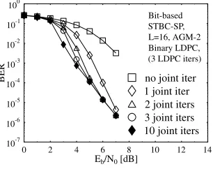
Figure 9:Performance of a bit-based LDPC-coded STBC-SP scheme in conjunc-tion with Anti-Gray Mapping (AGM-2) and in combinaconjunc-tion with the system param-eters outlined in Table 1 after10joint external iterations and three internal LDPC iterations.
Figure 8 illustrates the decoding trajectory of the 12-rate turbo-detected binary LDPC [6] coded STBC-SP scheme of Figure 5 operating atEb/N0 = 5.0dB after10joint external iterations
and three internal LDPC iterations. Observe in Figure 8 that three joint external iterations was sufficient for reaching the intersec-tion point. Figure 9 shows theBERperformance of the bit-based LDPC-coded STBC-SP scheme of Figure 5. The gentle slope of theBERcurve seen in Figure 9 matches the predictions of the
[image:5.595.100.222.417.544.2] [image:5.595.344.497.480.601.2]EXIT chart seen in Figure 5. Additionally, note that theBER curves after three and10joint external iterations become almost identical forEb/N0 > 4.0dB, since having three joint external iterations is sufficiently high for achieving the highest possible it-eration gain, as observed for the decoding trajectory of Figure 9.
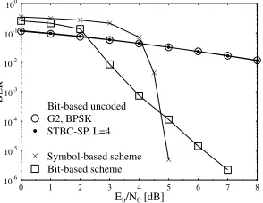
[image:6.595.89.236.363.477.2]Figure 10 compares the attainable performance of both the sym-bol-based non-binary LDPC-coded STBC-SP scheme and the bit-based LDPC-coded STBC-SP scheme in conjunction with Anti-Gray Mapping (AGM-2) when using the system parameters out-lined in Table 1 after five joint external iterations and three inter-nal LDPC iterations against an identical-throughput 1 bit/symbol (BPS) uncoded STBC-SP scheme [5] usingL = 4and against Alamouti’s conventionalG2-BPSK scheme [3]. Observe the dif-ference in Figure 10 between the slope of the symbol-based and bit-based schemes, which was as expected for the EXIT chart re-sults. Additionally, a useful performance improvement was ob-tained, when performing iterative decoding between the rate-1 in-ner and the non-binary outer LDPC decoders. Explicitly, Fig-ure 10 demonstrates that a coding advantage of about 19.2dB was achieved at a BER of10−5after five joint external iterations by the symbol-based non-binary LDPC-coded STBC-SP scheme when, using three internal LDPC iterations over both the uncoded STBC-SP [5] and the conventional orthogonal STBC design based schemes [3, 4] for transmission over the correlated Rayleigh fad-ing channel havfad-ingfD= 0.1. Additionally, a coding advantage of approximately1.3dBwas attained over the 1BPS-throughput bit-based LDPC-coded STBC-SP scheme in conjunction with Anti-Gray Mapping (AGM-2), when using the system parameters of Table 1.
0 1 2 3 4 5 6 7 8 Eb/N0[dB]
10-6 10-5
10-4
10-3
10-2 10-1
100
BER
. . . .
. .
.
STBC-SP, L=4G2, BPSK Bit-based uncoded
Bit-based scheme Symbol-based scheme
Figure 10: Performance comparison of the symbol-based 12-rate non-binary LDPC [9] coded STBC-SP scheme and the bit-based12-rate binary LDPC [6] coded STBC-SP scheme in conjunction with the Anti-Gray Mapping (AGM-2) and in com-bination with the system parameters outlined in Table 1 after five joint external itera-tions and three internal LDPC iteraitera-tions against an identical-throughput 1 bit/symbol (BPS) uncoded STBC-SP scheme usingL= 4and against Alamouti’s conventional
G2-BPSK scheme.
6. CONCLUSION
In this paper we proposed a novel symbol-based iterative system that exploits the advantages of non-binary LDPC codes [9], those of the rate-1 inner codes of [11] as well as those of the STBC-SP scheme of [5]. Our investigations demonstrated that signifi-cant performance improvements may be achieved by the proposed scheme over established orthogonal STBC designs, constituted by the STBC-SP scheme of [5] as well as over an equivalent bit-based LDPC-coded STBC-SP scheme. Subsequently, non-binary EXIT charts were used to study the convergence of the proposed symbol-based scheme. By contrast, binary EXIT charts were used for designing the bit-based binary LDPC-coded STBC-SP scheme’s optimum bit-to-symbol mapping schemes, which facilitated con-vergence at the lowest possibleEb/N0 values. Several
STBC-SP mapping schemes covering a wide range of extrinsic trans-fer characteristics were investigated. Our analysis demonstrated
that useful performance improvements can be obtained, when per-forming iterative decoding between the rate-1 inner and the outer non-binary LDPC decoders over the uncoded STBC-SP arrange-ment [5], as well as over the conventional orthogonal STBC de-sign based schemes [3, 4] and the bit-based LDPC-coded STBC-SP scheme
7. REFERENCES
[1] L. Hanzo, T. H. Liew, and B. L. Yeap,Turbo Coding, Turbo
Equali-sation and Space-Time Coding: for Transmission over Fading Chan-nels. Chichester, England: John Wiley and Sons Ltd and IEEE Press, NY, USA, 2002.
[2] B. M. Hochwald, G. Gaire, B. Hassibi, and E. T. L. Marzetta, “Spe-cial issue on space-time transmission, reception, coding and
sig-nal processing,”IEEE Transactions on Information Theory, vol. 49,
pp. 2329–2806, Oct 2003.
[3] S. Alamouti, “A simple transmit diversity technique for wireless
communications,”IEEE Journal on Selected Areas in
Communica-tions, vol. 16, no. 8, pp. 1451–1458, 1998.
[4] V. Tarokh, H. Jafarkhani, and A. Calderbank, “Space-time block
codes from orthogonal designs,”IEEE Transactions on Information
Theory, vol. 45, pp. 1456–1467, Jul 1999.
[5] W. Su, Z. Safar, and K. J. R. Liu, “Space-time signal design for
time-correlated Rayleigh fading channels,” inIEEE International
Confer-ence on Communications, vol. 5, (Anchorage, Alaska), pp. 3175– 3179, 2003.
[6] R. Gallager, “Low density parity check codes,”IEEE Transactions
on Information Theory, vol. 8, pp. 21–28, Jan. 1962.
[7] T. Richardson and R. Urbanke, “The renaissance of Gallager’s
low-density parity-check codes,”IEEE Communications Magazine,
vol. 41, pp. 126–131, Aug 2003.
[8] C. Berrou, A. Glavieux, and P. Thitimajshima, “Near Shannon limit
error-correcting coding and decoding: Turbo codes,”Proceedings of
the IEEE International Confrence on Communications, pp. 1064– 1070, May 1993.
[9] M. C. Davey and D. J. C. MacKay, “Low density parity check codes
over GF(q),” IEEE Communications Letters, vol. 2, pp. 165–167,
June 1998.
[10] S. ten Brink, J. Speidel, and R.-H. Yan, “Iterative demappping and
decoding for multilevel modulation,” inIEEE Global
Telecommuni-cations Conference, vol. 1, (Sydney, Australia), pp. 579–584, 8-12 Nov 1998.
[11] D. Divsalar, S. Dolinar, and F. Pollara, “Serial concatenated trellis
coded modulation with rate-1 inner code,” inIEEE Global
Telecom-munications Conference, vol. 2, pp. 777–782, 27 Nov-1 Dec 2000. [12] L. Lifang, D. Divsalar, and S. Dolinar, “Iterative demodulation,
demapping, and decoding of coded non-square QAM,” in IEEE
Transactions on Communications, vol. 53, pp. 16–19, Jan 2005. [13] S. ten Brink, “Designing iterative decoding schemes with the
extrin-sic information transfer chart,”AEU¨ International Journal of
Elec-tronics and Communications, vol. 54, pp. 389–398, Nov 2000.
[14] A. Grant, “Convergence of non-binary iterative decoding,” IEEE
Global Telecommunications Conference, vol. 2, pp. 1058–1062, Nov 2001.
[15] J. Kliewer, S. X. Ng, and L. Hanzo, “On the computation of exit
characteristics for symbol-based iterative decoding,”to appear in 4th
International Symposium on Turbo Codes in connection with 6th In-ternational ITG-Conference on Source and Channel Coding, 2006. [16] I. Land, P. Hoeher, and S. Gligorevic, “Computation of symbol-wise
mutual information in transmission systems with logAPP decoders
and application to EXIT charts,” inProceedings of the International
ITG Conference on Source and Channel Coding (SCC), (Erlangen, Germany), pp. 195–202, Jan 2004.
[17] O. Alamri, B. L. Yeap, and L. Hanzo, “Turbo detection of
channel-coded space-time signals using sphere packing modulation,” inIEEE
Vehicular Technology Conference, vol. 4, (Los Angeles, USA), pp. 2498–2502, Sep 2004.
[18] L. Bahl, J. Cocke, F. Jelinek, and J. Raviv, “Optimal decoding of
linear codes for minimizing symbol error rate,” inIEEE Transactions
on Information Theory, vol. 20, pp. 284–287, March 1974.