City, University of London Institutional Repository
Citation
:
Gorasia, R. J., McNamara, A. M. & Rettura, D. (2012). Reducing driving forces
for pressed-in piles. Proceedings of the Institution of Civil Engineers - Geotechnical
Engineering, 167(1), pp. 19-27. doi: 10.1680/geng.11.00084
This is the published version of the paper.
This version of the publication may differ from the final published
version.
Permanent repository link: http://openaccess.city.ac.uk/8127/
Link to published version
:
http://dx.doi.org/10.1680/geng.11.00084
Copyright and reuse:
City Research Online aims to make research
outputs of City, University of London available to a wider audience.
Copyright and Moral Rights remain with the author(s) and/or copyright
holders. URLs from City Research Online may be freely distributed and
linked to.
Reducing driving forces for
pressed-in piles
j1 Rohit Jay GorasiaMEng
PhD researcher, Geotechnical Engineering Research Centre, City University, London, UK
j2 Andrew Martin McNamaraMSc, PhD
Senior lecturer, Geotechnical Engineering Research Centre, City University, London, UK
j3 Domenico RetturaMSc
Student, Universita` degli Studi di Roma ‘La Sapienza’, Facolta’ di Ingegneria, Rome, Italy
j1 j2 j3
Pile jacking techniques use static loading to install sheet piles with minimal environmental effects, such as noise and ground vibrations, which are often associated with other methods of driven piling. This paper describes a series of 20g centrifuge tests conducted to investigate two methods of reducing the large driving forces that can be associated with jacked sheet piles in stiff clay. In practice, pre-auguring at the clutch positions and water jetting techniques are routinely carried out prior to the installation of sheet piling in order to reduce the driving forces. However, these methods are known to contribute to ground movements and can detract from the advantages of jacked sheet piles. The tests involved driving model sheet piles, which were modified either by installing driving shoes to the base of the pile, or by ribbing the profile of the pile shaft. The driving forces of the modified piles were compared with those of a plain pile. The tests showed that the use of driving shoes and ribs can lead to the reduction of driving forces at greater depth.
Notation
d diameter of the T-bar cylinder (m)
g gravity
M slope of CSL projected toq9:p9plane
N specific volume of normally consolidated soil at
p9¼1.0 kPa
Nb bar factor
P force per unit length acting on the cylinder
p9 mean normal effective stress
Su undrained shear strength v specific volume of the soil
ˆ specific volume of soil on the critical state line at
p9¼1.0 kPa
º gradient of compression line inv:lnp9space
9 critical state angle of friction.
9h horizontal effective stress
9v horizontal effective stress
1. Introduction
The introduction of silent piling methods has enabled the use of sheet piled walls in urban developments, where bored piles are usually the method of choice. While pressed-in sheet piled walls can be installed quickly and accurately, the installation of sheet piled walls in stiff overconsolidated soils such as
London Clay often requires initial pre-auguring at the pile clutch positions and then water jetting during the press-in process to reduce the jacking force needed. Both of these activities are potential contributors to ground movement and any measures that can be taken to avoid them could be beneficial when installing sheet piles near sensitive structures or buried services.
2. Background
Finlayet al.(2001) conducted three pile installation tests in Japan using the press-in method. They used an instrumented double-skin tubular pile allowing the independent measurement of internal and external shaft friction and base resistance. The pile was installed with and without internal and external driving shoes, and the consequent reduction in shaft friction was examined. Their results showed internal and external shaft friction reductions by factors of 3 and 4 respectively. These changes are consistent with a reduction in the earth pressure coefficient (9h=9v) adjacent to the pile shaft to the active condition as the soil flows past the driving shoe.
the additional area of the driving shoes. However, it was suggested that the increase in base resistance could be reduced if a smaller driving shoe was used.
The observed decrease in shaft resistance related to steel tubular piles. However, this theory should hold for steel sheet piles as, apart from the geometry, there are very few differences. The present paper explains similar techniques applied to sheet piles to explore the influence of the profile of the pile tip and pile roughness on driving force in small-scale models using the geotechnical centrifuge at City University, London, UK.
The tests reported use a ‘double-edged’ shoe as opposed to the internal and external shoes used by Finlay et al. (2001). Sampling of various shoe sizes is necessary to optimise the phenomenon of the base resistance increasing to partially balance the decrease of the shaft friction. The experiment involved centrifugal modelling of jacked sheet pile installation at 20g using both plain and modified sheet piles based on the geometry shown in Figure 1.
The experiments involved individually driving each sheet pile into the soil sample at a constant rate and measuring the driving force needed as the pile became embedded. In total, 11 tests were conducted and the results of similar repeated tests were compared with the results of the experiments using the plain control pile.
3. Apparatus and testing
Five model piles were manufactured in total. Most of the piles were formed from 3.125 mm (1/8 in) thick mild steel plate, which was milled to a thickness of 1 mm, leaving 1 mm outstanding ribs at the required spacing or a 1 mm wide toe, as required. One pile was milled from 5 mm thick plate where a particularly wide toe was required. The control (smooth) pile was also provided with a milled finish to ensure consistency in
surface roughness between all piles. When the piles had been milled to the correct thickness they were formed into the required profile in a sheet folder.
The model was contained in a standard 420 mm diameter by 405 mm tall stainless steel centrifuge tub. A 10 mm thick plate was fixed above the container using 65 mm packers threaded through M8 studs to gain additional height. Attached to the plate was a gear box and lead screw (Figure 2).
A significant problem exists with modelling sheet piles in the centrifuge owing to scale. Sheet piles are by their nature very slender elements and, even at a scale of one-twentieth of their full size, which is quite a large scale in terms of centrifuge modelling, they become very small. A smaller scale factor would mean that the modelling of intricate elements, such as pile ribs, would become difficult. Problems also arise when pushing a long, slender section into a soil sample without lateral restraint. It was therefore only possible to model a short 3 m embedded length at prototype scale, although this proved to be sufficient to demonstrate the benefits of modified sheets. Tradi-tional top-driven sheet piles are often subject to issues concern-ing the slenderness ratio; however, this is less apparent with press-in piling, where the piles are driven from the top of the soil. The slenderness ratios of the piles used for the tests were significantly lower than for typical prototype, top-driven piles. The use of short piles also enabled the experiments to be conducted in a standard centrifuge container, with boundaries sufficiently far from the area of interest, so as to have negligible influence. Craig (1995) suggests the minimum distance from any
170 mm
120°
12 mm
[image:3.595.304.531.525.771.2]25 mm
Figure 1.Typical overall dimensions of model piles
Lead screw
Motor and gear box
65 mm packers
Test pile
Force plate
Consolidated kaolin clay
170 mm
Figure 2.Arrangement of testing apparatus Geotechnical Engineering
Volume 167 Issue GE1
Reducing driving forces for pressed-in piles
[image:3.595.45.276.594.767.2]boundary for a pile should be five diameters; in this case the distance was a minimum of 6.5 diameters.
Driving shoes were provided at the base of two sheet piles such that they protruded equally on both sides of the pile. The width of the shoe flange was 5 mm on one of the sheet piles and 3 mm on the other, compared to the control pile which had no driving shoe and a plate thickness of 1 mm (Figure 3).
The profiles of the shafts of two sheet piles were provided with ribs. The spacing between the ribs was 10 mm on one of the sheet piles and 20 mm on the other. The ribs were 1 mm thick (Figure 4). The dimensions of both piles can be seen in Figure 5. The purpose of the testing series was to compare pile ribs to pile shoes, and the dimensions of these features were chosen accordingly.
3.1 Instrumentation
The driving force required to embed the sheets was measured using a force plate consisting of three standard load cells sandwiched between two stiff (10 mm thick) aluminium plates (Figure 6). The force plate enabled any bending that may exist at the head of the model sheet pile to be eliminated and the total driving force was simply the sum of the forces measured in the three load cells.
An instrumented T-bar penetrometer based on Stewart and Randolph (1991) was used to profile the undrained shear strength of the soil in flight, but after pile driving. The penetrometer consisted of a 7 mm diameter rod connected to a hollow tube, by way of a short length of thin-walled hypoder-mic tube, to which the strain gauges were attached. The T-bar used four strain gauges in a full bridge circuit to compensate for bending and only measured axial strain, while simulta-neously compensating for temperature changes, lead wire resistance and Poisson ratio effects. A brush-on neoprene coating applied to the strain gauges provided protection from dirt and moisture (Figure 7).
From the force on the T-bar, the shear strength was estimated using the following simple expression
P=ðSudÞ ¼ Nb
wherePis the force per unit length acting on the cylinder (kN),
dis the diameter of the cylinder (m), Su is the undrained shear strength of the soil (kPa) andNb is the bar factor. Randolph and Houlsby (1984) recommend that an intermediate value for Nbof 10.5 could be adopted for general use.
3.2 Preparation of soil sample and model making
[image:4.595.322.550.140.275.2]The soil used for testing was speswhite kaolin clay consolidated under a pressure of 850 kPa from slurry with a water content of Plain pile 3 mm wide toe 5 mm wide toe
Figure 3.Plain control pile compared with similar piles with 3 mm and 5 mm driving shoes
Plain pile
1 mm ribs at 10 mm centres
1 mm ribs at 20 mm centres
Figure 4.Plain control pile compared with similar piles with 1 mm outstanding ribs at 10 mm centres and 20 mm centres
1
3
5
11
1
1
20 Plain pile
3 mm shoe
5 mm shoe
Ribs at 10 mm centres
[image:4.595.58.295.345.458.2]Ribs at 20 mm centres
[image:4.595.58.296.522.753.2]120% to produce a stiff sample with average undrained shear strength of about 120 kPa. Table 1 details the speswhite kaolin soil parameters.
[image:5.595.42.278.135.509.2]The soil in this sample could reasonably be assumed to be able to stand unsupported between the pile ribs for some time during testing. The tests were carried out as soon as possible after the soil sample was removed from the consolidation press and, in order to allow this, the apparatus was designed in such a way as to permit simple installation on to the top of the tub. In practice it took less than 30 min to remove the sample from the consolida-tion press and install it on the centrifuge swing ready for spin up for the first test. Owing to the space needed to employ the force plate it was necessary to spin up and test each pile individually, followed by a final spin up to profile the soil using the T-bar. The soil sample was therefore used for four separate tests: three for the sheet piles and one for the penetrometer. The penetrometer results confirmed an average value ofSu¼120 kPa, as shown in
Figure 8, although some hand vane tests were also carried out immediately after pile installation as a check.
It is normal practice to seal the surface of a clay model with silicone oil or similar to prevent drying during flight. However, a preliminary trial showed that oil could easily be drawn into the void created around the pile toe or ribs. In view of this it was decided that the top of the clay should be sealed with much more viscous silicone grease, over the entire surface area, but this was omitted in the immediate vicinity of the piles. Leaving the small area of the test site unsealed was justified because the tests were carried out quickly and with minimal drying during the short spin up time.
3.3 Centrifuge model testing
Testing consisted of accelerating the model on the centrifuge swing to 20g and then immediately driving a pile into the clay sample at a constant rate of 85 mm/min; this was the maximum speed at which the actuator was able to work and is quite slow in comparison to the prototype, although this could still be regarded as generally undrained. There was no period of consolidation prior to pile driving and the soil therefore had a stiffness profile that was very similar to that at 1g. The output logged from each test was load and displacement.
4. Test results
The results of two series of tests, each on three piles, are reported. In each series, test type A explored the effect of providing a driving shoe at the toe of the piles, whereas test type B explored the effect of ribs (Table 2). The two series of tests were identical but carried out by different researchers and the consistency between the two sets of results is itself worthy of note. Often testing by different researchers can yield slightly different results, owing to dissimilar model-making procedures.
Data have been presented as the driving force required to embed the piles with shoes (type A) or ribs (type B), normalised by the driving force required for the equivalent plain pile. It should be noted that for every test in which modified piles were installed, a plain pile was also installed as a reference, thereby ensuring that the effects of any inconsistency between soil samples used for individual experiments could be assumed to have been elimi-nated. The initial scatter in the data can be attributed to the pile tip overcoming the bearing capacity at the soil surface.
4.1 Test type A
Figure 9 shows the load–displacement graph for the piles with large driving shoes normalised by the driving force for a plain pile without a driving shoe. Initially, and as expected, both piles with driving shoes required a greater force to overcome the base resistance. This is verified by comparing the increase in base area with the increase in normalised driving force, which are both of similar magnitude. However, the relative driving force then reduced with increasing penetration for the 5 mm wide driving shoe. At the deepest penetration the force required to drive this
Figure 6.Force plate used to ensure that eccentric loads in model sheet piles did not distort measurement of driving force
Geotechnical Engineering
Volume 167 Issue GE1
Reducing driving forces for pressed-in piles
Indicates centre-line of strain gauge 1 1 mm groove
to receive wires⫻
6, 35
Tube glued into vertical bar
7·72 10
20
5° taper
7
5
35
[image:6.595.83.531.134.552.2](b) (a)
Figure 7.T-bar penetrometer (Gorasia, 2010): (a) details of T-bar penetrometer; (b) T-bar penetrometer in loading frame with motor (dimensions in mm)
LL Liquid limit 65
PL Plastic limit 35
º Gradient of compression line inv:lnp9space 0.18
ˆ Specific volume of soil on the critical state line (CSL) atp9¼1.0 kPa 2.994
N Specific volume of normally consolidated soil atp9¼1.0 kPa 3.05
M Slope of CSL projected toq9:p9plane 0.89
9 Critical state angle of friction 238
pile was, surprisingly, about 30–40% less than that required for the plain pile, suggesting a decrease in friction between the faces of the pile and the soil. The significant reduction in driving force appears to be sustained at depth.
In Figure 10 the driving shoe appears equally effective at a
reduced width of 3 mm. Initially, and as expected, the increased driving force required to overcome the bearing capacity under the toe was somewhat less than the 5 mm wide shoe. Thereafter, the driving force required with the shoe was soon less than that for the plain pile and a similar maximum reduction of 30–40% was consistently seen in three separate experiments which sought to explore the consistency of the results. Towards the end of the test, the normalised driving force shown in Figure 10 may be at a constant level, but it would be equally valid to suggest that the efficacy of the driving shoe was reducing and that if the data were to be extrapolated then the normalised data would increase towards and perhaps beyond unity. Tests using deeper model piles would be needed to explore this.
[image:7.595.44.278.139.291.2]4.2 Test type B
Figure 11 shows the load–displacement graph for two piles with ribs at 20 mm spacing over their entire length. The driving force for the ribbed piles has again been normalised by the driving force
0 1 2 3 4
0 20 40 60 80 100 120 140
Normalised driving for
ce
Displacement: mm Test series 2, dotted line
Test series 1, solid line
Plain pile
30–40% reduction
Figure 9.Load–displacement graphs for piles with large (5 mm wide) driving shoes normalised by the force required to drive the plain pile 0 1 2 3 4
0 20 40 60 80 100 120 140
Normalised driving for
ce
Displacement: mm Test series 2, dotted line Test series 1, solid line
Plain pile
[image:7.595.303.533.379.529.2]30–40% reduction
Figure 10.Load–displacement graphs for pile with small (3 mm wide) driving shoes normalised by the force required to drive the plain pile 0 0·2 0·4 0·6 0·8 1·0 1·2 1·4 1·6 1·8
0 20 40 60 80 100 120 140
Normalised driving for
ce
Displacement: mm 20% reduction
Test series 2, dotted line
Test series 1, solid line
Plain pile
Figure 11.Load–displacement graphs with wide (20 mm) rib spacing normalised by the force required to drive the plain pile 0
100
200
Depth below model surface: mm
50 100
Undrained shear strength, : kPaSu
T-bar Hand vane Calculated
Figure 8.Undrained shear strength profile,Su, obtained from hand vane and T-bar penetrometer tests and compared with a calculated profile
Test type A (driving shoes): number of
experiments
Test type B (surface ribs): number of
experiments
Test series 1 2 2
[image:7.595.46.274.496.650.2]Test series 2 4 3
Table 2.Classification of test type and series Geotechnical Engineering
Volume 167 Issue GE1
Reducing driving forces for pressed-in piles
[image:7.595.302.533.594.757.2]for a plain pile. For both tests with ribs at 20 mm centres, the initial driving force exceeded that required for the plain pile, but to a lesser extent compared with the piles for which driving shoes were used. After about 40 mm penetration the driving force was approximately the same as the plain pile, while beyond about 50 mm penetration the relative force required for the ribbed piles began to reduce, until at about 70 mm penetration it was consis-tently less than for a plain pile. In two separate experiments the reduction in driving force was measured at between 15 and 20%.
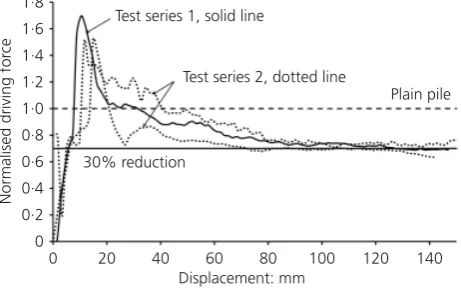
Figure 12 shows the normalised results of three separate experiments carried out to explore the effects of close rib spacings. Again, a high level of consistency was achieved between the results of all tests. The initial increased force required to penetrate the pile soon dissipated, and beyond 40 mm pile embedment a steady decrease in required driving force was observed. For the depth of penetration explored in the tests, which was constrained by the apparatus, a limiting reduction in driving force of approximately 30% was achieved. Both Figure 11 and Figure 12 appear to show a trend of reduced normalised driving force with increasing embedment depth and it may well be that further reductions in normalised driving could accrue if the piles were driven to a greater depth.
Following completion of the tests, the piles were removed from the model and it was consistently apparent that there was very little adhesion between the ribbed piles and the soil (see Figure 13) and only to some extent for the piles with driving shoes, in comparison with the plain pile which always needed to be washed to remove the adhered clay.
5. Discussion
Simple bearing capacity calculations, combined with some assumptions for adhesion between the pile and the clay, can be used to suggest an upper bound to the driving force required for the pile with a large toe. Similarly, a bearing capacity only
calculation can be used to give a lower bound for the pile with a small toe. Figure 14 shows the upper and lower bounds plotted with the average driving force required for each pile type. A value of 0.2 for adhesion between the plain pile and clay has been assumed. This value is quite low, but within recommended values for use in practice (Tomlinson, 1957). However, since the steel surfaces of the model piles were quite smooth in comparison to a real sheet pile this value is almost certainly justifiable and may even have been lower.
The results suggest that the driving force obtained from the pile tests comfortably sit within the theoretical bounds. Furthermore, the use of driving shoes appears to reduce the driving force required to somewhere near that of a theoretical pile, with driving resistance accruing from only bearing capacity.
From the driving forces measured in the tests and the observa-tion that soil was not generally found to have adhered to the pile surface when the model was dismantled, it is clear that both driving shoes and ribs can be effective in reducing driving forces. Much greater reductions were seen with driving shoes, indicating that only relatively minor modifications are necessary to gain significant benefit. It may be thought that the use of ribs is unnecessary if driving shoes are used. The initial increase in driving force observed in each test can be attributed to the larger shoe area. It should be considered that the tests at 20g explored the use of piles driven to a relatively shallow depth, about 3.5 m at prototype scale. While the wide (5 mm) driving shoe appeared to maintain a reduced normalised driving force for the full depth there is some indication that the smaller (3 mm) driving shoe may have reduced efficacy at greater depth. This is entirely reasonable and, given the fact that the size of the driving shoe on both piles was large in comparison with the size of shoe that may be regarded as realistic at prototype scale, suggests that driving shoes may have limitations.
Conversely, there is no indication that either wide- or narrow-spaced ribs suffered from reduced efficacy with greater depth of penetration. In fact, quite the opposite is suggested by Figures 9 and 10 in which there is a downward trend of normalised driving 0
0·2 0·4 0·6 0·8 1·0 1·2 1·4 1·6 1·8
0 20 40 60 80 100 120 140
Normalised driving for
ce
Displacement: mm Test series 1, solid line
Test series 2, dotted line
30% reduction
[image:8.595.318.554.141.243.2]Plain pile
Figure 12.Load–displacement graphs with close (10 mm) rib spacing normalised by the force required to drive the plain pile
[image:8.595.62.293.611.756.2]force. Tests in which piles could be driven to a greater depth would be needed to confirm this.
6. Conclusion
It is evident from the significant number of tests reported that reduced driving forces can be achieved by modifying both pile tip and the pile surface. The tests conducted involved individually driving modified sheet piles into a soil sample and comparing the driving forces needed to install the piles with that of an equiva-lent plain pile. The results that were obtained were consistent and they showed significant reduction in the driving forces, especially when driving shoes were used.
The driving forces for the modified piles were always greater than those of the control pile during the initial stages of the experiment; however, all of the modified piles showed a reduction in the driving force at greater depth when compared to the plain pile. Clay soils are often overlain with granular deposits; the effect of the overlying material compared with clay at the surface is likely to result in an increased driving force for piles with driving shoes. Increased driving force at shallow depth is not, however, considered problematic since, at this stage of driving, the machine has ample capacity to overcome the resistance. The effect in respect of pile damage, driving stress and pile deflection of driving a shoe and/or ribbed pile through a layer of coarse overburden material has not been investigated.
It should be noted that reductions in driving force were not of the same magnitude as those seen in field trials on tubular piles (Finlayet al., 2001) but this could possibly be explained, in part, by reduced adhesion in the model piles compared to the prototype used in the field trials.
Driving shoes appeared to give much greater reductions in
required driving force for the relatively shallow depths explored, but there remains doubt about the efficacy of driving shoes at greater depths since the normalised driving forces may show an increasing trend as the piles reach full penetration.
Modifications to the pile surface using ribs provide a significant, if modest, reduction in normalised driving force. The test results suggest that this is maintained over the full depth of penetration.
Furthermore, the test results may indicate that the normalised force required to penetrate piles with ribs is reduced with increasing embedment depth, suggesting that there may be more benefit accruing from deeply embedded piles.
The reported tests have successfully shown the technique’s ability to reduce the pile driving force. The tests were designed solely to monitor this; further work is required to explore the deflections associated with piles installed in this manner. The disturbance of soil in the passive zone is thought to be small and to have limited effect on wall deflection, although this has yet to be verified. Furthermore, the disturbance resulting from water jetting or pre-auguring is likely to be more severe. Further work is also required to optimise the pile rib and shoe geometry, as well as the rib spacing and distance to first rib.
Acknowledgements
The authors are grateful to the International Press-in Association and The Geotechnical Engineering Research Centre, City uni-versity for financial support for this project.
REFERENCES
Al-Tabbaa A(1987)Permeability and Stress–Strain Response of Speswhite Kaolin. PhD thesis, Cambridge University, Cambridge, UK.
0 500 1000 1500 2000 2500
0 20 40 60 80 100 120 140
Driving for
ce: N
Displacement: mm
Upper bound assuming bearing and friction for pile with large shoe Lower bound assuming only end bearing for pile with small shoe Average of large shoe tests
[image:9.595.135.468.136.329.2]Average of small shoe tests
Figure 14.Load–displacement for piles with driving shoes, also showing theoretical upper and lower bounds
Geotechnical Engineering
Volume 167 Issue GE1
Reducing driving forces for pressed-in piles
Craig WH(1995) Geotechnical centrifuges: past, present and future. InGeotechnical Centrifuge Technology(Taylor RN (ed.)). Blackie Academic and Professional, Glasgow, UK, pp. 1–17.
Finlay TCR, White DJ, Bolton MD and Nagayama T(2001) Press-in pilPress-ing: The Press-installation of Press-instrumented steel tubular piles with and without driving shoes.Proceedings of the 5th International Conference on Deep Foundation Practice, Singapore, pp. 199–208.
Gorasia RJ(2010)High Capacity Ribbed Pile Foundations in Stiff Clay. PhD transfer report, City University, London, UK.
Randolph MF and Houlsby GT(1984)The Limiting Pressure on a Circular Pile Loaded Laterally in Cohesive Soil. Cambridge University, Cambridge, UK, CUED/D-Soils TR147.
Stewart DP and Randolph MF(1991) A new site investigation tool for the centrifuge. InProceedings of Centrifuge ‘91(Ko HY (ed.)). Balkema, Rotterdam, the Netherlands.
Tomlinson MJ(1957) The adhesion of piles driven in clay soils.Proceedings of the 4th International Conference on Soil Mechanics and Foundation Engineering, vol. 2, pp. 66–71.
WHAT DO YOU THINK?
To discuss this paper, please email up to 500 words to the editor at [email protected]. Your contribution will be forwarded to the author(s) for a reply and, if considered appropriate by the editorial panel, will be published as a discussion in a future issue of the journal.