Ames Laboratory Technical Reports
Ames Laboratory
11-1959
An autographic elevated temperature creep testing
facility
Robert L. Hammel
Iowa State UniversityRobert E. Uhrig
Iowa State UniversityFollow this and additional works at:
http://lib.dr.iastate.edu/ameslab_isreports
Part of the
Materials Science and Engineering Commons
This Report is brought to you for free and open access by the Ames Laboratory at Iowa State University Digital Repository. It has been accepted for inclusion in Ames Laboratory Technical Reports by an authorized administrator of Iowa State University Digital Repository. For more information, please [email protected].
Recommended Citation
Hammel, Robert L. and Uhrig, Robert E., "An autographic elevated temperature creep testing facility" (1959).Ames Laboratory Technical Reports. 20.
An autographic elevated temperature creep testing facility
Abstract
The problems of obtaining accurate strain data, providing reliable temperature control, and affording oxidation protection arise in the experimental determination of the elevated temperature creep properties of materials. The apparatus described in this paper provides an autographic strain record using commercially available equipment, reliable temperature control for both constant or programmed cyclic temperatures , and oxidation protection by means of specimen encapsulation.
Disciplines
Materials Science and Engineering
AN AUTOGRAPHIC ELEVATED TEMPERA ... r~·~~:-~:;,~'\t~<~;
TURE CREEP TESTING FACILITY by
UNCLASSIFIED
1
S-
·6b
/
~:qtq '-'!:I.( ~Jt. ;\~i·:·th--..'-dq ;.lnd -~r('f_-hr-:.1rp1.:.· :: (tJC'"- -~8)
TlD-:i:SOO. Anc:u~l 1, lqo;·~
UNITED STATES ATOMIC ENERGY COMMISSION
Research and Development Report
AN AUTOGRAPHIC ELEVATED TEMPERA-TURE CREEP TESTING FACILITY
by
Robert L. Hammel and Robert E. Uhrig
November 1959 .
Ames Laboratory at
Iowa State University of Science & Technology F. H. Spedding, Director
Contract W -7405 eng-82
2 IS-66
This report is distributed according to the category Equipment, Methods,
and Techniques (UC-38) as listed in TID-4500, August l, 1959.
Legal Notice
This report was prepared as an account of Government sponsored work.
Neither the United States, nor the Commission, nor any person acting on
behalf of the Commission:
A. Makes any warranty of representation, express or implied,
with respect to the accuracy, completeness, or usefulness of
the information contained in this report, or that the use of
any information, apparatus, method, or process disclosed in
this report may not infringe privately owned rights; or
B. Assumes any liabilities with respect to the use of, or for
damages resulting from the use of any information, apparatus
method, or process disclosed in this report.
As used in the above, "person acting on behalf of the Commission"
in-cludes any employee or contractor of the Commission, or employee of such
contractor, to the extent that such employee or contractor of the Commission, or employee of such contractor prepares, disseminates, or provides access to, any information pursuant to his employment or contract with the Commission, or his employment with such contractor.
Printed in USA. Price
$ 0.
75
Available from the-Office of Technical Services
U.S. Department of Commerce
IS-66
CONTENTS
ABSTRACT . . . • . . . • . . ..
IITTrt·.~ Df_iC'J'I.: I··i •• • •• •
SYSTEiVlS . • . • . . . • .
I. Load Application
II. Strain Measurement and Recording.
III. Heating and Teinperature Control .
IV. Temperature Measurement and Recording . •
V. Oxidation Protection.
CONCLUSIONS . . . • . . • .
3
5
8
8
8
16
18
18
IS-66
AN AUTOGRAPHIC ELEVATED TEMPERATURE CREEP
TESTING F AGILITY
by
Robert L. Hammel and Robert E. Uhrig
5
Abstract--The problems of obtaining accurate strain data, providing reliable
temperature control, and affording oxidation protection arise in the experimental
determination of the elevated temperature creep properties of materials. The
apparatus described in this paper provides an autographic strain record using
commercially available equipment, reliable temperature control for both
con-stant or prograrrm.ed cyclic temperatures, and oxidation protection by means
of specimen encapsulation. ( 1 )
INTRODUCTION
The problems normally associated with elevated temperature creep testing
are obtaining accurate strain data, providing reliable temperature control and
affording oxidation protection.
Investigators have measured the strain in a creep test by a variety of
methods. Often these methods have involved considerable chance for human
error and required specially trained personnel. To avoid such problems, a
standard commercial follow-up contact type extensometer is used to measure
6
strip chart as the temperature. This method greatly simplifies the task of
obtaining creep data, gives a continuous record of strain, and permits ready inspection of the strain rate as the test progresses.
Since creep is highly temperature sensitive, precise temperature control
is necessary. Small temperature variations can markedly alter the strain rate;
thus the temperature controller must be reliable with high sensitivity for
extended periods of time. This type of temperature control is provided by an
electronic proportioning controller which utilizes one leg of an electronic bridge
''"
circuit as the temperature sensing element~"' In order to study the effects of
temperature oscillation, the controller can also produce a programmed cyclic
variation. This controller has provided the desired temperature condition
within
.2:
1oc
for periods up to 500 hours.Large and cumbersome vacuum or inert gas systems are commonly employed
to provide oxidation protection. Here oxidation protection is afforded by a
simple yet highly effective technique of specimen encapsulation in bellows,
which eliminates the large protective system and thus permits greater flexibility
in the use of commercially available testing equipment.(!)
GENERAL DESCRIPTION
A general view of two test units with the major components labeled is
shown in Fig. 1. Each unit consists of a 12, 000 lb. lever arm creep machine,
·a two .. pen strip chart recorder, a multiple-point strip chart temperature recorder,
A
..
Fig.
1
-General
view
A.
Protective
hood
C.
Furnace
"'I
B.
Creep
machine
D.
Two-pen
recorder
E.
Furnace
8
provide the necessary systems for load application, strain measurement and
recording, heating and temperature control, and temperature measurement
and recording. Each system will be discussed in turn.
The protective hood shown in Fig. 1 on one creep machine prevents room
temperature convection currents from affecting the furnace temperature and
extensometer. Prior to the use of the hoods, the air currents disturbed the
consistency of the strain measurement by causing irregular thermal variations.
I. Load Application
The specimen is stressed by means of dead weights hung on the lever arm
of the creep machine. A sdssors-type jack is used to support the weights and
lever arm while the temperature condition is achieved. Lowering the jack
pro-vides a single, shock free loading within a few seconds. Prior straining .of
the specimen due to the machine tare or incremental loading of the weights is
avoided.
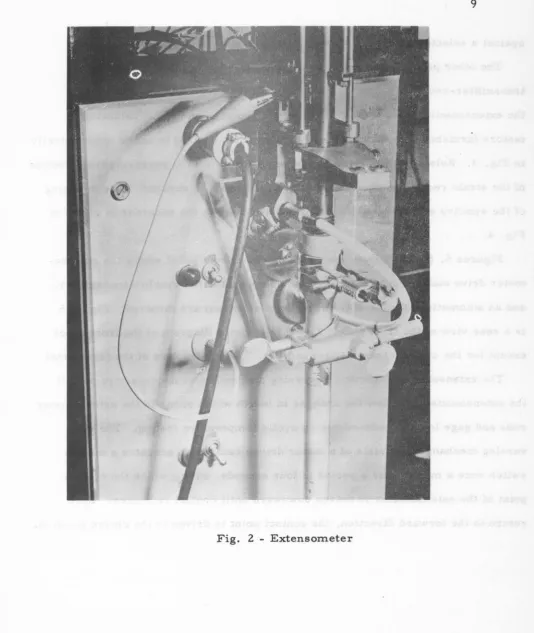
II. Strain Measurement and Recording
The follow-up contact type extensometer which measures the strain is
shown in Fig. 2. The extensometer is attached to the shoulders of the specimen
through two sets of contact points set at right angles to each other.
To obtain a simultaneous autographic record of strain and temperature vs.
time, both quantities are transmitted to a strip chart recorder. A Leeds
and Northrup two-pen recorder was selected as being most adaptable for tlilis
purpose. One pen of this recorder utilizes the standard potentiometer circuit
9
[image:12.598.54.589.83.717.2]10
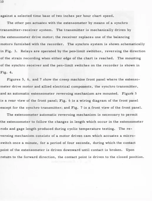
against a selected time base of two inches per hour chart speed.
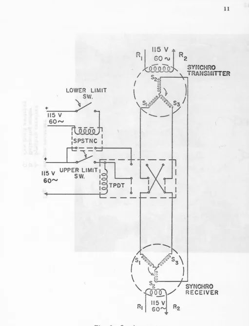
The other pen actuates with the extensometer by means of a synchro
transmitter-receiver system. The transmitter is mechanically driven by
the extensometer drive motor; the receiver replaces one of the balancing
motors furnished with the recorder. The synchro system is shown schematically
in Fig. 3. Relays are operated by the pen-limit switcme:s, reversing the direction
of the strain recording when either edge of the chart is reached. The mounting
of the synchro receiver and the pen-limit switches on the recorder is shown in
Fig. 4.
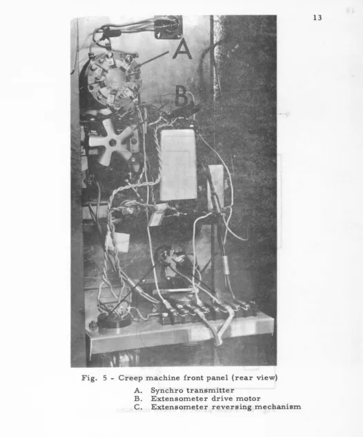
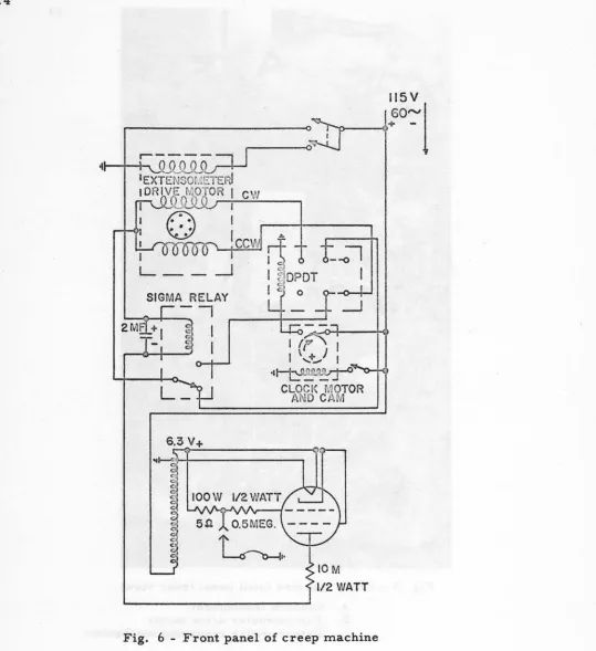
Figures 5, 6, and 7 show the creep machine front panel where the extenso
-meter drive motor and allied electrical components, the synchro transmitter,
and an automatic extensometer reversing mechanism are mounted. Figur!e 5
is a rear view of the front panel; Fig. 6 is
a:
wiring diagram of the front panelexcept for the s,ynchro transmitter; and Fig. 7 is a front view of the front panel.
The extensometer automatic reversing mechanism is necessary to permit
the extensometer to follow the changes in length which occur in the extensometer
rods and gage length produced during cyclic temperature testing. The
re-versing mechanism consists of a motor driven cam which accuates a
micro-switch once a minute, for a period of four seconds, during which the contact
point of the extensometer is driven downward until contact is broken. Upon
[image:13.591.15.533.73.755.2]LOWER
LIMIT
sw.
~
115v
60"'
I ... .._.._..._,
:sPSTNC
+__r:y-:;;
o - + -_ ____,_+
UPPER LIMIT
1115 V
S
W.
I60"'
I
I
Fig. 3 - Synchro system
[image:14.594.65.576.69.737.2]Fig.
4
-Two-pen
recorder
A.
Synchro
receiver
B.
Balancing
motor
C.
Pen
limit
switches
13
Fig. 5 - Cr·eep machine front panel (rear view)
A. Synchro transmitter
B. Extensometer drive motor
[image:16.594.60.586.61.692.2]14
SIGMA
-,
RELAY
'----<>--+--2M
I
I
I /f'I \
...
+ .. ) I··
~
CLOCI~~
f;,.WTORAND CAM
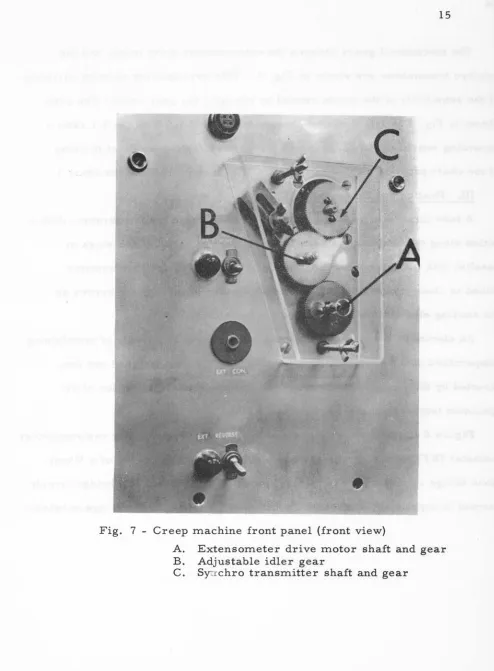
[image:17.595.22.561.75.664.2]15
B
Fig. 7 - Creep machine front panel (front view}
A. Extensometer drive motor shaft and gear
B. Adjustable idler gear
[image:18.592.80.575.73.745.2]16
The mechanical gears between the extensometer drive motor and the
synchro transmitter are shown in Fig. 7. This arrangement permits variation
of the sensitivity of the strain record by changing the gear ratio. The ratio
shown in Fig. l is 1: 1; it can be changed to 1:2 or 2: 1. With the l: l ratio a
recording sensitivity of 12. 31 micro inches/inch for the smallest division
of the chart paper is obtained. (1 div. = l/10 inch or l0°C on the chart.)
III. Heating and Temperature Control
A tube furnace is used to heat the specimen where the temperature
distri-bution along the heat zone is adjusted by means of variable resistors in
parallel with the furnace windings. A platinum resistance thermometer
wound in close proximity with the middle winding of the furnace serves as
the sensing element for the temperature controller.
An electronic proportioning temperature controller capable of maintaining
temperature at the sensing element within 0. 02°C, was designed and
con-structed by the Arne s Laboratory. (2 ) In this application, variation of the
specimen temperature does not exceed± 1 °C.
Figure 8 shows a block diagram of the heating system. The resistance
ther-mometer (RT), which serves as the sensing element, is one leg of a
Wheat-stone bridge c~rcuit. It is an integral part of the furnace. The bridge circuit
OSCILLATOR
a
POWER AMPLIFIER Rh.s I ;> R1 . R2 RT?S
I?~ . 0"1
R3t
1•
~~
<
Rh NARROW BAND AMPLIFIER PHASESENSITIVE DETECTOR
18
is fed to a high gain, narrow-band amplifier and then to a phase sensitive detector
which in turn contr·ols the d. c. power amplifier. The d. c. amplifier regulates
the current in the d. c. winding of the saturable core reactor. The a. c.
windings of the reactor are in series with the line and furnace windings.
The addition of the sine function potentiometer between the bridge and
narrow-band amplifier, provides a programmed sinusoidal temperature variation.
The amplitude and frequ,ency are limited only by the ability of the furnace to
respond to the controller current. With the furnace currently being used,
fre-quencies up to five cycles per hour with amplitudes from SPC to 35°C are
possible.
Eig13-re 9 shows the schematic circuit diagram of the controller.
IV. Temperature Measurement and Recording
Standard equipment and techniques are used for temperature measurement
and recording. Chromel-al\lmel thermocouples are employed exclusively.
The test temperature is recorded as a continuous function on the same time
base as the strain record by the two-pen strip chart recorder ( as discussed
in Section II). To provide a means of determining the temperature distribution
along .the gage length, a multiple point recorder is used to measure and
con-tinuously record the temperatures at six points along the specimen.
V. Specimen Encapsulation
When necessary, protection of the specimen from oxidation is provided
3A
115V so-
~
rn:
TO 6SJ7 ...-REG B +
~ ~-:~".?
_t3
75
K
450V
'='
~PILOT ~LIGHT
C-17ZI 8.5H ~ l"1fW
f:Sy~·s ~-REGS+
j-16 c,;oov
M-SOO SILICON DIODES
.
_
-._-..
-~IiiJ
22.5K lOW
3-6Y6'S
IM
HEATER ELEMENT
68
K
I
K
t1
2!1K
1000-390K
680
K
500
,.,.,
e
o.l
~~c~v;
~
6
6SC7
ISO~
75 K
-r
40
4i'~
l4sov :l>ICSW 40 450j v
~ Jil6 .l"S T-4501/f-450V -zsv e :¥"450V~
ZOK zw 33K zw
8.2K IW
Fig.
9
4~V 3.3K
33K
lOOK 0.02
6H6
I
® NOTE 0.1 = Slt--
5K 2WSl 318K 318 K ALL RESISTANCE IN OHMS 1/2 WATT ALL CAPACITANCE IN MICROFARADS UNLESS SPECIFIED
I
%;£'10.~"';2
5K -20K 6C4 QOIIBK 1as
470K
..-.-.
~ GRID 500 500 CATH. ,..~1 ~;4-f 1000-OSC. "TEE"5K 3W
~
l
6V6
•
MERIT
.§
;~~~j;
.•
6V6I
MF-141I
MODEL 2 FURNACE CONTROLLER 220V. FURNACE SINUOSOIDAL VARYING AMES LABORATORY OF ATOMIC ENERGY COMMISSION IOWA STATE UNIVERSITY AMES IOWA20
of oxidation protection has the advantages of allowing the conventional furnace
and extensometer to be used, and provides a highly reliable system for extended
periods of time.
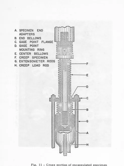
As shown in Fig. 10, the assembly consists of four machined fittings and
three flexible bellows, which are positioned on the specimen as shown in Fig. 11.
The assembly is sealed in an argon-filled welding chamber where the butted
flanges between the machined fittings and the bellows are welded together.
The welding technique and the equipment used are described by Bohn, Uhrig
and Murphy. {l)
Application of the encapsulation technique does require the test temperature
be measu:r;ed on the outer surface of the assembly. A special assembly in
which thermocouple leads were brought outside the bellows through kovar seals,
was fabricated to determine the correlation between the specimen and outer
capsule temperatures. It was found that the temperature on the surface of the
specimen was within the range of the temperature distribution measured along
the specimen gage length on the outside of the assembly. At 800°C this range
CONCLUSIONS
The test facility described provides several definite advantages. The
autographic strain record greatly simplifies the task of gathering creep
information, and provides a record of the entire strain history. This has
Fig.
10
-Build
up
of
encapsulated
specimen
22
A. SPECIMEN END
ADAPTERS B. END BELLOWS
C. GAGE POINT FLANGE D. GAGE POINT
MOUNTING RING E. CENTER BELLOWS
F.
CREEP SPECIMENG. EXTENSOMETER , RODS
H. CREEP LOAD ROD
1n----G
[image:25.597.38.532.55.715.2]23
The controller is adaptable for cyclic temperature output, providing a high
degree of temperature control under constant or cyclic conditions.
Use of the encapsulation technique to prevent specimen oxidation, as applied
to creep, permits greater flexibility in other components of the test unit by
eliminating elaborate vacuum or inert gas systems. It provides highly reliable
protection for extended periods of time and is not subject to equipment failure ,
which can occur when more complex systems must be relied upon for prolonged
intervals.
REFERENCES
(1) Bohn, J. R., Uhrig, R. E., and Murphy, Glenn. A method for protection
of high temperature creep specimens. AEC Report No. IS-48 (Iowa State
University). 1959.
(2) Svec:, H. J., Read, A. A., and Hilker, D. W. A porportioning furnace
temperature controller. AEC Report No·. ISC-585 (Iowa State University)~