FORMULATION AND IN-VITRO EVALUATION OF
5-FLUOROURACIL MICROCAPSULES BY USING DIFFERENT
METHODS OF MICROENCAPSULATION
A dissertation Submitted toThe Tamil Nadu Dr. M.G.R. Medical University
Chennai - 600 032
In partial fulfillment for the award of Degree of
MASTER OF PHARMACY (Pharmaceutics)
Submitted by
SRIKANTH REDDY JEDDIPELLY
(Register No: 26116012)Under the Guidance of
Dr. S.SHANMUGAM, M. Pharm
., Ph.D.Professor, Department of Pharmaceutics
ADHIPARASAKTHI COLLEGE OF PHARMACY
(ACCREDITED BY “NACC” WITH A CGPA OF 2.74 ON A FOUR POINT SCALE AT “B” GRADE)
This is to certify that the research work entitled “FORMULATION AND INITRO EVALUATION OF 5-FLUOROURACIL MICROCAPSULES BY
USING DIFFERENT METHODS OF MICROENCAPSULATION” submitted to The Tamil Nadu Dr.M.G.R. Medical University, Chennai in partial fulfillment for the
award of the Degree of the Master of Pharmacy (Pharmaceutics) was carried out by
“SRIKANTH REDDY JEEDIPELLY” (Register No. 26116012) in the Department of Pharmaceutics under my direct guidance and supervision during the academic year 2012-2013.
Place:Melmaruvathur Prof. (Dr.) S.SHANMUGAM, M. Pharm., Ph.D.
Date: Department of Pharmaceutics, Adhiparasakthi College of Pharmacy,
This is to certify that the dissertation entitled “FORMULATION AND IN-VITRO EVALUATION OF 5-FLUOROURACIL MICROCAPSULES BY USING
DIFFERENT METHODS OF MICROENCAPSULATION” the Bonfide research work carried out by “SRIKANTH REDDY JEDDIPELLY” (Register No. 26116012) in the Department of Pharmaceutics, Adhiparasakthi College of Pharmacy, Melmaruvathur which is affiliated to The Tamil Nadu Dr. M.G.R. Medical University, Chennai, under the guidance of Dr.S.SHANMUGAM, M.Pharm.,Ph.,D. Department of Pharmaceutics, Adhiparasakthi College of Pharmacy, during the academic year 2012-2013
Place: Melmaruvathur Prof. (Dr.) T. VETRICHELVAN, M. Pharm., Ph.D., Date: Principal,
Dedicated
To
ACKNOWLEDGEMENT
First and foremost, I wish to express my deep sense of gratitude to His
Holiness ARULTHIRU AMMA for his ever growing blessings in each step of the
study.
I wish to express my sincere thanks to our respected Vice-President,
THIRUMATHI V. LAKSHMI BANGARU ADIGALAR, ACMEC Trust,
Melmaruvathur, for her excellence in providing skillful and compassionate spirit of
unstinted support for carrying out this research work.
I would like to thank God for showing his blessings upon me by providing me
this opportunity to excel one step further in life.
I consider myself to be very fortunate to have, Prof. Dr. S.SHANMUGAM,
M.Pharm., Ph.D. Department of Pharmaceutics, Adhiparasakthi College of
Pharmacy, and Melmaruvathur, as Guide, who with his dynamic approach boosted my
moral, which helped me to a very great extent in the completion of this dissertation.
His assurances and advice had helped me in good stead. His guidance, support,
enthuses and encouragement, which made the dissertation an educative and
interesting experience. I am in short of words to thank him for unlimited patience,
freedom of thought, faith and affection bestowed upon me throughout my project
work.
I wish to extend my sincere thanks to Prof.Dr.T.VETRICHELVAN,
M.Pharm., Ph.D., Principal, Adhiparasakthi College of Pharmacy, Malmaruvathur,
for providing invigorating and conductive environment to pursue this research work
M.Pharm, Mr. T. AYYAPPAN, M. Pharm., Assistant Professor, other teaching
staff and the non-teaching staff Mrs.S. KARPAGAVALLI, D. Pharm.,
Mr. M. GOMATHI SHANKAR,D. Pharm., Mrs.DHAKSHYANAI, D. Pharm.,
for their valuable help and guidance during the course of my research work.
I am very grateful to our Librarian Mr. M.SURESH, M.L.I.S., for his kind
co-operation and help in providing all reference books and literatures for the
completion of this project.
I thank to RAJYALAKSHMI for her kind obligation in procuring gift
sample of 5-fluorouracil. KRANTHI NAKARAKANTI for his king obligation in
procuring gift sample of polymers gelatin and sodium alginate
I am very thankful to SOWJANYA.M for providing all facilities and
assistance during preparation of microcapsules and helping me to find out the
literature review and completion of my project without any disturbances.
I am very thankful to IDEAL ANALYTICAL LAB, Pondicherry and
P.S.G COLLEGE OF PHARMACY, Peelamedu. For helping me in the completion
of preformulation studys and evaluations of microcapsules.
I am very grateful Balaji computers and Star xerox, for their kind
co-operation and help during the typing work of whole dissertation book.
I am thankful to my colleague, my dear friends, for being a great source of
help whenever I needed and for sharing their ideas and extending support during the
course of study.
Finally, I can hardly find any words enough to express gratitude to
My Parents, my ever loving, affectionate Family members especially sisters,
without which it would have been impossible for me to achieve this success.
Above all “Thank you” to the Almighty, who has given me this opportunity to
extend my gratitude to all those people who have helped me and guided me
throughout my life. I bow my head in complete submission before him for the
blessings poured on me.
Chapter
Title
Page
No.
1 INTRODUCTION 1-33
2 AIM AND OBJECTIVES 34-35
3 PLAN OF WORK 36-37
4 LITERATURE SURVEY
4.1. Literature review 38-43
4.2. Drug Profile 44-46
4.3. Polymers and Excipients Profile 47-57
5 MATERIALS AND EQUIPMENTS 58-59
5.1.Materials used 58
5.2. Equipments used 59
6 PRE-FORMULATION STUDIES 60-63
6.1. Characterization of Drug 60
6.2. Drug-Polymers Compatibility Studies 63
7 FORMULATION OF 5-FLUOROURACIL
MICROCAPSULES 64
8 EVALUATION OF 5-FLUOROURACIL
MICROCAPSULES 65-70
8.1 Organoleptic properties 66
8.2.Evaluation of microcapsules 66
8.3. In-vitro drug release studies 68
8.4. Release drug data model fitting 69
9 RESULTS AND DISCUSSION 71-116
9.1. Characterization of Drug 71
9.2. Drug-Polymers Compatibility Studies 81
9.3 Organoleptic properties of microcapsules 87
9.4. Evaluation of Microcapsules 89
9.5. In-vitro drug release studies 93
9.6.Release drug data model fitting 103
9.7. Stability Studies 110
10 SUMMARY AND CONCLUSION 117-118
11 FUTURE PROSPECTS 119
Table No.
Name of Table
Page
No.
4.1 Uses of sodium alginate 53
4.2 Uses of ethyl cellulose 57
5.1 List of materials and their suppliers 58
5.2 List of equipments with their make and model 59
7.1 Composition of 5-fluorouracil microcapsules 64
8.1 Parmeters for In-vitro drug release 68
9.1 Solubility of 5-fluorouracil in different solvents 71
9.2 Concentration and Absorbance data for Calibration Curve of
5-fluorouracil in methanol 73
9.3 Data for Calibration Curve parameters of 5-fluorouracil in
methanol 74
9.4 Concentration and Absorbance data for Calibration Curve of
5-fluorouracil i n 0.1N HCl 75
9.5 Data for Calibration Curve parameters of 5-fluorouracilin 0.1N
HCl 76
9.6 Concentration and Absorbance data for Calibration Curve of
5-fluorouracil in Phosphate buffer pH 6.8 77
9.7 Data for Calibration Curve parameters of 5-fluorouracil in
Phosphate buffer pH 6.8 78
9.8 Characteristic Frequencies in IR Spectrum of 5-fluorouracil 80
9.9 Loss on drying of 5-fluorouracil 80
9.10 General appearance study 87
9.11 Particle size of various formulations of microcapsules 88
9.12 Physico-Chemical properties of microcapsules 89
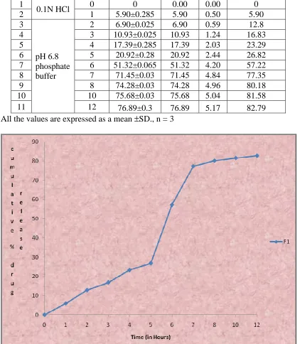
9.13 In-vitro drug release data of Formulation F1 93
9.14 In-vitro drug release data of Formulation F2 94
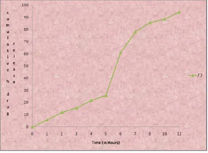
9.15 In-vitro drug release data of Formulation F3 95
9.16 In-vitro drug release data of Formulation F4 96
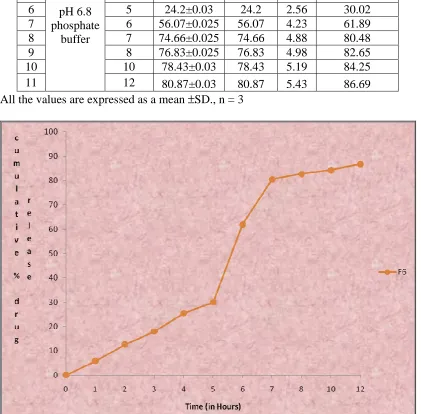
9.17 In-vitro drug release data of Formulation F5 97
9.20 In-vitro drug release data of Formulation F8 100
9.21 In-vitro drug release data of Formulation F9 101
9.22 Different Kinetic models for Formulations F1-F9 104
9.23 Drug content of formulation F9 at the end of 1 month of stability 110
9.24 In-vitro drug release data of formulation F9 at the end of 1 month
of stability 111
9.25 Drug content of formulation F9 at the end of 2 months of stability 112
9.26 In-vitro drug release data of formulation F9 at the end of 2 months
of stability 113
9.27 Drug content of formulation F9 at the end of 3 months of stability 114
9.28 In-vitro drug release data of formulation F9 at the end of 3 months
Figure
No.
Name of Figure
Page
No.
1.1 Schematic representation diffusion sustained drug release reservoir
system 11
1.2 Schematic representation diffusion sustained drug release matrix
system 13
1.3 Microsphere and microcapsule 17
1.4 Coacervation process 22
a) Core material dispersion in solution of shell polymer 22
b) Separation of coacervate from solution 22
c) Coating of core material by micro droplet of coacervate 22
d) Coalescence of coacervate to form continous shell around
core particles 22
1.5 Mechanism of solvent evaporation method 25
1.6 Spray dryer 28
1.7 Representation of typical pan coating 29
1.8 Applications of microencapsulation 32
9.1 Absorption maximum of 5-fluorouracil in water 72
9.2 Calibration curve of 5-fluorouracil in water 73
9.3 Absorption maximum of 5-fluorouracil in 0.1N HCl 74
9.4 Calibration curve of 5-fluorouracil in 0.1N HCl 75
9.5 Absorption maximum of 5-fluorouracil in Phosphate buffer pH 6.8 77
9.6 Calibration curve of 5-fluorouracil in Phosphate
buffer pH 6.8 78
9.7 IR Spectrum of 5-fluorouracil 79
9.8 FTIR spectrum of fluorouracil 81
9.11 FTIR spectrum of fluorouracil and ethylcellulose 84
9.12 DSC of 5-fluorouracil 85
9.13 DSC of 5-fluorouracil and sodium alginate 85
9.14 DSC of 5-fluorouracil and gelatin 86
9.15 DSC of 5-fluorouracil and ethyl cellulose 86
9.16 Paricle size estimation by using phase contraction microscopy 88
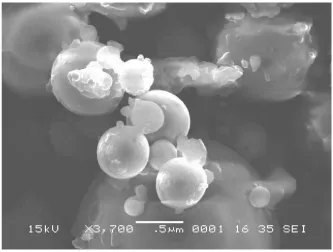
9.17 Scanning electron microscopy of best formulation 90
9.18 Particle size distribution by using Malvern system 91
9.19 Zeta potential of formulation by using Malvern system 92
9.20 Cumulative percentage drug release profile of formulation F1 93
9.21 Cumulative percentage drug release profile of formulation F2 94
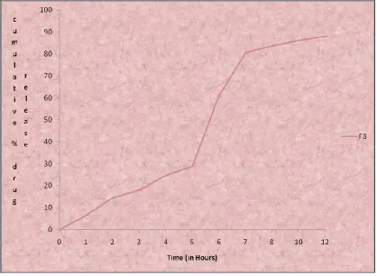
9.22 Cumulative percentage drug release profile of formulation F3 95
9.23 Cumulative percentage drug release profile of formulation F4 96
9.24 Cumulative percentage drug release profile of formulation F5 97
9.25 Cumulative percentage drug release profile of formulationF6 98
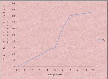
9.26 Cumulative percentage drug release profile of formulation F7 99
9.27 Cumulative percentage drug release profile of formulation F8 100
9.28 Cumulative percentage drug release profile of formulation F9 101
9.29 Cumulative percentage drug release profile of formulation F1-F9 102
9.30 Higuchi plot of formulation F1 105
9.31 Higuchi plot of formulation F2 105
9.32 Higuchi plot of formulation F3 106
9.33 Higuchi plot of formulation F4 106
9.36 Higuchi plot of formulation F7 108
9.37 Higuchiplot of formulation F8 108
9.38 Higuchi plot of formulation F9 109
9.39 In-vitro drug release profile of formulation F9 at the end of 1 month
of stability 111
9.40 In-vitro drug release profile of formulation F9 at the end of 2
months of stability 113
9.41 In-vitro drug release profile of formulation F9 at the end of 3
months of stability 115
9.42 Comparisons of % drug content for formulation F9 with initial and
different periods of stability 116
9.43 Comparisons of Cumulative % drug released at the end of 12 hours
% ---- Percentage
< ---- Less Than
> ---- More Than
°C ---- Degree Celsius
µg ---- Microgram
cm ---- Centimeter
DE ---- Dissolution Efficiency
DSC ---- Differential Scanning Calorimetry
F ---- Formulation
FTIR ---- Fourier Transform-InfraRedSpectroscopy
GIT ---- Gastrointestinal Tract
gm ---- Grams
HCl ---- Hydrochloric acid
HPMC ---- Hydroxypropyl methylcellulose
hrs ---- Hours
ICH ---- International Conference on Harmonization
IP ---- Indian Pharmacopoeia
MDT ---- Mean Dissolution Time
mg ---- Milligram
ml ---- Milliliter
mm ---- Millimeter
NSAID ---- Non-Steroidal Anti-Inflammatory Drugs
PBS ---- Phosphate Buffer Solution
RH ---- Relative Humidity
rpm ---- Revolutions per Minute
S. No. ---- Serial Number
SEM ---- Scanning electron microscope
T ---- Time
USP ---- United State Pharmacopoeia
UV ---- Ultra Violet
W/v ---- weight/volume
ADHIPARASAKTHI COLLEGE OF PHARMACY,MELMARVATHUR. Page 1
1. INTRODUCTION
(Khachane K.N. et al.. 2011, Shalin A. Modi, et al..2011)
Oral route has been one of the most popular routes of drug delivery dueto its
easeof administration, patience compliance and least sterility constraints and flexible
design of dosage forms. Time release technology, also known as sustained-release
(SR), sustained-action (SA), extended-release(ER), time-release ortimed-release,
controlled-release(CR), modifiedrelease (MR) or continuous-release (CR), is a
mechanism used in pill tablets or capsules to dissolve slowly and release a drug
overaprolong period oftime. Different polymers are employed dueto their insitugel
forming characteristics and their ability to release entrapped drug in the specific
medium by swelling and cross-linking. Hydrophilic polymer matrix is widely used for
formulating an SRdosageform. Because of increased complication and expense
involved in marketing of newdrug entities, has focused greater attention on
development of sustained release or controlled releasedrug delivery system. Matrix
system is widely used for the purpose of sustainedrelease. Infact, a matrix is defined as
a well-mixed composite of one or more drugs with gelling agent i.e. hydrophilic
polymers. By the sustained release method therapeutically effective concentration can
be achieved in the systemic circulation over an extended period of time, thus
achieving better compliance of patients. Sustained release dosage forms are prepared
by coating the tablets so that the rate of solubility is controlled or individual
encapsulating microparticles of varying size sothat the rate of dissolution can be
controlled. With the development of modern synthetic ion exchange resins,
pharmaceutical industry adapted the i o n exchange technology to achieve sustained
ADHIPARASAKTHI COLLEGE OF PHARMACY,MELMARVATHUR. Page 2
1.1 Concept of Sustained Release (SR): (Kranthi Kumar Kotta.et al..2010)
The object of sustain release of drugs, in a general way is to modify the normal
behavior of the drug molecule in physiological environment. The following are the
benefits of sustained release formulations.
1. Sustained action at predetermined rate by maintaining a relatively constant,
effective drug level in the body with minimum side effects
2. Localization of drug action by special placement of a controlled release
systems usually rate controlled adjacent to or in diseased tissue of organ.
3. Targeting drug action by using or chemical derivatives to deliver drug to
particular target cell type.
1.1.1 Sustained release drug delivery system: (Remington., 2002)
Non immediate release drug delivery system may be conveniently divided into four
categories.
i. Delayed release
ii. Sustained release
a. Controlled release
b. Prolonged release
iii. Site specific release
iv. Receptor release
Sustained release system is a drug delivery that achieves release of drug over an
extended period of time. If the system is successful at maintaining controlled drug
level in the blood, it is considered as a controlled release system. If it is unsuccessful
but extends the duration of action over that achieved by conventional delivery it is
ADHIPARASAKTHI COLLEGE OF PHARMACY,MELMARVATHUR. Page 3
1.1.2 Advantages of Sustained Release Formulations (Sharma Nk., 1998)
1. Overcome patient compliance problems.
2. Minimize or eliminate systemic side effects by reduced fluctuation in drug level.
3. Minimize drug accumulation with chronic dosing.
4. Improve efficiency in treatment
a) Cures or controls disease condition more promptly.
b) Improves therapy and reduce the undesirable side effect by maintains the drug
level in plasma for prolonged period of time.
c) Improves bioavailability of some drugs.
5. Economy i.e. reduction in health care costs. The average cost of treatment over an
extended time period may be less.
6. Reduce dose frequency
7. Reduce fluctuations in blood levels
1.1.3 Disadvantages of Sustained Release Formulations:
1) Decreased systemic availability in comparison to immediate release conventional
dosage forms, which may be due to incomplete release, increased first-pass
metabolism, increased instability, insufficient residence time for complete
release, site specific absorption, pH dependent stability etc.
2) Poor in vitro – in vivo correlation.
3) Retrieval of drug is difficult in case of toxicity, poisoning or hypersensitivity
reactions.
4) Reduced potential for dose adjustment of drugs normally administered in varying
ADHIPARASAKTHI COLLEGE OF PHARMACY,MELMARVATHUR. Page 4
1.1.4 Classification of sustained release delivery system:
1. Rate program drug development systems
2. Activated modulated drug development systems.
3. Feed base modulated drug development systems.
4. Site targeting drug development
All categories consist of common structural features.
i. Drug reservoir compartment
ii. Rate controlling element
iii. Energy source
1.1.5 Attributes of drug candidates for sustained release systems:
There are specific attributes that a drug must possess for being suitable for
incorporation in sustained release systems.
1. The drug must be effective in a relatively small dose or else the large dose
required will make the preparation difficult to swallow.
2. Drugs with very short biological half life (less than 2 hrs) such as levodopa,
penicillin G, and furosemide require relatively large dose for incorporating in
sustain Release systems. His renders the dosage form very difficult to swallow.
3. Drugs with long biological half live (more than8 hrs) inherently or sustain release
and thus are viewed as questionable candidates for sustained release formulations.
4. Absorption of poorly water soluble drugs is often limited by dissolution rate.
Incorporation of such drugs into sustained release formulations is therefore
unnecessary and is likely to reduce the overall absorption efficiency.
5. Very insoluble drugs whose availability is controlled by dissolution (example
griseofulvin) may not benefit from this, since the amount of drug available for
ADHIPARASAKTHI COLLEGE OF PHARMACY,MELMARVATHUR. Page 5
6. Drugs with narrow requirement for absorption (e.g. drugs dependent on position
in the GI tract for optimum absorption) are also poor candidates for oral sustained
release formulations, since absorption must occur throughout the length of the gut.
E.g. vitamin C is absorbed preferentially from the upper portion of the intestine
and therefore it’s sustain release formulation are of questionable therapeutic value.
7. Before proceeding with the design of sustained release form of an appropriate
drug, the formulated should have an understanding the pharmacokinetics of the
candidate, should be that pharmacologic effect can be positively correlated with
drug blood levels, and should be knowledgeable about the therapeutic dosage,
including the minimum effective and maximum safe doses.
Although the above characteristic are useful rules of thumb for deciding whether or
not particular drug should be considered for sustained release drug delivery system,
there are several exceptions biological half life of nitroglycerin is less than 0.5hrs. it is
rapidly metabolized in liver and is poorly absorbed orally. However, sustain release
oral nitroglycerin obtained from these products provide adequate prophylaxis against
anginal attacks but are inadequate to treat acute anginal episodes.
1.2 Factors Influencing the Design and Performance of Sustained Release
Products: (Bramhankar and Jaiswal, 1995)
The type of delivery system and route of administration of the drug presented
in sustained drug delivery system may depend upon two properties They are
I. Physicochemical Properties of drugs
ADHIPARASAKTHI COLLEGE OF PHARMACY,MELMARVATHUR. Page 6
1.2.1 Physicochemical Properties of Drugs (Shalin A. Modi, et al..2011)
1. Dose size:
If an oral product has a dose size greater that 0.5gm it is a poor candidate for sustained release system, Since addition of sustaining dose and possibly the sustaining mechanism will, in most cases generates a substantial volume product that unacceptably large.
2. Ionization, PKa and Aqueous Solubility:
The pH Partition hypothesis simply states that the unchanged form of a drug
species will be preferentially absorbed through many body tissues. Therefore it is
important to note the relationship between thePKa of the compound and its
absorptive environment. For many compounds, the site of maximum absorption will
also be the area in which the drug is least soluble.
3. Partition coefficient:
The compounds with a relatively high partition coefficient are
predominantly lipid soluble and easily penetrate membranes resulting high
bioavailability. Compounds with very low partition coefficient will have difficulty in
penetrating membranes resulting poor bioavailability. Furthermore partitioning effects
apply equally to diffusion through polymer membranes.
4.Drug Stability: (Asija Rajesh, et al.. 2012, Shalin A. Modi, et al..2011)
In general the drugs, which are unstable in GIT environment poor candidates for
ADHIPARASAKTHI COLLEGE OF PHARMACY,MELMARVATHUR. Page 7
Compounds that are unstable in the small intestine may demonstrate decreased bioavailability when administered form a sustaining dosage from. This is because more drug is delivered in small intestine and hence subject to degradation.
5. Protein Binding:
It is well known that many drugs bind to plasma proteins with a concomitant
influence on the duration of drug action. Since blood proteins are mostly recalculated
and not eliminated. Drug protein binding can serve as depot for drug producing a
prolonged release profile, especially if a high degree of drug binding occurs.
Extensive binding to plasma proteins will be evidenced by a long half life of elimination for drugs and such drugs generally do not require a sustained release dosage form.
6. Molecular size and diffusivity:
ADHIPARASAKTHI COLLEGE OF PHARMACY,MELMARVATHUR. Page 8
1.2.2 II. Biological Factors (Shalin A. Modi, et al..2011)
1. Biological Half-Life:
Therapeutic compounds with half-life less than 8 hrs are excellent
candidates for sustained release preparations. Drugs with very short half-life (less than
2 hrs) will require excessively large amounts of drug in each dosage unit to maintain
controlled effects. Compounds with relatively long half-lives, generally greater than 8
hrs are not used in the sustained release dosage forms, since their effect is already
sustained and also GI transit time is 8-12 hrs (Jantzenet al.. 1996). So the drugs, which
have long -half life and short half- life, are poor candidates for sustained release
dosage forms.
4. Absorption:
The characteristics of absorption of a drug can greatly affect its
suitability as a sustained release product. Drugs which are absorbed by specialized
transport process (carrier mediated) and drug absorption at special sites of the
gastrointestinal tract (Absorption Window) are poor candidates for sustained release
products.
5. Distribution:
ADHIPARASAKTHI COLLEGE OF PHARMACY,MELMARVATHUR. Page 9
6. Metabolism:
There are two factors associated with the metabolism of some drugs;
however that present problems of their use in sustained-release systems. One is the
ability of the drug to induce or inhibit enzyme synthesis; this may result in a
fluctuating drug blood level with chronic dosing. The other is a fluctuating drug
blood level due to intestinal (or other tissue) metabolism or through a hepatic
first-pass effect.
Drugs that are significantly metabolized especially in the region of the small intestine
can show decreased bioavailability from slower releasing dosage forms. The drugs
should not have intestinal first pass effect and should not induce (or) inhibit
metabolism are good candidates for sustained release dosage forms.
1.3 Sustained (zero-order) drug release has been attempted to be achieved with
various classes of sustained drug delivery system (Caugh Isha, et al.. 2012)
1. Diffusion sustained system.
i) Reservoir type.
ii) Matrix type
2. Dissolution sustained system.
i) Reservoir type.
ii) Matrix type
3. Methods using Ion-exchange.
4. Methods using osmotic pressure.
5. pH independent formulations.
ADHIPARASAKTHI COLLEGE OF PHARMACY,MELMARVATHUR. Page 10
1.3.1. Diffusion Sustained System (Brahmankar., 2005)
Basically diffusion process shows the movement of drug molecules from a region of a
higher concentration to one of lower concentration. The flux of the drug J (in amount /
area - time), across a membrane in the direction of decreasing concentration is given
by Fick’s law.
J= - D dc/dx.
D = diffusion coefficient in area/ time
dc/dx = change of concentration 'c' with distance 'x'
In common form, when a water insoluble membrane encloses a core of drug, it must
diffuse through the membrane.
The drug release rate dm/ dt is given by
dm/ dt= ADKΔ C/L Where,
A = Area.
K = Partition coefficient of drug between the membrane and drug
core.
L = Diffusion path length (i.e. thickness of coat).
ΔC = Concentration difference across the membrane.
i) Reservoir Type (Khachane K.N, et al.. 2011)
In the system, a water insoluble polymeric material encases a core of drug
(Figure 1.1). Drug will partition into the membrane and exchange with the fluid
surrounding the particle or tablet. Additional drug will enter the polymer, diffuse to
ADHIPARASAKTHI COLLEGE OF PHARMACY,MELMARVATHUR. Page 11
Fig 1.1: Schematic representation of diffusion sustained drug release: Reservoir
system
ii) Matrix Type (Caugh Isha, et al.. 2012)
A solid drug is dispersed in an insoluble matrix and the rate of release of drug
is dependent on the rate of drug diffusion and not on the rate of solid dissolution.
Higuchi has derived the appropriate equation for drug release for this system:
Q = Dε/ T [2 A –εCs] Cst½ Where;
Q = Weight in gms of drug released per unit area of surface at time
t.
D = Diffusion coefficient of drug in the release medium.
ε = Porosity of the matrix.
Cs = Solubility of drug in release medium.
T = Tortuosity of the matrix.
A = Concentration of drug in the tablet, as gm/ ml.
The release rate can be given by following equation
Release rate = AD / L = [C1- C2]
ADHIPARASAKTHI COLLEGE OF PHARMACY,MELMARVATHUR. Page 12
A = Area.
D = Diffusion coefficient.
C1 = Drug concentration in the core.
C2 = Drug concentration in the surrounding medium.
L = Diffusional path length.
Thus diffusion sustained products are based on two approaches the first approach
entails placement of the drug in an insoluble matrix of some sort. The eluting medium
penetrates the matrix and drug diffuses out of the matrix to the surrounding pool for
ultimate absorption. The second approach involves enclosing the drug particle with a
polymer coat. In this case the portion of the drug which has dissolved in the polymer
coat diffuses through an unstirred film of liquid into the surrounding fluid.
1.3.2 Dissolution Sustained Systems (Caugh Isha, et al.. 2012)
A drug with a slow dissolution rate is inherently sustained and for those drugs
with high water solubility, one can decrease dissolution through appropriate salt or
derivative formation. These systems are most commonly employed in stomach from
the effects of drugs such as Aspirin; a coating that dissolves in natural or alkaline
media is used. This inhibits release of drug from the device until it reaches the higher
pH of the intestine. In most cases, enteric coated dosage forms are not truly sustaining
in nature, but serve as a useful function in directing release of the drug to a special
site. The same approach can be employed for compounds that are degraded by the
harsh conditions found in the gastric region.
i) Reservoir Type
Drug is coated with a given thickness coating, which is slowly dissolved in the
contents of gastrointestinal tract. If the outer layer is quickly releasing bolus dose of
ADHIPARASAKTHI COLLEGE OF PHARMACY,MELMARVATHUR. Page 13
intervals. Although this is not a true sustained release system, the biological effects
can be similar. An alternative method is to administer the drug as group of beads that
have coating of different thickness. Since the beads have different coating thickness,
their release occurs in a progressive manner. Those with the thinnest layers will
provide the initial dose. The maintenance of drug levels at late times will be achieved
from those with thicker coating. This is the principle of the spansule capsule.
Cellulose nitrate phthalate was synthesized and used as an enteric coating agent for
acetyl salicylic acid tablets.
ii) Matrix Type
The more common type of dissolution sustained dosage form as shown in fig
1.2. It can be either a drug impregnated sphere or a drug impregnated tablet, which
will be subjected to slow erosion.
Fig 1.2: Schematic representation of diffusion sustained drug release: matrix system
Two types of dissolution sustained pulsed delivery systems
(Caugh Isha, et al.. 2012)
Single bead type device with alternating drug and rate controlling layer.
Beads containing drug with differing thickness of dissolving coats. Amongst
sustained release formulations, hydrophilic matrix technology is the most
ADHIPARASAKTHI COLLEGE OF PHARMACY,MELMARVATHUR. Page 14
Provide desired release profiles for a wide therapeutic drug category, dose and
solubility.
Simple and cost effective manufacturing using existing tableting unit
operation equipment.
Robust formulation.
Broad regulatory and patient acceptance.
Ease of drug release modulation through level and choice of polymeric
systems and function coatings.
1.3.3. Methods using Ion Exchange
It is based on the formation of drug resin complex formed when a ionic
solution is kept in contact with ionic resins. The drug from these complexes gets
exchanged in gastrointestinal tract and released with excess of Na+ and Cl- present in
gastrointestinal tract.
Anion Exchangers: Resin+ - Drug - + Cl- goes to Resin+ Cl- + Drug-
Cation Exchangers: Resin- - Drug+ + Na+ goes to Resin- Na+ + Drug+
These systems generally utilize resin compounds of water insoluble cross linked
polymer. They contain salt forming functional group in repeating positions on the
polymer chain. The release rate can be sustained by coating the drug resin complex by
microencapsulation process.
1.3.4. Methods Using Osmotic Pressure (Caugh Isha, et al.. 2012)
A semi permeable membrane is placed around a tablet, particle or drug
solution that allows transport of water into the tablet with eventual pumping of drug
solution out of the tablet through a small delivery aperture in tablet coating.
Two types of osmotically sustained systems are
ADHIPARASAKTHI COLLEGE OF PHARMACY,MELMARVATHUR. Page 15
Type B contains the drug in flexible bag with osmotic core surrounding.
1.3.5. pH– Independent Formulations
The gastrointestinal tract present some unusual features for the oral route of
drug administration with relatively brief transit time through the gastrointestinal tract,
which constraint the length of prolongation, further the chemical environment
throughout the length of gastrointestinal tract is constraint on dosage form design.
Since most drugs are either weak acids or weak bases, the release from sustained
release formulations is pH dependent. However, buffers such as salts of amino acids,
citric acid, phthalic acid phosphoric acid or tartaric acid can be added to the
formulation, to help to maintain a constant pH thereby rendering pH independent drug
release. A buffered sustained release formulation is prepared by mixing a basic or
acidic drug with one or more buffering agent, granulating with appropriate
pharmaceutical excipients and coating with gastrointestinal fluid permeable film
forming polymer. When gastrointestinal fluid permeates through the membrane, the
buffering agents adjust the fluid inside to suitable constant pH thereby rendering a
constant rate of drug release e.g. propoxyphene in a buffered sustained release
formulation, which significantly increase reproducibility.
1.3.6. Altered Density Formulations (Caugh Isha, et al.. 2012)
It is reasonable to expect that unless a delivery system remains in the vicinity
of the absorption site until most; if not all of it would have limited utility. To this end,
several approaches have been developed to prolong the residence time of drug
delivery system in the gastrointestinal tract.
High Density Approach
In this approach the density of the capsules must exceed that of normal
ADHIPARASAKTHI COLLEGE OF PHARMACY,MELMARVATHUR. Page 16
Low Density Approach
Globular shells which have an apparent density lower than that of gastric fluid
can be used as a carrier of drug for sustained release purpose.
1.4Rationale for the selection of Microparticles:
Most of the research effort in developing novel drug delivery systems has been
focused on oral controlled release dosage forms. Among them, in the last decade,
multiple unit dosage forms, such as beads or micro particles. Have gained in
popularity for different reasons when compared to non-disintegrating single-unit
dosage forms. They distribute more uniformly in the gastrointestinal tract, resulting in
more uniform and reduce local irritation, and also avoid the unwanted intestinal
retention.
1.4.1 Micro particles:
These are particles with size more than ‘1’ µm, containing the polymer. At
present, there is no universally accepted size range that particles must have in order to
be classified as micro particles. However, may workers classify the particles smaller
than ‘1’ µm, as nanoparticles as and those more than 1000 µm, as macro particles.
Classification: Micro particles are classified into two groups.
Micro particles
Microcapsules Microspheres
ADHIPARASAKTHI COLLEGE OF PHARMACY,MELMARVATHUR. Page 17
1.4.2 Microcapsules: (Nitika Agnihotri, et al..2012)
Microcapsules are small particles that contain an active agent or core material
surrounded by a coating or shell. (Commercial microcapsules typically have a
diameter between 3 & 800 micrometer and 10-90% core).
1.4.3 Microspheres:
Microspheres are solid, spherical particles containing dispersed drug
molecules, either in solution or crystalline form, among the polymer molecule.
ADHIPARASAKTHI COLLEGE OF PHARMACY,MELMARVATHUR. Page 18
1.4.4 TYPES OF MICROCAPSULES:
Microcapsules have an either spherical geometry with a continuous core region
surrounded by a continuous shell or have an irregular geometry and contain a number
of small droplets or particles of core.
Reasons for Encapsulation:
There are several reasons why substances may be encapsulated
1. To protect reactive substances from the environment
2. To convert liquid active components into a dry solid system
3. To separate incompatible components for functional reasons
4. To mask undesired properties of the active components
5. To protect the immediate environment of the microcapsules from the active
ADHIPARASAKTHI COLLEGE OF PHARMACY,MELMARVATHUR. Page 19
6. To control release of the active components for delayed (timed) release or
long-acting (sustained) release
1.5 CRITERIA FOR COATING MATERIALS:
The coating materials should meet the following ideal criteria:-
1. Capable of forming a film that is cohesive with the core material.
2. Chemically compatible and non-reactive with the core material.
3. Provide the desired coating properties such as strength, flexibility,
impermiability, optical properties and stability.
The selection of a given coating material often can be aided by the review of existing
literature and by the study of free or cast films.
1.6 Release mechanisms. ( Christopher S. Brazel, et al.. 2010)
Mechanisms of drug release from microcapsules are
1. Degradation controlled monolithic system:
The drug is dissolved in matrix and is distributed uniformly throughout. The drug
is strongly attached to the matrix and is released on degradation of the matrix. The
diffusion of the drug is slow as compared with degradation of the matrix.
2. Diffusion controlled monolithic system
Here the active agent is released by diffusion prior to or concurrent with the
degradation of the polymer matrix. Rate of release also depend upon where the
polymer degrades by homogeneous or heterogeneous mechanism.
3. Diffusion controlled reservoir system
Here the active agent is encapsulated by a rate controlling membrane through
which the agent diffuses and the membrane erodes only after its delivery is
ADHIPARASAKTHI COLLEGE OF PHARMACY,MELMARVATHUR. Page 20
4. Erosion
Erosion of the coat due to pH and enzymatic hydrolysis causes drug release
with certain coat material like glyceryl mono stearate, beeswax and steryl alcohol etc.
1.7 METHOD OF MICROCAPSULE PREPARATION:
(1) Coacervation – phase separation
(2) Interfacial polymerization
(3) In-Situ polymerization
(4) Solvent evaporation
(5) Solvent extraction
(6) Spray drying
(7) Fluidized Bed Coating
(8) MultiorificeCentrifugal process
(9) Pan coating
1. Coacervation – Phase Separation: (Nitika Agnihotri, et al.. 2012)
Coacervation is a colloid phenomenon. If one starts with a solution of a colloid
in an appropriate solvent, then according to the nature of the colloid, various changes
can bring about a reduction of the solubility of the colloid. As a result of this
reduction a large part of the colloid can be separated out into a new phase. The
original one phase system becomes two phases. One is rich and the other is poor in
colloid concentration. The colloid-rich phase in a dispersed state appears as
amorphous liquid droplets called coacervate droplets. Upon standing these coalesce
into one clear homogenous colloid-rich liquid layer, known as the coacervate layer
ADHIPARASAKTHI COLLEGE OF PHARMACY,MELMARVATHUR. Page 21
Coacervation may be initiated in a number of different ways. As the coacervate forms,
it must wet the suspended core particles or core droplets and coalesce into a
continuous coating for the process of microencapsulation to occur. The final step for
microencapsulation is the hardening of the coacervate wall and the isolation of the
microcapsules, usually the most difficult step in the total process.
This process of microencapsulation is generally referred to The National Cash
Register (NCR) Corporation and the patents of B.K. Green.
This process consists of three Steps-
• Formation of three immiscible phases; a liquid manufacturing phase, a core
material phase and a coating material phase
• Deposition of the liquid polymer coating on the core material
• Rigidizing of the coating material
Step-1: The first step of coacervation phase separation involves the formation of three
immiscible chemical phases: a liquid vehicle phase, a coating material phase and a
core material phase. The three phases are formed by dispersing the core material in a
solution of coating polymer, the vehicle phase is used as a solvent for polymer. The
coating material phase consists of a polymer in a liquid phase, is formed by using one
of the of phase separation- coacervation method, i.e. .by changing the temperature of
the polymer solution, by adding a solution, or by inducing a polymer- polymer
interaction.
Step-2: It involves the deposition of the liquid polymer coating upon the core
material. This is done by controlled mixing of liquid coating material and the core
ADHIPARASAKTHI COLLEGE OF PHARMACY,MELMARVATHUR. Page 22
Step-3: In the last step rigidizing of the coating material done by the thermal, cross
linkingdesolvationtechniques.
Fig 1.4: Coacervation process: (a) Core material dispersion in solution of shell
polymer; (b) Separation of coacervate from solution; (c) Coating of core material by
micro droplets of coacervate; (d) Coalescence of coacervate to form continuous shell
around core particles.
Simple coacervation
Simple coacervation involves the use of either a second more-water soluble
polymer or an aqueous non-solvent for the gelatin. This produces the partial
dehydration/desolvation of the gelatin molecules at a temperature above the gelling
point. This results in the separation of a liquid gelatin-rich phase in association with
an equilibrium liquid (gelatin-poor) which under optimum separation conditions can
be almost completely devoid of gelatin. Simple coacervation can be effected either by
mixing two colloidal dispersions, one having a high affinity for water, or it can be
induced by adding a strongly hydrophilic substance such as alcohol or sodium sulfate
[14].
The water soluble polymer is concentrated in water by the action of a water
ADHIPARASAKTHI COLLEGE OF PHARMACY,MELMARVATHUR. Page 23
dioxane, isopropanol and propanol have been used to cause separation of coacervate
of gelatin, polyvinyl alcohol and methyl cellulose. Phase separation can be effected by
the addition of an electrolyte such as an inorganic salt to an aqueous solution of a
polymer such as gelatin, polyvinyl alcohol or carboxymethyl cellulose. A typical
simple coacervation using gelatin colloid is as follows: to a 10 percent dispersion of
gelatin in water, the core material is added with continuous stirring and at a
temperature of 40°C. Then a 20 percent sodium sulfate solution or ethanol is added at
50 to 60 percent by final total volume, in order to induce the coacervation. This
system is cooled to 50°C; then, it is necessary to insolubilize the coacervate capsules
suspended in the equilibrium liquid by the addition of a hardening agent such as
glutaraldehyde and adjusting the pH. The resulting microcapsules are washed, dried
and collected
2. Interfacial Polymerization (Ift):
In this method the capsule shell is formed at or on the surface of a droplet or
particle by polymerization of reactive monomers.
If the microencapsulating core is water-immiscible liquid then a multifunctional
monomer is dissolved in the core material. This solution is dispersed in an aqueous
phase containing dispersing agent. A co-reactant is then added to the aqueous phase.
This produces a rapid polymerization reaction at the interface which generates the
capsule shell.
Advantage: It is a versatile technology able to encapsulation a wide range of core
ADHIPARASAKTHI COLLEGE OF PHARMACY,MELMARVATHUR. Page 24
Disadvantage:
1. Because one of the reactants used to create the capsule shell is dissolved in the
core material and is free to react with any groups located on core material
molecules to create new molecules.
2. Capsule shell is not uniformly deposited around the core.
3. In situ polymerization:
In a few microencapsulation processes, the direct polymerization of a single
monomer is carried out on the particle surface. In one process, E.g. Cellulose fibers
are encapsulated in polyethylene while immersed in dry toluene. Usual deposition
rates are about 0.5μm/min. Coating thickness ranges 0.2-75μm. The coating is uniform, even over sharp projections [27].
4. Solvent-Evaporation Method: (Hammad Umar, et al.. 2011)
(Emulsification- Evaporation Method)
This technique is based on the evaporation of the internal phase of an
emulsion by agitation. Initially, the coating polymeric material is dissolved in a
volatile organic solvent. The core to be encapsulated is then dispersed in the coating
polymer solution to form a suspension or emulsion.
In the next step, this organic solution is emulsified under agitation in dispersing
phase, which is immiscible with the organic solvent, which contains the emulsifier.
Once the emulsion is stabilized, agitation is maintained and the solvent evaporates
after diffusing through the continuous phase. This results in the formation of
microcapsule. On the completion of the process, the microcapsules held in suspension
in the continuous phase are recovered by filtration or centrifugation and are washed
ADHIPARASAKTHI COLLEGE OF PHARMACY,MELMARVATHUR. Page 25
Core material dispersed (aqueous) Dispersing
Inorganic solution of coating polymer media with Emulsifier
Formulation of emulsion under mechanical stirring
Evaporation of Organic Formation of Solid
Solvent Microcapsules
Solvent evaporation technique is basically divided into 3 different types of
techniques
(I) Oil in water emulsion.
(II)Multiple emulsions: w/o/w:
Advantage: This process is more effective when the water solubility of the drug is
high and partitioning between the organic phases is disfavourable.
Application: This process is used for encapsulation of the drugs with weak dose and
which are strongly water soluble.
Mechanism of solvent evaporation method:
This system is characterized by the existence of several interfaces through
which mass transfer occurs during particle formation, as shown in the below figure:
ADHIPARASAKTHI COLLEGE OF PHARMACY,MELMARVATHUR. Page 26
Organic solvent of the dispersed phase of the emulsion is eliminated in two stages:
1. Diffusion of the solvent in the dispersing phase.
2. Elimination of the solvent at dispersing phase – air interface.
The formation of solid microcapsule is brought about by the evaporation of the
volatile solvent L1 at interface L2/G. During the course of solvent evaporation, a
partitioning is produced across the interface L1/L2 from the dispersed phase to
continuous phase leading to the formation of solid microcapsules.
5. Solvent – Extraction method:
As mentioned in the previous method, the organic solvent of the dispersed
phase of the emulsion is eliminated in two stages i.e.
i. Diffusion into continuous phase &
ii. Elimination of solvent at continuous phase – air interface.
If one uses a continuous phase which will immediately extract the solvent of the
dispersed phase, the evaporation stage is no longer necessary in microencapsulation.
In practice it is achieved
a. By using large volume of dispersing phase w.t.o dispersed phase.
b. By choosing a co-solvents in dispersed phase, of which at least one has a great
affinity for the dispersing phase.
c. By formulating a dispersing phase with two solvents in which one acts as a
ADHIPARASAKTHI COLLEGE OF PHARMACY,MELMARVATHUR. Page 27
6. Spray–drying (Nitika Agnihotri, et al.. 2012)
Spray drying serves as a microencapsulation technique when an active
material is dissolved or suspended in a melt or polymer solution and becomes trapped
in the dried particle. Coating solidification in the case of spray drying is effected by
rapid evaporation of a solvent in which the coating material is dissolved. Coating
solidification in spray congealing methods, however, is accomplished by thermally
congealing a molten coating material or by solidifying a dissolved coating by
introducing the coating - core material mixture into a nonsolvent. Removal of the
nonsolvent or solvent from the coated product is then accomplished by sorption,
extraction, or evaporation techniques. In practice, microencapsulation by spray drying
is conducted by dispersing a core material in a coating solution, in which the coating
substance is dissolved and in which the core material is insoluble, and then by
atomizing the mixture into air stream. The air, usually heated, supplies the latent heat
of vaporization required to remove the solvent from the coating material, thus forming
the microencapsulated product21. The equipment components of a standard spray dryer include an air heater, atomizer, main spray chamber, blower or fan, cyclone and
product collector. Microencapsulation by spray congealing can be accomplished with
spray drying equipment when the protective coating is applied as a melt. Coating
solidification (and microencapsulation) is accomplished by spraying the hot mixture
into a cool air stream. Waxes, fatty acids and alcohols, polymers and sugars, which
are solids at room temperature but meltable at reasonable temperatures, are applicable
to spray congealing techniques. Typically, the particle size of spray congealed
products can be accurately controlled when spray drying equipment is used, and has
been found to be a function of the feed rate, the atomizing wheel velocity, dispersion
ADHIPARASAKTHI COLLEGE OF PHARMACY,MELMARVATHUR. Page 28
Advantage: Low cost of encapsulation and able to produce large amount of
microcapsules.
Disadvantage: This process is limited to coating material soluble in water, but the list
of water soluble coating materials are limited.
Fig. 1.6: Spray Dryer
7. Fluidized bed coating (Wurster Air Suspension):
It consists of the dispersing of solid core material in a supporting air steam and
then spray coating of the air suspended particles.
ADHIPARASAKTHI COLLEGE OF PHARMACY,MELMARVATHUR. Page 29
8. Multi-orifice – Centrifugal processes:
In this process it utilizes centrifugal forces to hurl a core material particle
through an enveloping microencapsulating membrane, there by effecting mechanical
microencapsulation.
9. Pan coating (Nitika Agnihotri, et al.. 2012)
In this pan coating the particles are tumbled in a pan or other device while the
coating material is applied slowly17.
The particles are tumbled in a pan or other device while the coating material is
applied slowly with respect to microencapsulation, solid particles greater than 600
microns in size are generally considered essential for effective coating, and the
process has been extensively employed for the preparation of controlled-release
beads. Medicaments are usually coated onto various spherical substrates such as
nonpareil sugar seeds, and then coated with protective layers of various polymers.
Fig 1.7: Representation of a typical pan coating
Usually, to remove the coating solvent, warm air is passed over the coated materials
as the coatings are being applied in the coating pans. In some cases, final solvent
ADHIPARASAKTHI COLLEGE OF PHARMACY,MELMARVATHUR. Page 30
Strategy for improving Encapsulation efficiency of drug:
i. Water solubility of the drug can be reduced by chemical modification prior to
its incorporation in the organic phase. However, such structural
modification may give rise to toxicological problems.
ii. Modifying the dispersing phase of the emulsion to reduce leakage of the drug
from the oily droplets of polymer solution. Modifications like,
a. Saturating the continuous phase with the drug.
b. Adjusting the pH of this same phase
c. Adding the electrolytes.
1.8 POLYMERS USED FOR MICROENCAPSULATION:
(Hammad Umar, et al..2011)
(I) Water soluble resins
(1) Gelatin
(2) Gum Arabia
(3) Starch
(4) Polyvinyl pyrrolidone
(5) Sodium carboxy methyl cellulose
(6) Hydroxy ethyl cellulose
(7) Mehtyl cellulose
(8) Arabinogalactam
(9) Polyvinyl alcohol
(10) Polyacrylic acid
(II) Water insoluble resins
(1) Ethyl cellulose
ADHIPARASAKTHI COLLEGE OF PHARMACY,MELMARVATHUR. Page 31
(3) Polymethacrylate (Eudragit)
(4) Polyethylene
(5) Polyamide (Nylon)
(6) Poly (Ethylene-Vinyl acetate)
(7) Cellulose nitrate
(8) Silicones
(9) Poly (lactide-co-glycolide)
(10) Cellulose acetate butyrate
(III) Waxes & Lipids
1. Paraffin
2. Carnauba Wax
3. Spermaceti
4. Bees wax
5. Stearic acid
6. Strearyl alcohol
7. Glyceryl stearates
(IV) Enteric Resins
1. Shellac
2. Cellulose acetate phthalate
ADHIPARASAKTHI COLLEGE OF PHARMACY,MELMARVATHUR. Page 32
1.9 Application of microencapsulation. (Nitika Agnihotri, et al.. 2012)
There are many reasons why drugs and related chemicals have been
microencapsulated. The technology has been used widely in the design of controlled
release and sustained release dosage forms.
Fig.1. 8: Applications of microencapsulation.
• To mask the bitter taste of drugs like Paracetamol, Nitrofurantoin etc.
• Many drugs have been microencapsulated to reduce gastric and other G.I. tract
irritations. Sustained release Aspirin preparations have been reported to cause
significantly less G.I. bleeding than conventional preparations.
• A liquid can be converted to a pseudo-solid for easy handling and storage.
e.g. Eprazinone.
• Hygroscopic properties of core materials may be reduced by
microencapsulation e.g. Sodium chloride.
• Carbon tetra chlorides and a number of other substances have been
microencapsulated to reduce their odor and volatility.
• Microencapsulation has been employed to provide protection to the core
ADHIPARASAKTHI COLLEGE OF PHARMACY,MELMARVATHUR. Page 33
• Separation of incompatible substance has been achieved by encapsulation.
• Cell immobilization: In plant cell cultures, Human tissue is turned into
bio-artificial organs, in continuous fermentation processes.
• Protection of molecules from other compounds.
• Drug delivery: Controlled release delivery systems.
• Quality and safety in food, agricultural & environmental sectors.
• Beverage production, Soil inoculation.
• In textiles: means of imparting finishes.
A
A
A
AIM &
IM &
IM &
IM &
ADHIPARASAKTHI COLLEGE OF PHARMACY, MELMARUVATHUR. Page 34
2. AIM AND OBJECTIVES
Cancer is a leading cause of death world wide. More than 70% of all cancer
deaths occurred in low and middle-income countries. Deaths from cancer world wide
are projected to continue rising, with an estimated 12 million deaths in 2030.
Treatment of cancer includes chemotherapy, radiation therapy, gene therapy,
photodynamic therapy, biologic therapy, surgical removal of tumor cells, etc. Cancer
treatments vary according to the type of cancer and the extent of the tumor.
Chemotherapy is the most convenient and non-expensive when compared to other
modes of treatment. Varieties of anticancer drugs are available in the market and
some of them are under clinical trials. The main problem with anti-cancer drugs is
that they not only affect the cancerous cells but also affect the normalcells. These
happen dueto non-specific targeting to cancerous cells and hence other normal cells
get affected.
Recently, drug targeting especially targeting of drugs by microcapsules have
been getting much attention by the researchers for treating cancer. Acritical advantage
in treating cancer with microcapsules is the inherent leaky vasculature present serving
cancerous tissues. The effective vascular architecture, created dueto rapid
vascularization necessary to serve fast-growing cancers, coupled with poor lymphatic
drainage allows an enhanced permeation and retention effect.
Targeting the tumor vasculature is a strategy that can allow targeted delivery
to a wide range of tumor types. Tremendous opportunities exist for using
microcapsulesas sustained drug delivery systems for cancer treatment. Natural and
synthetic co-polymers including albumin, fibrinogen, alginate, chitosan and collagen
ADHIPARASAKTHI COLLEGE OF PHARMACY, MELMARUVATHUR. Page 35
Objectives:
The objective ofthe present study is preparing the microcapsules of
5-fluorouraccil in order to provide sustained release. The micro capsules of
5-fluorouracil were formulated by coacervation phase separation by change in pH
method and emulsion solvent evaporation.The micro capsules is evaluated with
respect to particle size, drug content, entrapment efficiency. Drug polymer
compatibility studied by FTIR and DSC. In-vitro drug release study, release kinetics
PLAN OF
PLAN OF
PLAN OF
PLAN OF
ADHIPARASAKTHI COLLEGE OF PHARMACY, MELMARUVATHUR. Page 36
3. PLAN OF WORK
Literature survey.
Materials and equipments.
Preformulation studies.
Characterization of Drug.
Appearance.
Melting Point Determination.
Solubility Study.
UV Spectroscopy (
λ
max).IR Spectroscopy.
Loss on drying.
Drug – Polymers InteractionStudies.
Fourier transforms Infra-Red (FTIR) Spectroscopy Study.
Differential Scanning Calorimetry (DSC) Analysis.
Preparation of 5-fluorouracil microcapsules.
Evaluation of 5-fluorouracil microcapsules.
Appearance.
Particle size.
Evaluation of micrcapsules.
Content uniformity.
Scanning electron microscopy.
ADHIPARASAKTHI COLLEGE OF PHARMACY, MELMARUVATHUR. Page 37
Release drug data model fitting.
Results and Discussion.
Summary and Conclusion.
Future Prospects.
LITERATURE
LITERATURE
LITERATURE
LITERATURE
ADHIPARASAKTHI COLLEGE OF PHARMACY, MELMARUVATHUR Page 38
4. LITERATURE SURVEY
2.1. Literature Review:
Alaa Eldeen Bakry Yassin., et al. (2010) The aim of this study was to formulate a
new orally-administered colon delivery system of 5-flurouracil (5-FU) for the
treatment of colon cancer. The system was designed to target 5-FU directly to the
colon with high potential of much more effective and less toxic colon cancer
treatment. The system was prepared by compression coating technique using
granulated chitosan. The method was optimized by studying the effect of granulation
and thickness of the coat with respect to the in vitro performance in a medium
mimicking mouth-to-colon environment. The in vivo selectivity of the system was
assessed by X-ray imag- ing technique using beagle dogs. Results showed that
granulation of chitosan were effective in protecting against the known acid solubility
of the polymer. Formula (F7) with coat weight of 50 mg/tablet exhibited the best
protection profile with <10% of the drug released after 6 h. The resistance of the
system to the simulated gastro-intestinal media was reduced as the chitosan coat
weight decreases. The performance of the system in a rat caecal contents
containing-medium showed that the susceptibility of this system for the enzymatic degradation
by colonic enzymes. The X-ray imaging gave rise to the in vivo selectivity of this
system for colon targeting by showing the resistivity of the system to the stomach and
small intestine environment and the selective disintegration of the system inside the
largebowl.
A.V Yadav., et al.. (2009) Aceclofenac was formulated as novel enteric
microcapsules for improved delivery to the intestine using thepolymer ethyl cellulose
ADHIPARASAKTHI COLLEGE OF PHARMACY, MELMARUVATHUR Page 39
controlled drugrelease profile suitable for per oral administration. Aceclofenac was
used as core and microcapsules were prepared by anemulsion solvent evaporation
method. The prepared microcapsules were evaluated for size analysis, drug
content,encapsulation efficiency, wall thickness, optical microscopy and drug release
characteristics. All microcapsules obtained werediscrete, large sized, free flowing and
spherical in shape. Aceclofenac release from microcapsules followed higuchi model
andinfluenced by the size of the microcapsules. Slow release of Aceclofenac from
ethyl cellulose microcapsules over 12 hour’s was observed.
Krishnaiah YS, Satyanarayana V., et al. (2012)
Intravenous administration of 5-fluorouracil for colon cancer therapy produces severe
systemic side-effects due to its cytotoxic effect on normal cells. The broad objective
of the present study was to develop novel tablet formulations for site-specific delivery
of 5-fluorouracil to the colon without the drug being released in the stomach or small
intestine using guar gum as a carrier. Fast-disintegrating 5-fluorouracil core tablets
were compression coated with 60% (FHV-60), 70% (FHV-70) and 80% (FHV-80) of
guar gum, and were subjected to in vitro drug release studies. The amount of
5-fluorouracil released from the compression-coated tablets in the dissolution medium
at different time intervals was estimated by a HPLC method. Guar gum
compression-coated tablets released only 2.5-4% of the 5-fluorouracil in simulated G