This is a repository copy of
A Cost-Efficient System for Detecting an Intentional
Electromagnetic Interference (IEMI) Attack
.
White Rose Research Online URL for this paper:
http://eprints.whiterose.ac.uk/83692/
Version: Accepted Version
Proceedings Paper:
Dawson, J. F. orcid.org/0000-0003-4537-9977, Flintoft, I. D.
orcid.org/0000-0003-3153-8447, Kortoći, P. et al. (9 more authors) (2014) A Cost-Efficient
System for Detecting an Intentional Electromagnetic Interference (IEMI) Attack. In: EMC
Europe 2014. .
https://doi.org/10.1109/EMCEurope.2014.6931096
[email protected] https://eprints.whiterose.ac.uk/
Reuse
Items deposited in White Rose Research Online are protected by copyright, with all rights reserved unless indicated otherwise. They may be downloaded and/or printed for private study, or other acts as permitted by national copyright laws. The publisher or other rights holders may allow further reproduction and re-use of the full text version. This is indicated by the licence information on the White Rose Research Online record for the item.
Takedown
If you consider content in White Rose Research Online to be in breach of UK law, please notify us by
A Cost-Efficient System for Detecting an Intentional
Electromagnetic Interference (IEMI) Attack
J F Dawson
1, I D Flintoft
1, P Kortoci, L Dawson
1, A C Marvin
1, M P Robinson
1, Mirjana Stojilović
2,
Marcos Rubinstein
2, Benjamin Menssen
3, Heyno Garbe
3, Werner Hirschi
4, Loubna Rouiller
41
Department of Electronics, University of York, York, UK
2
University of Applied Sciences and Arts Western Switzerland, Yverdon-les-Bains, Switzerland
3
Institute of Electrical Engineering and Measurement Technology, Leibniz Universität Hannover, Germany
4
Montena Technology SA, Rossens, Switzerland
Abstract—This paper describes a cost-efficient Intentional EMI Detection system and gives a brief overview of the identification and location system being developed as part of the STRUCTURES project.
Index Terms — Intentional Electromagnetic Interference (IEMI), Electromagnetic Threat, RF Sensor, HPM Detection, HPM Protection
I. INTRODUCTION
The possible use of Intentional Electromagnetic
Interference (IEMI) to disrupt critical infrastructure is
becoming a significant concern [1]. One aspect of this threat is detecting the cause of a system failure. A failure due to IEMI may be blamed on faulty hardware or software, and much time and money may be wasted on searching for the cause, particularly if the failure is intermittent. It is therefore beneficial to consider how IEMI attacks may be detected. A number of IEMI detector systems have been developed previously such as those in references [2] and [3] which can detect IEMI. Although reference [4] describes a system that can determine the direction to the IEMI source, we have not been able to find references describing practical systems capable of determining the complete location of the source. In this paper we describe a low cost detection system being developed as part of the STRUCTURES programme. The STRUCTURES programme is one of several EU funded research programmes evaluating the effects of IEMI on critical
infrastructure, including protection and detection. A
complementary identification and location system is also being designed and a brief description is included in this paper for comparative purposes.
II. DETECTOR DESIRABLES
The three most important requirements for the detection system are the ability to detect an IEMI attack and generate an alarm, to send the received data for logging and
post-
The research leading to these results has been implemented in the framework of the Project STRUCTURES co-funded by the European Union Seventh Framework Programme under grant agreement n° 285257.
processing, and to be cost-efficient. Additional features, such as locating and/or identifying the source of the attack, require designing a significantly more complex system, which is thus likely to be more expensive. Within the STRUCTURES
project we are developing both, low-cost and
high-performance detectors outlined in this paper.
A. Detection of threat
Clearly the first desirable property of a detector is that it can successfully detect the presence of an IEMI threat. False alarms should also be minimized. A field detector must have some means of discriminating between IEMI threats and other intentional or accidental sources such as mobile phones and electrostatic discharge. For simple detectors the discrimination between threat and other fields might be largely based on the level, though this can also be aided by ensuring that the detector is located away from expected transmitters such as mobile phones. A more complex system might be able to discriminate on the basis of frequency content and/or the time domain waveform. Similarly, a conducted interference detector must be able to differentiate between “normal” levels of transient and noise on a wire and that introduced by IEMI.
Since most radiated IMEI sources are likely to use high gain antennas with narrow beam widths, it seems advantageous that a number of detectors are placed around any sensitive equipment, sufficiently close together that at least one detector will see the beam of any attack, even if it is slightly mis-directed.
The susceptibility level of equipment used in industrial applications should be greater than 10 V/m and typical failure levels can be considerably higher and tend to increase with frequency [5][6]. Therefore, a detector should be sensitive to levels above 10 V/m and if the detector is placed between the source and equipment to be protected, it is likely to have an alarm threshold considerably greater than 10 V/m.
Sources are available at ever increasing frequencies but their complexity increases with frequency. Although the majority of available sources operate below 3 GHz [7], detection at higher frequencies is desirable to allow for future developments.
B. Communication and logging
In order to allow notification of a threat and subsequent analysis (forensics) of the time, duration and number of attacks, some mechanism is required for the data from a number of sensors to be communicated to a local or remote monitoring and logging system, to send alerts and alarm indications (e.g. to a security office).
C. Identification of threat
Identification of the type of interfering signal is desirable, partly to discriminate between signals that may not be IEMI, such as a nearby mobile phone, and partly to aid in tracking the source of interference. A simple system is likely to be able to determine simple waveform features such as whether the threat is CW, long or short pulse, but will be unable to observe details of very fast rise time or short pulses. A more sophisticated system may seek to determine frequency, rise-time, Pulse Repetition Frequency (PRF), etc. which can provide a picture of the source type in use.
D. Location of threat
Location of the source of the threat would enable action to be taken to identify and apprehend the perpetrators of the attack. It is possible that a simple system can give some indication of the location of a threat if a large number of detectors are used, simply by observing which detectors are triggered. A more complex system can use many techniques for direction finding, such as those based on antenna directivity, time difference of arrival, etc.
E. Cost
Any practical detector system will also have to be affordable. A low cost system may only be able to detect the presence of a possible threat, whereas a system capable of identifying and locating the threat is likely to be more
expensive. Within the STRUCTURES project we are
developing both low-cost and high performance detectors outlined in this paper.
III. AMODULAR DETECTOR SYSTEM
Here we propose a concept of a modular IEMI detector system and discuss how one such system can be upgraded to achieve localization and identification of an IEMI source.
A. Low cost detectors
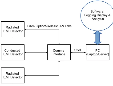
Figure 1. shows the concept of the low-cost IEMI detection system being developed in the STRUCTURES project. Multiple sensors are coupled to a (protected) computer system
for warning, logging and analysis. Optical fibre
communications provide robust communications, though
wireless or wired links may be desirable in some cases.
Conducted IEMI Detector
Radiated IEMI Detector
Radiated IEMI Detector
Comms interface
PC (Laptop/Server) Fibre Optic/Wireless/LAN links
USB
Software: Logging Display &
Analysis
Figure 1. Low cost IEMI detector system concept
The block diagram for individual low-cost detectors is shown in Figure 2. In a low cost system it is desirable that each detector unit operate on battery power for extended periods. Low-power consumption could be achieved with the assistance or solar or other scavenged energy sources.
Low power operation is possible for many microcontrollers, and wireless links such as Zigbee [8]. Optical links can also be operated at very low power consumption levels, making battery operation possible. Wired network connections tend to have much higher power consumption requirements but power over Ethernet is becoming readily available.
Whilst commercial broadband logarithmic detectors with high dynamic range and operating frequencies up to 10 GHz are available, their power consumption is high, around 100 mA, and so they are not suitable for battery powered operation. We have fabricated a low power log detector (Figure 3. ) which has a dynamic range of greater than 40 dB (Figure 4. ) and consumes about 2 mA. Currently, the upper limit of the dynamic range is limited by the detector breakdown voltage (4 V) and may be improved by use of a diode with a higher breakdown voltage.
Microcontroller
Fibre-optic
Wireless (IEEE 802.15.4)
LAN (Ethernet)
USB Radiated IEMI
Sensor
Conducted IEMI Sensor
Battery
AC Charger Solar Charger
To control/logging
[image:3.595.319.559.52.235.2] [image:3.595.321.555.508.652.2]V1
5
SINE(0 1 100meg 10n 0 0 400) AC 1 0
V3 C1 10p V4 5 LTC6246 U3 R2 500 D1 BAT17 D2 BAT17 R3 5100 R4 50k R5 100k C2 100p C3 100p C4 566f C5 245f R6 340.84L1 4.43n R7 100 LTC6246 U1 R8 500 C6 10p R9 500Meg V2 0 R10 50k R1 100k R11 2Meg R12 2.5Meg V5 4.29 D3 1N4148 D4 1N4148 D5 1N4148 R13 250k R14 250k V + V + N S H D N N S H D N O U T IN V + O U T 2 NSHDN V -V -V -D E T 1 D E T 2 A N T D E T IN V + V O S .tran 10u
;ac dec 50 1Meg 1000Meg
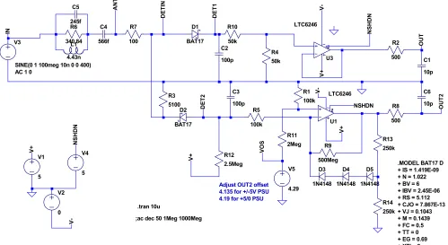
.MODEL BAT17 D + IS = 1.419E-09 + N = 1.022 + BV = 6 + IBV = 2.45E-06 + RS = 5.112 + CJO = 7.867E-13 + VJ = 0.1043 + M = 0.1439 + FC = 0.5 + TT = 0 + EG = 0.69 + XTI = 2
Adjust OUT2 offset 4.135 for +/-5V PSU 4.19 for +5/0 PSU
Figure 3. A low power, low cost detector
Figure 3. shows the radiated IEMI detector circuit driven by a source which represents a simple dipole model [9] (L1, R6, C4, C5). The shunt resistance R3, along with the antenna capacitance C4 define the low cut-off frequency. In this prototype, a positive peak detector (D1, C2, R10, & R4) with linear response was included with a buffer amplifier in order to allow observation of the detector output directly. A negative peak detector (D2, C3, & R5) feeds an inverting logarithmic amplifier which is to be used to drive a comparator and Analogue to Digital Converter (ADC) on the microcontroller. R12 provides a small bias to the diodes and ensures that the inverting op-amp has a small (~25 mV) positive output so that it functions adequately with a single supply rail. Figure 4. Shows the measured dynamic range of the fabricated detector.
Figure 4. Dynamic range of the low-cost detector
The choice of detector RC time constant and operational amplifier determine both the time response and power consumption of the system. This should be matched to the sample rate of the ADC on the microcontroller which is of the order of 1 Msample/s. The LTC6264 amplifiers used here have
a gain bandwidth product of 180 MHz and a 90V/s slew rate
with a quiescent current of less than 1 mA. This means that the buffer for the positive detector has a rise time of less than 20 ns. The rise time of the logarithmic amplifier depends on the
signal amplitude and is significantly slower, around 2s. The
performance is adequate to allow envelope capture of some pulsed waveforms. The decay time of the detector must also be slow enough for the ADC to capture amplitude information for shorter pulses and is currently set so the decay in one microsecond is about 10%.
[image:4.595.54.553.61.334.2] [image:4.595.41.291.542.686.2] [image:4.595.312.552.554.677.2]Figure 6. Simulated time response of low-power, low-cost detector for sine wave input with detector capacitors set to 10 pF
The time response of a simple detector presents a challenge. The detector capacitance must be charged through the antenna capacitance. Also for smaller signals the diode conducts less and the rise time becomes longer. The prototype constructed uses a 100 pF capacitance which results in a detector rise-time of about 2s. This is compatible with the logarithmic amplifier performance as can be seen in Figure 5. The detector response can be improved by reduction in the detector capacitance as shown in Figure 6. However the logarithmic amplifier rise-time is limited for small signals as it is operating with a high gain. The buffer amplifier on the positive detector is able to follow the faster rise time and can be used to operate a comparator for short-pulse detection.
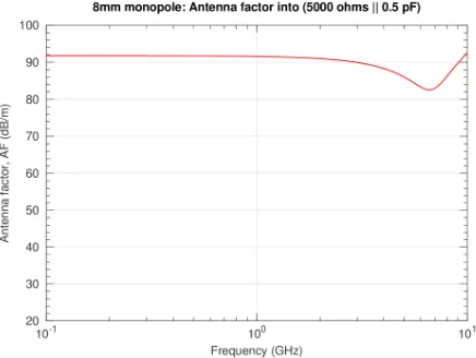
Kanda [9] showed that it is possible to achieve a flat frequency response over a broad bandwidth using a simple dipole antenna directly connected to a detector diode. This is due to the fact that the detector charges its output capacitor which eventually reverse-biases the diode so the antenna sees only the diode capacitance as its load. A dipole like antenna below resonance exhibits a purely capacitive impedance and this acts as a frequency independent potential divider with the diode capacitance. An 8 mm monopole has a quarter wave resonant frequency of approximately 9 GHz and Figure 7. shows the simulated frequency response of the monopole driving the capacitive load of the diode. A significant dip in antenna factor can be seen as the antenna passes through resonance.
Figure 7. Antenna factor of 8mm monopole driving detector load
Considering Figure 4. , if we assume that -40dBm in a 50
system is the limit of useable sensitivity for the detector, then this corresponds to a voltage of V=4.47 mV. For an 8mm dipole with a 92 dB/m antenna factor, the corresponding minimum detectable field sensitivity is:
E
1
V
AF
1
178
V/m
Since the antenna forms a capacitive potential divider with the detector, the antenna factor can be controlled by modifying the antenna capacitance. Figure 8. shows an 8 mm high antenna with increased capacitance. We chose the shape as recent experience in designing a broadband antenna for reverberation chambers [11] shows that the taper at the base radiates well at frequencies above resonance and it suppresses the effect of the monopole resonance(s). It can be seen (Figure 9. ) that the increase in capacitance results in a substantial reduction of antenna factor. The reduced antenna factor of 55 dB results in an increased sensitivity of the detector such that the minimum detectable field is:
E
2
V
AF
2
2
.
5
V/m
Thus the sensitivity of the detector can be adjusted by choice of a suitable antenna capacitance.
Figure 8. An antenna with increased capacitance
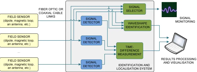
[image:5.595.47.280.55.179.2] [image:5.595.329.556.339.463.2] [image:5.595.323.563.513.680.2] [image:5.595.59.277.532.696.2]Figure 10. Block diagram of the IEMI identification and location system
B. Towards identification and location system
The described low cost detector system is able to determine basic waveform features, such as whether a threat is a continuous wave, long or short single pulse. However, it is not
capable of distinguishing between and extracting the
parameters of typical IEMI signal shapes, such as trains of sine wave pulses, damped sine pulses, and double-exponential pulses since IEMI signals are typically very short and exhibit very fast rise times. Proper identification of such signals can be accomplished in at least two ways: (i) by recording the waveform of the signal and analyzing its shape in the time or frequency domain offline, or (ii) by measuring and analyzing (algorithmically) the durations of the positive and negative half-pulses of the signal.
An identification and location system is also being developed as part of the STRUCTURES programme. Figure 10. shows a simplified block diagram of a more complex, and thus likely more expensive, system which can perform the detection of the attack, the localization of a radiated IEMI source, and the identification of the waveform of the malicious signal. The inputs to the system are signals collected from a set of spatially distributed field sensors. The main building blocks are signal detectors, needed to spot the attack, and the core signal-processing modules: waveshape identification and time-difference measurement modules. The signal selector block redirects one of the input signals to the output for visual analysis. The identification module measures and analyzes the duration of received signal half-pulses, to determine the approximate waveshape of the IEMI signal. The time-difference module detects the initial rising edge of the signals from the different sensors and measures the time delay between them. This module is crucial for calculating the location of the source using the Time Difference of Arrival Algorithm (TDoA). This algorithm is selected based on an analysis of the existing localization algorithms and the simulation results presented in [12].
IV. CONCLUSIONS
We have described the low cost, low power IEMI detector system, and given a brief overview of an identification and location system, being developed as part of the STUCTURES
Programme. This paper has focused on the design of the radiated IEMI detector for the low cost system. The conducted interference detector is yet to be developed.
REFERENCES
[1] Radasky, W.; Baum, C. & Wik, M. , "Introduction to the special issue on high-power electromagnetics (HPEM) and intentional electromagnetic interference (IEMI)" , Electromagnetic Compatibility, IEEE
Transactions on,vol. 46, no. 3, 314 - 321 , Aug. 2004.
[2] Adami, C.; Braun, C.; Clemens, P.; Suhrke, M.; Schmidt, H. U. & Taenzer, A. , "HPM detection system for mobile and stationary use" ,
EMC Europe 2011 York, 1-6 2011.
[3] Hoad, R. & Leaver, A. , "The Application Intentional Electromagnetic Interference (IEMI) Detectors for Safety and Security" ,EMC Europe
Workshop 2007, Paris, France, 14th - 15th June2007.
[4] Adami, C.; Braun, C.; Clemens, P.; Joester, M.; Suhrke, M.; Schmidt, H. & Taenzer, H. , "HPM Detector System With Frequency Identification" ,
Proceedings of the 8th Future Security Research Conference 2013
(Berlin)2013.
[5] Zammit, C. & Kerr, B. , "General Electronic Equipment Microwave Susceptibility Trend as a Function of frequency" ,Proc. Institution of
Engineering and Technology Pulsed Power Symposium, 59-61 2006.
[6] Hoad, R.; Carter, N.; Herke, D. & Watkins, S. , "Trends in EM susceptibility of IT equipment" ,Electromagnetic Compatibility, IEEE
Transactions on,vol. 46, no. 3, 390 - 395 , aug. 2004.
[7] Giri, D. & Tesche, F. , "Classification of intentional electromagnetic environments (IEME)" , Electromagnetic Compatibility, IEEE
Transactions on,vol. 46, no. 3, 322 - 328 , aug. 2004.
[8] ZigBee Alliance, "ZigBee Specification" , January 2008. , Available from: http://www.zigbee.org/en/index.asp
[9] Tang, T. G.; Tieng, Q. M. & Gunn, M. W. , "Equivalent circuit of a dipole antenna using frequency independant lumped elements" ,IEEE
Transactions on Antennas and Propagation,vol. 41, no. 1, 100-103 ,
January 1993.
[10] Kanda, M. & Driver, L. , "An Isotropic Electric-Field Probe with Tapered Resistive Dipoles for Broad-Band Use, 100 kHz to 18 GHz" ,
Microwave Theory and Techniques, IEEE Transactions on,vol. 35, no.
2, 124-130 , February 1987.
[11] Marvin, A.; Esposito, G.; Dawson, J.; Flintoft, I.; Dawson, L.; Everard, J. & Melia, G. , "A wide-band hybrid antenna for use in reverberation chambers" , Electromagnetic Compatibility (EMC), 2013 IEEE
International Symposium on, 222-226 , August 2013.
[12] Stojilovic, M.; Menssen, B.; Flintoft, I.; Garbe, H.; Dawson, J. & Rubinstein, M. , "TDoA-Based Localisation of Radiated IEMI Sources",
EMC Europe2014.