© 2017, IRJET | Impact Factor value: 5.181 | ISO 9001:2008 Certified Journal | Page 1382
Study of Multipurpose Road Cleaning Machine
Aman khan
1, Anurag Pannase
2, Amol Sharnagat
3, Prof. Gaurav Gohane
41Aman Khan, Student, JD College of Engineering and Management, RTMNU Nagpur 2Anurag Pannase, Student, JD College of Engineering and Management, RTMNU Nagpur
3Amol Sharnagat, Student, JD College of Engineering and Management, RTMNU Nagpur
4 AsstProf. Gaurav Gohane , Dept. of Mechanical Engineering, JD College of Engineering and Management, RTMNU
Nagpur, India
---***---Abstract –
The multipurpose road cleaning machine hasa wide range of applications. It can be used on all kind of roads in rural as well as the urban. Working on the basic principle of science, the project is a collaboration of mechanical, electrical and electronic devices. To overcome the rising issues of cleanliness in India the multipurpose road cleaner can play a vital role. The cleaner solves the problem of dusty roads, choked pipelines and manholes, removal of metal particles from road and also obstacles.The machine is an assembly of various rigid components, a chassis, some motors, micro controllers and various electro-mechanical devices whose working takes place on the various laws of physics and simple science.In this paper, our motive is to present a detailed qualitative study of cleaning system using the cleaner, the main focus being cleanliness with minimum utilization of resources available with us.
Key Words: road cleaner, multipurpose, motors,
components, arm
1. INTRODUCTION
This document is template. Good sanitization and cleaning leads to proper health of human beings. It directly effects the environment and the surrounding.[1] In recent years cleanliness is
becoming an important factor for the betterment of the nation and so, to support the cause we have conducted a study, prepared a design and working of an Automatic Multipurpose Road Cleaner. The cleaner is an approach to deliver easy and time efficient cleaning of roads, by reducing human efforts. There are innumerous functions of the remote operated cleaner mainly[5].1) Cleaning of
roads by brushes or broom like structures. 2) Removes the dust from roads with the help of blowers. 3) A function by which pipes and manholes can be cleaned. 4) A picker (arm like structure) use to pick and place various objects.
In development of the field cleanliness one
can find a number of research papers and studies, but this paper deals with study of various components which function in different ways in order to clean the environment and provide an eco-friendly, clean surrounding.[6] This cleanliness can be
achieved by utilizing all the functions of the road cleaner to the optimum level. The basic idea is to generate a machine which works on basic principles of physics, using mechanical, electrical and electronic components and devices. Making an assembly of the components and ultimately creating a machine which can be the answer to various cleaning issues in a single unit.[7] the manually operated units are very
laborious and time consuming and as every coin has two sides the fuel operated machines are very costly. So we have thought of an alternative which can be used for nullification of the former limitations.[8]
2. PROBLEM STATEMENT
© 2017, IRJET | Impact Factor value: 5.181 | ISO 9001:2008 Certified Journal | Page 1383 waste to the sides of the road. This waste can then be
cleaned by the sweepers and ultimate cleanliness can be achieved. Apart from this the choked manholes and sewer pipes can be cleaned by the multipurpose road cleaning machine.
3. LITERATURE REVIEW
3.1 M Ranjit Kumar and N Kapilan[1]
The conventional floor cleaning machines is most widely used in airport platforms, railway platforms, hospitals, bus stands, and malls and in many other commercial places. These devices need an electrical energy for its operation and not user friendly. In India, especially in summer, there is power crisis and most of the floor cleaning machine is not used effectively due to this problem, particularly in bus stands. In this work, modeling and analysis of the floor cleaning machine was done using suitable commercially available software. From the finite element analysis, we observe that the stress level in the manually operated floor cleaning machine is within the safe limit.
3.2 Prathmesh Joshi, Akshay Malviya & Priya Soni[2]
This project report is based on the “Manually Driven Platform Cleaning Machine” which serves the basic needs of cleaning large floors.
3.3 Ritvick Ghosh, H R Vinay Kumar, Dattatraya, Pavan Kumar B. Hiremath, Prof. Pradeep Kumar[3]
This paper elaborates the design and fabrication of a floor cleaner which runs purely on mechanical power and also has the capability of being ridden at low speeds by the user. The mechanism used to drive the cleaning mechanism would be similar to the one used in a spinning mop commonly known as a ‘magic mop’. The mechanism works using a bevel gear system wherein high speed multiplications can be obtained using the right gear specifications. The input to the system would be in the form a foot-pedal accessible to the user.
3.4 Sandeep J. Meshram & Dr G.D.Mehta[4]
This paper presents the design and fabrication of Tricycle operated street cleaning machine with the related search. At present we have few automated machines which are foreign made and can be used in our country. This basically instigates to thing for an alternative mechanism called Street cleaning process.
3.5 Manreet Kaur & Preeti Abrol[5]
Manual work is taken over the robot technology and many of the related robot appliances are being used extensively also. Here represents the technology that proposed the working of robot for Floor cleaning. This floor cleaner robot can work in any of two modes i.e. “Automatic and Manual”.
4. DESIGN METHODOLOGY
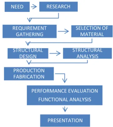
[image:2.595.328.509.425.628.2]The procedure mentioned in the flow chart was followed during design and fabrication of the product.
Fig -1: Flow chart of design and fabrication methodology
1. Market Analysis to identify problems and requirements
2. Selection of suitable fabrication materials. 3. Concept design of structure
4. Analysis of design and optimization 5. Start of production and fabrication
6. Testing and evaluation of overall performance
NEED RESEARCH
REQUIREMENT GATHERING
SELECTION OF MATERIAL
STRUCTURAL DESIGN
STRUCTURAL ANALYSIS
PRODUCTION FABRICATION
PERFORMANCE EVALUATION FUNCTIONAL ANALYSIS
© 2017, IRJET | Impact Factor value: 5.181 | ISO 9001:2008 Certified Journal | Page 1384 7. Incorporating necessary modifications
8. Presentation and report formation.
4. CONSTRUCTION
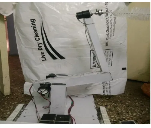
The figure shows the actual three dimensional structure of the cleaner. The cleaner mainly consists of 5 units. The chain drive, pipe cleaner unit, mechanical arm unit, brushes and blower. The whole assembly is mounted on a frame made up of wood and aluminum bars as wood is a poor conductor of electricity and aluminum is light in weight. Towards the fore part of the body which we call the chassis is the brush unit. The brush unit is mounted using L-clamps on which motor is mounted and the brushes are attached. Above the brush unit is mounted the mechanical arm unit using aluminum bars, motor, clamps and the worm and gear mechanism operated 2 jaw mechanical arm. On middle section of the machine is mounted the pipe cleaner section. Two bars are clamped vertically on which the motors are clamped of the top section of the bars. To the bars is attached the L section with the help of shafts of the motor. The brush is attached via a motor which rotates to clean the pipes. Just beside the pipe cleaner unit is batteries post to which are the connectors attached with wires to the remote. On the rear side is a high speed blower; this blower rotates at high speed to blow out the dust dirt and wastes towards the sides of the roads. Lastly the chains drive mechanism on which the whole machine will move. The mechanism is fitted with the help of metal clamps and moves with the help of motors. By the use of this the vehicle moves front back as well as takes turn. This is a brief description of the machine’s construction.
Fig- 2: 3D diagram of road cleaner
5. WORKING
5.1 CHAIN DRIVE UNIT
The chain drive unit consists of 36 chain links. These are mounted on wheels of diameter of 8 centimeters. The wheels are attached to the shaft connected to the DC motor. The motor is a basic spur geared motor which runs at about 38 rotations per minute. As the switch is pushed on the power is supplied to the motor and motor starts rotating. Along with the motor rotates the chain drive. The drive can rotate in three ways, one to move forward, one to the reverse and lastly in opposite directions to take a turn.
Fig- 3: Actual chain drive used in machine
5.2 MECHANICAL ARM
© 2017, IRJET | Impact Factor value: 5.181 | ISO 9001:2008 Certified Journal | Page 1385 Fig -: Mechanical Arm
5.3 PIPE CLEANER
The pipe cleaner unit basically consists of 3 motors out of which two running at 36 RPM while the third motor rotates with 1200 RPM. Function of the faster motor is to rotate in clockwise as well as anti-clockwise direction to clean the pipes, hoses and sewer lines while the two motors are used to position the brush and the pipe cleaning unit. The design of the arm holding the brush is L shaped so that it can clean on both sides of the roads.
Fig –: pipe cleaner unit
5.4 BRUSHES AND BLOWERS
The brushes are situated on the front side of the vehicle. Purpose of the brushes is to extract the dirt and waste from the road and broom it aside cleaning the road. For this purpose we have used metal brushes which can remove dust and dirt from the road. Metal brushes have a long life and can also easily clean out wastes. This is done with the help of motors. On the rear side of machine is the high speed
[image:4.595.307.560.562.676.2]blower. Function of this blower is to blow out the unwanted particles from the road towards the sides of the roads so that they can be cleaned up easily. This is done by providing an inclination to the fan which operates at very high speed to blow away the unwanted wastes from the road.
Fig -: Blower and Brushes
5.5 CONTROLER AND ELECTRICAL UNIT
This unit constitutes of the heart of the system. Without the electrical system none of the units in the machine can work. To operate the road cleaner we require a power of about 12volts. To fulfill this requirement we have used two 6volts batteries. These batteries are connected together such that they come up to the power requirement. Wires connect the batteries to the connectors. While on one side of the connectors is the wires going to the machine, on the other side are the wires going to the controller. Controller consists of 8 DPDT switches. These switches are double pole double throw switches connected in parallel to function each operation accordingly. As the switch is pressed towards a side the specific function associated with the switch will work. A skilled operator can operate more than half of the functions at the same time.
© 2017, IRJET | Impact Factor value: 5.181 | ISO 9001:2008 Certified Journal | Page 1386 6. CONCLUSIONS
The main motive of the project is to cover the aspects of cleanliness in the society. It focuses on cleanliness of roads, paths and other floors. The multiple applications provide a wide range of functions in which we can clean a pipe, remove metal particles harmful for the road, remove dust and dirt from the road, provide a pick and place mechanism by which obstacles can be removed. By application of simple engineering technology we learned in our engineering life we have assembled such a vehicle which has multiple features being cost effective at the same time. The low budget project is very useful for the society and being cost effective and energy efficient can play a vital role in cleanliness of India.
ACKNOWLEDGEMENT
We would like to take this opportunity to express deep regard and profound gratitude to Prof. Gaurav Gohane for his guidance, constant encouragement and valuable feedback throughout the work. The perceptive criticism kept us working to accomplish the project in a better way. Working under his guidance was an extremely knowledgeable experience for us. We would also give a sincere gratitude to our teachers, colleagues and friends who have helped us with the project.
REFERENCES
[1] M. Ranjit Kumar and N. Kapilan, “Design and Analysis
of manually operated floor cleaning machine,” IJERT ISSN: 2278-0181 Vol. 4 Issue 04, April-2015.
[2] Prathmesh Joshi, Akshay Malviya and Priya Soni,
“Manual Driven Platform Cleaner,” IJETAE ISSN 2250-2459, ISO 9001:2008 Certified Journal,Volume 3, Issue 8, August 2013
[3] Ritvick Ghosh, H R Vinay Kumar, Dattatraya, Pavan
Kumar B. Hiremath, Prof. Pradeep Kumar K.V. “Design and Fabrication of A Pedal-Operated Floor Mopping Machine,” IJETAE ISSN 2250-2459, ISO 9001:2008 Certified Journal, Volume 6, Issue 5, May 2016
[4] Sandeep J. Meshram and Dr. G.D.Mehta “Design And
Development Of Tricycle Operated Street Cleaning Machine,” ISSN 0975 – 668X| Nov 15 To Oct 16 | Volume-04, Issue-01
[5] Manreet Kaur and Preeti Abrol, “Design and
Development of Floor Cleaner Robot (Automatic and Manual),” International Journal of Computer Applications (0975 – 8887) Volume 97– No.19, July 2014
[6] Liu, Kuotsan and Wang, Chulun, “A Technical Analysis