This is a repository copy of
An entangled-LED driven quantum relay over 1 km
.
White Rose Research Online URL for this paper:
http://eprints.whiterose.ac.uk/94061/
Article:
Varnava, C., Stevenson, R.M., Nilsson, J. et al. (7 more authors) (2015) An entangled-LED
driven quantum relay over 1 km. (Unpublished)
[email protected] https://eprints.whiterose.ac.uk/ Reuse
Unless indicated otherwise, fulltext items are protected by copyright with all rights reserved. The copyright exception in section 29 of the Copyright, Designs and Patents Act 1988 allows the making of a single copy solely for the purpose of non-commercial research or private study within the limits of fair dealing. The publisher or other rights-holder may allow further reproduction and re-use of this version - refer to the White Rose Research Online record for this item. Where records identify the publisher as the copyright holder, users can verify any specific terms of use on the publisher’s website.
Takedown
If you consider content in White Rose Research Online to be in breach of UK law, please notify us by
C. Varnava,1, 2 R. M. Stevenson,1,∗ J. Nilsson,1 J. Skiba-Szymanska,1 B. Dzurňák,1,† M. Lucamarini,1 R. V. Penty,2 I. Farrer,3 D. A. Ritchie,3 and A. J. Shields1
1
Toshiba Research Europe Limited, 208 Science Park, Milton Road, Cambridge CB4 0GZ, UK
2
Cambridge University Engineering Department, 9 J J Thomson Avenue, Cambridge CB3 0FA, UK
3
Cavendish Laboratory, University of Cambridge, J J Thomson Avenue, Cambridge CB3 0HE, UK
Quantum cryptography allows confidential information to be communicated between two parties, with secrecy guaranteed by the laws of nature alone. However, upholding guaranteed secrecy over quantum communication networks poses a further challenge, as classical receive-and-resend routing nodes can only be used conditional of trust by the communicating parties. Here, we demonstrate the operation of a quantum relay over 1 km of optical fiber, which teleports a sequence of photonic quantum bits to a receiver by utilizing entangled photons emitted by a semiconductor LED. The average relay fidelity of the link is 0.90±0.03, exceeding the classical bound of 0.75 for the set of states used, and sufficiently high to allow error correction. The fundamentally low multi-photon emission statistics and the integration potential of the source present an appealing platform for future quantum networks.
The critical importance of information security in the digital age has led to the pervasive use of cryptography. The emerging field of quantum cryptography[1, 2], offers a means to guarantee the security of digital interactions which can be proven information theoretic secure. Re-ported quantum key distribution systems are typically based on weak-coherent optical pulses, and have evolved rapidly. Such systems allow unique cryptographic keys to be shared between directly connected users on point-to-point[3–5] or point-to-multipoint links[6].
In contrast, the situation for networks connecting mul-tiple parties is less developed. One solution has been to demonstrate nodal networks, based on individual quan-tum links connected by classical intermediary systems[7]. The result of this type of network topology is that end users are required to trust the intermediary systems, which arguably diminishes the value of the underlying quantum cryptography.
To establish fully quantum multi-partite networks, it is necessary to route quantum signals through a backbone of quantum nodes. This can be achieved by leveraging quantum entanglement to set up non-local correlations between measurements by end users. Examples of such schemes are distribution of entangled photon pairs to end users, where local measurements are performed[8], or conversely, where photons are sent by two users to be projected into a Bell state by an intermediate quan-tum node[9–11]. Photonic quanquan-tum repeaters[12] and relays[13] employ both of these effects to teleport entan-gled or single qubits respectively in a manner that can be chained to create a fully quantum network for which theoretically proven quantum security can be preserved. Here, we report operation of a quantum relay over 1 km
∗Electronic address: [email protected]
†Current Address: Department of Physics and Astronomy, Univer-sity of Sheffield, Sheffield S3 7RH, UK
d) top contact
InAs QDs DBRs
a) bond ball b) (Au)
0 5 10 15 20 0
1
Intensity (a.u.
)
(ns)
884 886 888 0
X
Intensity (a.u.
)
(nm)
B
20 m
c)
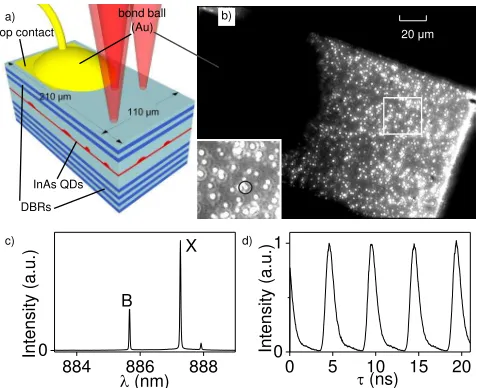
Figure 1: (a) Schematic of the ELED used in this experiment (not to scale). The entangled photon source is an InAs quan-tum dot (QD) embedded in a p-i-n diode structure with a cav-ity centred at ~886nm, between top and bottom distributed Bragg reflectors (DBRs). (b) Microscope image of the mesa used for this experiment. Individual quantum dots can be identified as points of light in the image. The dark circular area is the gold bond to the top contact. The quantum dot chosen for the experiment is identified in the inset. (c) Biexci-ton (B) and exciBiexci-ton (X) electroluminescence spectrum under experimental biasing conditions. (d) Time-resolved biexciton electroluminescence.
of optical fiber using entangled photons generated by a light emitting diode to teleport photonic qubits encoded on weak coherent pulses emitted by a laser. Compared to previously reported quantum relays[14] and photonic teleportation over significant distances[15, 16], our sys-tem is directly electrically driven using a simple semi-conductor device, offering a route to large-scale network deployments. Teleporting weak coherent states offers
[image:2.612.322.561.274.468.2]2
tential enhancements to state-of-the art quantum key dis-tribution systems, as it creates output photons with sub-Poissonian statistics immune to the photon number split-ting attack[17, 18], and protects against intrusions[19].
At the heart of our quantum relay is an entangled-light-emitting diode (ELED)[20], as shown in Fig. 1(a). It con-sists of a layer of self-assembled indium arsenide quantum dots within a gallium arsenide microcavity (Appendix). We have optimized the resistance and capacitance of the device to allow it to be driven by short electrical pulses, without compromising entanglement fidelity or photon coherence. This has allowed electrically triggered quan-tum teleportation using an LED, which has previously been limited to only d.c. operation[18, 21].
An image of the ELED in operation is shown in Fig. 1(b). Individual points of light are observed, correspond-ing to light emission from individual quantum dots. We select emission from a chosen quantum dot, indicated in the inset image, by collection with a single mode fibre. The emission spectrum measured by a grating spectrom-eter and CCD camera is shown in Fig. 1(c). Two strong emission lines are observed corresponding to the first, biexciton photon (B) and second, exciton photon (X) emission. The B and X emission lines are then spec-trally filtered with a diffraction grating to isolate them from each other and other emission from the device, in-cluding that originating from the quantum well-like wet-ting layer, and any other nearby quantum dots (such as the weak peak seen at ~888 nm).
The ELED was driven at a repetition rate of 203 MHz, with pulses of nominally 0.4V amplitude and 490 ps du-ration. Time-resolved electroluminescence was measured under these conditions and shown in Fig. 1(d) for B as a black line. The emission is strongly pulsed, and well contained within each cycle.
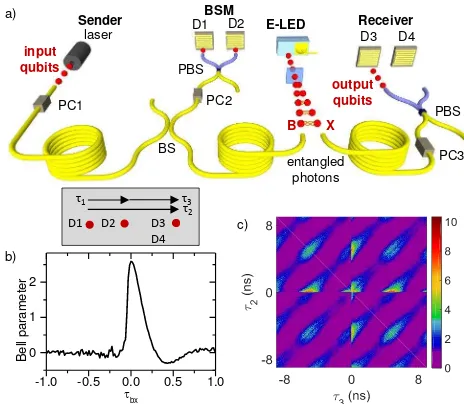
The experimental quantum relay system is shown in Fig. 2(a). It comprises 4 sections separated by three 350 m fiber optic links. The first, ‘Sender’ section is thus separated from the last ‘Receiver’ section by 1.05 km of optical fiber. Entangled photons emitted by the ELED are divided, the B photons are sent to the Bell-State Mea-surement (BSM) section, and theX photons are sent to the ‘Receiver’. The ‘Sender’ employs a wavelength tun-able c.w. laser diode, from which pulses are generated by an external optical intensity modulator, tuned to the frequency of the ELED. The polarized pulses are then rotated by a polarization controller PC1 to encode the qubit, before transmission to the ‘BSM’ section.
At the ‘BSM’ section, an imbalanced beamsplitter BS combines 95% of the B photons with 5% of the laser photons into one output arm, before a polarization con-troller PC2 and polarizing beamsplitter projects horizon-tal (H) and vertical (V) polarized photons onto super-conducting single photon detectors (SSPD) D1 and D2. The function of this section is to perform a Bell state measurement in the state (|HLVBi+|VLHBi)/
√
2 where subscriptsLandB denote photons originating from the laser and biexciton respectively. Such a measurement
col-PC1
PBS
laser E-LED
input qubits
Sender D1 BSM D2 Receiver
D3 D4
output qubits entangled photons BS PC2 PC3 PBS B X
1
D3
D4
D1 D2
2 3
-1.0 -0.5 0.0 0.5 1.0
0 1 2 bx Be ll pa rame ter b) c) a)
Figure 2: (a) Quantum relay experimental setup. The Sender encodes photons from an externally modulated laser diode with qubit states|Hi,|Vi,|Di,|Ai, using a polarization con-troller PC1, to be transferred to the Receiver by quantum teleportation. Sender and Receiver are separated by ~1 km of fiber and a Bell-State Measurement (BSM) node in be-tween. The BSM and Receiver share an entangled pair of photons emitted from the ELED. The input qubits interfere with biexciton photons on beamsplitter BS. Once detectors D1 and D2 measure their state, teleported output qubits are detected with a polarizing beamsplitter (PBS) at D3 and D4. All state calibrations at each node are done with polarization controllers (PC). (b) Bell parameter extracted from experi-mental data. (c) Average third-order correlationg(3). Pulsed character of the correlations is observed. The single-photon property of emission is seen as a dip in coincidences atτ2=τ3. Higher three-photon coincidences running alongτ2 = 0 and
τ3= 0 originate from elevated probability of the ELED emit-ting a pair of photons simultaneously.
lapses the formerly entangledX photon into a quantum state related to the input qubit together with a trivial unitary transformation[22]. In this work, input qubits of the form cos(a)|HLi+eibsin(a)|VLiare teleported to the
state cos(a)|VXi+eibsin(a)|HXi.
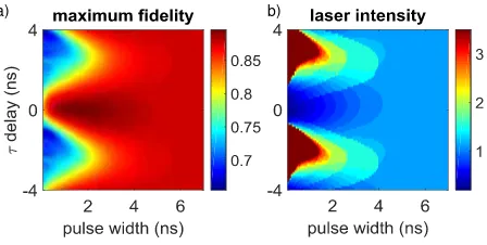
Theoretical analysis of the intricate time-dependent three-photon fields reveals a range of laser pulse condi-tions for which the calculated peak teleportation fideli-ties are close to optimum (Appendix). The laser pulse properties observed at detectors D1 and D2 were set ac-cordingly, with integrated intensity of 0.85 relative to the Bpulse, a fitted Gaussian FWHM of 0.95±0.01 ns, and a delay of the laser pulse after theB pulse of 0.60±0.02 ns relative to maximum overlap.
[image:3.612.322.554.52.254.2]respec-tively. From these measurements it is possible to deter-mine Bell’s parameter to indicate the degree of entangle-ment present[23, 24]. The result is shown in Fig. 2(b) as a function of the time delayτBX between a biexciton
photon detected at D1 or D2, and an exciton photon at D3 or D4. For simultaneously detected photons, a Bell parameter of 2.59±0.01 is observed, exceeding the limit of 2 for classical behavior, and corresponding to 91.8 % of the ideal value of 2√2. To our knowledge, this is the first time entanglement has been distributed by a quantum dot source over a distance longer than a few meters.
The quantum relay was operated using polarization en-coded BB84 quantum states[25], using the rectilinear and diagonal bases. Three-photon detection statistics were recorded between a pair of photons at D1 and D2, and one at D3 or D4. The polarizations of the input qubit and measurement basis, controlled by PC1 and PC3 respec-tively, were switched during the experiment so that a ran-domized sequence of teleported qubits could be recorded. Fig. 2(c) shows the measured third-order correlation functiong(3)averaged over all 4 polarization inputs, and
over the corresponding co- and cross- polarized outputs. The horizontal and vertical axes are the time delays τ2
and τ3 between photon detection at D1 or D2
respec-tively, and a photon at D3 or D4. The intensity dis-tribution has highly pulsed character, with peaks occur-ring when the delays τ2 and τ3 are an integer multiple
of the ~ 4.9 ns repetition period. This is in contrast to previous reports of quantum teleportation with quantum dots, which operated in continuous mode. Stronger in-tensity peaks are observed forτ2= 0 andτ3= 0, as
exci-ton emission directly following biexciexci-ton emission is en-hanced. For coincident detection at D1 and D2,τ2=τ3,
a low intensity line indicates a suppression in detecting twoBphotons simultaneously due to the sub-Poissonian nature of the ELED source.
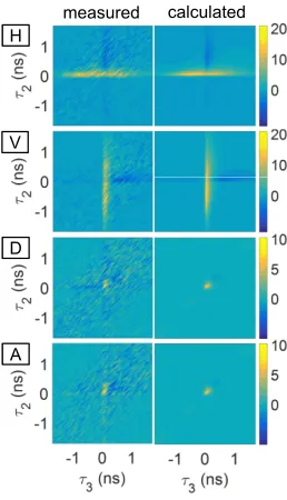
The polarization dependence of the quantum relay is evaluated from the difference between third-order corre-lation measurements with the expected, and unexpected (i.e. orthogonal to expected) output polarizations. Such g(3) contrast measurements are presented in Fig. 3 as a
function ofτ2 and τ3 for each of the input qubit states
H,V,D, and A. High contrast at τ2 = 0 (τ3 = 0) is
ob-served due to H (V) input laser photons exciting the D1 (D2) detector, so that contrast is dominated by correla-tion between X and a B photon at D2 (D1). The cor-relation contrast for D and A however looks quite dif-ferent, dominated by a peak centered atτ3=τ2= 0, as
two-photon interference between simultaneously detected photons is required for teleporting states in a superpo-sition state. Calculations, shown in the right column, agree well with observations (Appendix).
The performance of the quantum relay is assessed by determining the relay fidelity FP, which for each input
photon stateP is determined by:
FP(τ3, τ2) =gP(3)′(τ3, τ2)/(gP(3)′(τ3, τ2) +gQ(3)′(τ3, τ2)),
V
D
A
measured H
calculated
Figure 3: Difference between expected and unexpected third-order correlationsg(3)as a function of photon detection time delaysτ2 andτ3. Measured and calculated results are shown in the left and right column respectively, corresponding to input states H, V, D, and A (from top to bottom).
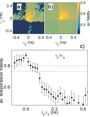
where P′ and Q′ are the expected and orthogonal un-expected output polarizations respectively. Averaging across the four input states H,V,D, and A gives the aver-age relay fidelityF, which is plotted in Fig. 4(a). A clear peak is observed aroundτ2 =τ3 = 0, where the fidelity
clearly exceeds 0.75, the limit for optimal classical tele-portation schemes using four-state protocols. Calculated behavior, shown in Fig. 4(b), shows similar features. The maximum measured value ofF is more clearly ob-served in Fig. 4(c), which plots F as a function of τ2
or τ3 for simultaneous detection of two photons at the
‘BSM’ section. The peak rises to a maximum value of 0.900±0.028, exceeding the six-state average fidelity re-ported previously[18]. The corresponding measured indi-vidual relay fidelities are 0.957±0.042 and 0.951±0.0475 from polar states H and V, and 0.845±0.064, 0.847±0.063 for superposition states D and A.
The high measured teleportation fidelities confirm that Sender and Receiver have shared information in excess of any information held by an eavesdropper. The difference between unity and the measured fidelity is the quantum bit error rate (QBER) of the shared key. Error correction protocols are known that can correct for QBER up to 0.2 in 4-state protocols[26], which corresponds to a minimum relay fidelity of 0.8, well below the experimentally mea-sured value.
[image:4.612.375.504.50.275.2]4
0.0 0.2 0.4
0.6 0.8
2=3
2,3 (ns)
a
v
.
te
le
p
o
rt
a
ti
o
n
f
id
e
lit
y
b)
c) a)
Figure 4: (a,b) Relay fidelity averaged across four input qubit states H, V, D, and A, as a function of the time delaysτ2and
τ3. (a) and (b) shown experimental and simulated results respectively. Note the measured fidelity is not defined some regions of the plot as no photons were detected due to the ELED or laser being ‘off’ (dark blue). (c) Average relay fi-delity as a function of time delayτ2 andτ3 forτ2=τ3. High fidelity points are concentrated around τ2,τ3=0, where the measured fidelity exceeds the classical limit of 0.75 shown by black dashed line. The threshold for 4-state error correction of 0.8 is shown as dashed red line.
photon is[29]:
R= 1−h(QZ)−h(QX),
where h is the binary entropy function. By replacing the QBERs QZ andQX in theZ andX basis by those
measured of 4.6% and 15.4% in the {H,V} and {D,A} bases respectively, we find that 0.111 secure key bits can be distilled from our Relay per detected photon.
A key advantage of quantum-dot based entangled light sources over spontaneous parametric down conversion
is that they can in principle operate ‘on-demand’ and deterministically deliver a single entangled photon pair when triggered, without detrimental additional pairs. In our experiments, we measure the second-order correla-tion for coincident X photons to be close to optimal at 0.046±0.008, highly suppressed from the Poissonian value of 1. Achieving maximal efficiency is predominantly limited by the photon collection efficiency, and the tem-poral post-selection window that heralds the occurrence of a teleportation event. Very high photon collection ef-ficiencies have been reported in optically driven quan-tum dot nanostructures[30, 31], for which electrical in-jection schemes could be developed. Increasing the tem-poral region of high fidelity may be achieved by matching the laser and biexciton pulse shapes, reducing the exci-tation pulse width, reducing the fine-structure-splitting of 4.2±0.1 µeV, and extending the coherence time of the biexciton photons, which at 141.6±4.2 ps limits the fi-delity of teleporting D and A states.
In conclusion, we have reported the operation of a 203 MHz clocked quantum relay over 1 km of optical fiber using an electrically driven semiconductor light source. The measured relay fidelity of laser generated photonic qubits of 0.900±0.027 exceeds both the thresh-old for quantum behavior, and the one for generating error corrected quantum keys with the BB84 protocol. Coupled with advances of quantum dot based entangled light sources at telecom wavelengths, our results suggest ELED technology could meet the need for a practical solution to create the backbone of future quantum net-works.
Acknowledgments
The authors would like to thank M. Razavi for theo-retical support and C. Panayi for useful discussions. The authors would like to acknowledge partial financial sup-port through the UK EPSRC and the EU Marie Curie Initial Training Network Spin-optronics.
[1] N. Gisin, G. Ribordy, W. Tittel, and H. Zbinden, Review of Modern Physics74, 145 (2002).
[2] V. Scarani, H. Bechmann-Pasquinucci, N. J. Cerf, M. Dusek, N. Lutkenhaus, and M. Peev, Rev. Mod. Phys.
81, 1301 (2009).
[3] D. Rosenberg, J. W. Harrington, P. R. Rice, P. A. Hiskett, C. G. Peterson, R. J. Hughes, A. E. Lita, S. W. Nam, and J. E. Nordholt, Phys. Rev. Lett. 98, 010503 (2007).
[4] A. R. Dixon, Z. L. Yuan, J. F. Dynes, A. W. Sharpe, and A. J. Shields, Appl. Phys. Lett. 96, 161102 (2010). [5] S. Wang, W. Chen, J.-f. Guo, Z.-q. Yin, H.-w. Li,
Z. Zhou, G.-c. Guo, and Z.-f. Han, Optics Letters 37, 1008 (2012).
[6] B. Fröhlich, J. F. Dynes, M. Lucamarini, A. W. Sharpe,
Z. Yuan, and A. J. Shields, Nature501, 69 (2013). [7] M. Peev, C. Pacher, R. Alléaume, C. Barreiro, J. Bouda,
Boxleitner, W. T. Debuisschert, E Diamanti, M. Dianati, J. F. Dynes, et al., New Journal of Physics11, 075001 (2009).
[8] A. K. Ekert, Phys. Rev. Lett.67, 661 (1991).
[9] S. L. Braunstein and S. Pirandola, Phys. Rev. Lett.108, 130502 (2012).
[10] H.-K. Lo, M. Curty, and B. Qi, Phys. Rev. Lett.108, 130503 (2012).
[11] Y.-L. Tang, H.-L. Yin, S.-J. Chen, Y. Liu, W.-J. Zhang, X. Jiang, L. Zhang, J. Wang, L.-X. You, J.-Y. Guan, et al., Phys. Rev. Lett.113, 190501 (2014).
[image:5.612.100.254.51.251.2][13] B. C. Jacobs, T. B. Pittman, and J. D. Franson, Physical Review A66, 052307 (2002).
[14] H. de Riedmatten, I. Marcikic, W. Tittel, H. Zbinden, D. Collins, and N. Gisin, Phys. Rev. Lett. 92, 047904 (2004).
[15] X.-S. Ma, T. Herbst, T. Scheidl, D. Wang, S. Kropatschek, W. Naylor, B. Wittmann, A. Mech, J. Kofler, E. Anisimova, et al., Nature489, 269 (2012). [16] F. Bussières, C. Clausen, A. Tiranov, B. Korzh, V. B.
Verma, S. W. Nam, F. Marsili, A. Ferrier, P. Goldner, H. Herrmann, et al., Nature Photonics 8, 775 (2014). [17] G. Brassard, N. Lütkenhaus, T. Mor, and B. C. Sanders,
Phys. Rev. Lett.85, 1330 (2000).
[18] R. M. Stevenson, J. Nilsson, A. J. Bennett, I. Farrer, D. A. Ritchie, and A. J. Shields, Nature Communications
4, 2859 (2013).
[19] H.-K. Lo and H. F. Chau, Science283, 2050 (1999). [20] C. L. Salter, R. M. Stevenson, I. Farrer, C. A. Nicoll,
D. A. Ritchie, and A. J. Shields, Nature465, 594 (2010). [21] J. Nilsson, R. M. Stevenson, K. H. A. Chan, J. Skiba-Szymanska, M. Lucamarini, M. B. Ward, A. J. Bennett, C. L. Salter, I. Farrer, D. A. Ritchie, et al., Nature Pho-tonics7, 311 (2013).
[22] C. H. Bennett, G. Brassard, C. Crépeau, R. Jozsa, A. Peres, and W. K. Wootters, Phys. Rev. Lett.70, 1895 (1993).
[23] J. F. Clauser, M. A. Horne, A. Shimony, and R. A. Holt, Phys. Rev. Lett.23, 880 (1969).
[24] R. J. Young, R. M. Stevenson, A. J. Hudson, C. A. Nicoll, D. A. Ritchie, and A. J. Shields, Phys. Rev. Lett. 102, 30406 (2009).
[25] C. H. Bennett and G. Brassard, Proceedings of the IEEE International Conference on Computers, Systems and Signal Processing, Bangalore, India, IEEE, New York pp. 175–179 (1984).
[26] H. F. Chau, Phys. Rev. A66, 060302(R) (2002). [27] G. Brassard and L. Salvail, inAdvances in Cryptology
-EUROCRYPT ’93, Lecture Notes in Computer Science 765, edited by T. Helleseth (Springer-Verlag Berlin Hei-delberg, 1994), pp. 410–423.
[28] H.-K. Lo, H. F. Chau, and M. Ardehali, J. Cryptology
18, 133 (2005).
[29] M. Koashi, New Journal of Physics11, 045018 (2009). [30] A. Dousse, J. Suffczynski, A. Beveratos, O. Krebs,
A. Lemaître, I. Sagnes, J. Bloch, P. Voisin, and P. Senel-lart, Nature466, 217 (2010).
[31] J. Claudon, J. Bleuse, N. S. Malik, M. Bazin, N. Gregersen, C. Sauvan, P. Lalanne, and J.-M. Gérard, Nature Photonics4, 174 (2010).
[32] T. Legero, T. Wilk, A. Kuhn, and G. Rempe, Applied Physics B77, 797 (2003).
[33] C. Santori, D. Fattal, J. Vuckovic, G. S. Solomon, and Y. Yamamoto, New Journal of Physics6, 89 (2004).
Appendix
Entangled light source
Entangled-photon pairs are generated by an InAs quantum dot, embedded in a 2-lambda GaAs optical cavity within a p-i-n heterostructure grown by MBE. In
order to improve light collection, 6 top and 18 Bragg reflectors (DBRs) were grown. The relatively small di-mensions of the mesa (210x110 µm) allow for a simple direct bonding design, while increasing the pulsed op-eration performance compared to previously reported, larger, entangled-LEDs. The dot density is low enough so that no apertures were required and the light was col-lected using a single-mode fiber. The ELED device was driven by electrical injection at a frequency of 203 MHz, in forward-bias, with a modulating a.c. voltage of nom-inally square pulses with 0.4 V amplitude and 490 ps width, at a temperature of 19.7 K. The emission spec-trum of the dot under these conditions shows the biexci-tonBand excitonX at 885.7 and 887.3 nm respectively. The fine-structure-splitting was 4.2±0.1 µeV.
Quantum relay
For the input qubit photons at the Sender section, a CW laser was externally modulated and synchronized with the dot driving frequency using a Mach-Zehnder op-tical intensity modulator. The generated pulses can have a FWHM of 0.60±0.02 ns. The relative time-integrated intensities between laser and biexciton photons incident on detectors D1 and D2 was set to 0.85:1. The input qubit polarization state was selected using a pseudo-random number generator and polarization controller PC1 at a frequency exceeding the 3-photon coincidence rate. We note that the system is in principle compati-ble with quantum random number generators and phase modulation at frequencies exceeding the input qubit rate. The logical teleportation states {H, V} are calibrated to the quantum dot’s polarization eigenbasis, and the diag-onal states {D,A} are set at +/-45ï¿œ to the rectilinear basis using a linear polarizer.
A 95:5 fiber beamsplitter was used to interfere the in-put laser photons with the biexciton photons. We only look at events from one output arm of this beamsplit-ter which maximizes the fraction of ELED photons de-tected in our experiment. The system was actively sta-bilized using electrical polarization controllers at each of the sections during the experiment. The degree of po-larization for the input control qubits was maintained at 97.5±1.5%. The 5% output port was used to spectrally tune the laser to the biexciton wavelength using a grating spectrometer, with an average detuning of 0.12±1.68 µeV throughout the experiment.
6
Three-photon correlations
Three-photon coincidences were recorded correspond-ing to 2 photons at BSM detectors D1 and D2, with po-larization H and V, with one photon at either Receiver’s detectors D3 and D4. D3 and D4 record both expected photons with polarization P’ and unexpected output pho-tons with polarization Q’ simultaneously.
The detection times at each detector are defined as t1 (D1), t2 (D2), and t3 (D3 & D4). All events were
recorded relative to detections at D1 (H polarized pho-tons). Third-order correlations g(3) for each output
po-larization were determined from the normalized statistics of the three photon coincidences, as a function of two time delays,τ2=t3−t1 andτ3=t3−t2. We note that
the choice of which pair of time delays amongst 3 pho-tons to choose is somewhat arbitrary, for examplet2−t1
andt3−t1 have been used in previous reports.
Error analysis
Errors are dominated by Poissonian counting statis-tics, which determines the errors on the third-order cor-relations from the number of photons detected. Errors are propagated to determine the relay fidelity errors of individual input states, and the average relay fidelity. Systematic errors due to the temporal calibration and resolution of our system are also included in the fidelity measurements, but are almost negligible. Note that all experimental 3-photon results are presented for a time-integration window of 32×112 ps inτ1andτ2respectively,
and evaluated on a 16 ps grid, so adjacent points are not independent.
Calculation of time-dependent g(3) correlations
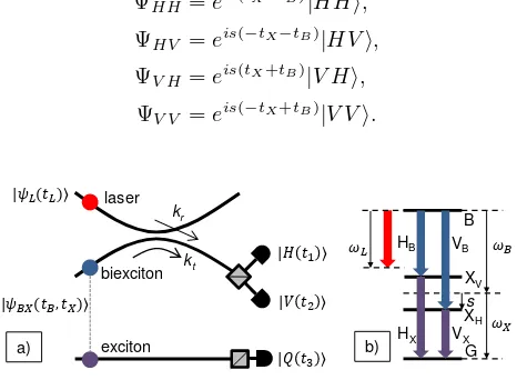
In our experiments, we employ a beamsplitter to com-bine laser photons with biexciton photons originating from an entangled-LED, as shown in figure 5(a). To con-serve biexciton photons from the entangled light source, the beamsplitter is highly imbalanced such that the transmission coefficient|kt| ≫ |kr|. Only photons
emerg-ing on the efficient arm of the beamsplitter are measured, so for simplicity, the transmission and reflection coeffi-cients of the beamsplitter, and phase change due to the coupling, are included within the amplitude and overall phase components of the laser and quantum dot wave-functionψL andψBX.
To begin, we define the laser and quantum dot states. In general, they are given by:
ψj =Aj(tj)Cj(tj)|Ψj(tj)i,
whereAj(tj) is the time dependent real amplitude,Cj(tj)
is the overall phase, and|Ψj(tj)ithe polarisation and any
polarisation dependent phase. The overall phase term is further defined as:
Cj(tj) =eiωjtjeiφj(tj).
The first exponent is coherent, and contributes to the final solutions only through detuning ofωjto the primary
frequenciesωB and ωX. Decoherence is represented by
random fluctuations of the phaseφjas a function of time
tj, such thathei[φj(tj)−φj(tj+∆)]i=e−|∆|/Tj, whereTj is
the coherence time of photonj[32, 33].
For the laser input state with polarization defined by real parametersaandb, we have:
ψL=AL(tL)CL(tL)|ΨLi, |ΨLi=cos(a)|Hi+eibsin(a)|Vi.
The output polarization state is:
|ΨQi=cos(x)|Hi+eiysin(x)|Vi.
For photon pairs from the quantum dot, we have: ψBX =ABX(tB, tX)CB(tB)CX(tX)|ΨBX(tB, tX)i.
The ideal quantum dot biphoton amplitude and state are given by
ABXe(tB, tX),
|ΨBXei= (eis(tX−tB)|HHi+e−is(tX−tB)|V Vi)/ √
2. In practice, however, the emission from the quantum dot is partially mixed. We approximate this with the amplitudeABXu(tB, tX) and equal mixture of the
polar-ization states:
ΨHH =eis(tX−tB)|HHi,
ΨHV =eis(−tX−tB)|HVi,
ΨV H =eis(tX+tB)|V Hi,
ΨV V =eis(−tX+tB)|V Vi.
laser
biexciton
exciton
kt
kr
VX
HB VB
B
XH
XV
HX
s
G
a) b)
Figure 5: (a) Schematic of quantum relay scheme. Laser and biexciton photons meet at a fiber optic coupler with transmis-sion and coupling amplitudeskt and kr, before direction by
[image:7.612.324.557.444.615.2]The joint amplitude of the electric field at the three photon detectors Z is given by the following equation, where four-photon contributions and higher are disre-garded due to their relatively small probability compared to three-photon events:
Z(t1, t2, t3) =hH ψL(t1)hV Q ψBX(t2, t3)i
+hV ψL(t2)ihHQ ψBX(t1, t3)i
+hHV ψLL(t1, t2)ihQ ψX(t3)i
+hHV Q|ψBBX(t1, t2, t3)i.
The first two terms are the desired three-photon ampli-tudes originating from a single laser, biexciton, and ex-citon photon. The third and fourth terms originate from two laser photons plus one exciton photon, and two biex-citon photons plus one exbiex-citon photon respectively.
The three-photon intensity Z(t1, t2, t3)Z∗(t1, t2, t3) is
evaluated and integrated over the arrival time of theX photont3, from which we drop the subscript for
conve-nience. Finally, we make substitutions of the form: ηjIj(tj) =A2j(tj),
ηjηkgjk(2)(tj, tk) =A2jk(tj, tk),
ηjηkηlg (3)
jkl(tj, tk, tl) =A2jkl(tj, tk, tl),
whereηj is the time averaged intensity of photonj, and
Ij(tj) the normalised intensity of photonj as a function
of time. The final expression for the third-order correla-tion is,
g(3)(τ2, τ3)∝
1 2cos
2(a)sin2(x)ˆ p 0
IL(t−τ2)gBXe(2) (t−τ3, t)dt
+1 2sin
2(a)cos2(x)ˆ p
0
IL(t−τ3)g(2)BXe(t−τ2, t)dt
+1
4sin(2a)sin(2x)e −|τ1|
TL− |τ1|
TB
×cos((ωB−ωL)τ1−s(τ3+τ2) +y+b)
×
ˆ p
0 q
(IL(t−τ2)IL(t−τ3)g(2)BXe(t−τ2, t)gBXe(2) (t−τ3, t)dt
+1 4cos
2(a)ˆ p 0
IL(t−τ2)gBXu(2) (t−τ3, t)dt
+1 4sin
2(a)ˆ p 0
IL(t−τ3)gBXu(2) (t−τ2, t)dt
+ηL ηB
1 4cos
2(a)sin2(a) ˆ p
0
g(2)LL(t−τ2, t−τ3)IX(t)dt
+ηB ηL
ˆ p
0
g(3)BBX(t−τ2, t−τ3, t)dt.
Note the final term containing gBBX(3) (t−τ2, t−τ3, t)
is evaluated by substitution with chains of two-photon correlations, for different ordering of the two biexciton and one exciton photons. This is justified as detection of the first photon places the system to a well-defined state, which serves as the starting point for a correlation to a second photon, which after detection again places the system into another well-defined state, which is the start-ing point with correlation to a third photon. A factor of 1/2 in the penultimate term accounts for the Poissonian statistics of the laser two-photon intensity.
Optimum teleportation conditions
The single laser photon envelopeILwas approximated
as a Gaussian function, which is a satisfactory approxi-mation of what we observe in experiment. Single biex-citon and exbiex-citon photon intensitiesIB(tB) and IX(tX)
were directly measured, and the fine-structure-splitting and biexciton coherence time determined from polar-ization dependent spectroscopy and single-photon in-terferograms respectively. Correlations were measured between biexciton and exciton photons to determine g(3)BX(tB, tX−tB) for co- and cross-linearly polarized
states. The entangled and unentangled biphoton frac-tionsg(2)BXeandg(2)BXuwere extracted from half the differ-ence between, and uncorrelated component of, these mea-surements respectively. Similarly correlations between pairs of biexciton photonsgBB(2)(t1, t2) were directly
mea-sured.
Note that imperfections in polarization recovery and timing jitter are well represented in the parameter data, as the same physical measurement system was used for their measurement as for teleportation. However, addi-tional jitter was added when evaluating the calculations to terms with discontinuities around zero delay. This fact, together with the lower time-averaged estimate of the coherence time compared to biexciton photons emit-ted in a single cycle, means that calculations are expecemit-ted to underestimate the relay fidelity slightly, as observed.
8
a) b)
[image:9.612.59.283.52.165.2]