Considering Machine Parameter and Inverter Nonlinearities
.
White Rose Research Online URL for this paper:
http://eprints.whiterose.ac.uk/93497/
Version: Accepted Version
Article:
Hoang, K.D. and Aorith, H.K.A. (2015) Online Control of IPMSM Drives for Traction
Applications Considering Machine Parameter and Inverter Nonlinearities. IEEE
Transactions on Transportation Electrification, 1 (4). 312 - 325. ISSN 2332-7782.
https://doi.org/10.1109/TTE.2015.2477469
[email protected] https://eprints.whiterose.ac.uk/
Reuse
Unless indicated otherwise, fulltext items are protected by copyright with all rights reserved. The copyright exception in section 29 of the Copyright, Designs and Patents Act 1988 allows the making of a single copy solely for the purpose of non-commercial research or private study within the limits of fair dealing. The publisher or other rights-holder may allow further reproduction and re-use of this version - refer to the White Rose Research Online record for this item. Where records identify the publisher as the copyright holder, users can verify any specific terms of use on the publisher’s website.
Takedown
If you consider content in White Rose Research Online to be in breach of UK law, please notify us by
Abstract—In this paper, an online control method of interior
permanent magnet synchronous machine (IPMSM) drives for traction applications considering machine parameter and inverter nonlinearities is presented. It is shown that the conventional technique using parameter information instantly extracted from premeasured parameter look-up tables (LUTs) only determines the local MTPA operating point associated with this specific parameter information without evaluating the global MTPA achievement. Therefore, global MTPA operation may not be achieved for conventional online control IPMSM drives with extreme nonlinear machine parameters (e.g. short-period overload operations). Thus, a model-based correction method using stator flux adjustment is proposed for an online quasi-global MTPA achievement. It is also proven that in the flux-weakening region, due to the inverter nonlinearities, a lower than expected maximum achievable torque for a demanded speed and a higher than expected current magnitude for a demanded torque may be obtained. Hence, an inverter nonlinearity compensation (INC) method exploiting the voltage feedback loop is introduced and its advantages over the conventional INC scheme are demonstrated. The proposed online control method is validated via measurements on a 10kW IPMSM.
Index Terms—Dead-time compensation, flux-weakening
control, interior permanent magnet synchronous machine, inverter nonlinearity, maximum torque per ampere control.
NOMENCLATURES
EMF Electro-motive force. FW Flux-weakening. FB Feedback. FF Feedforward.
INC Inverter nonlinearity compensation. INE Inverter nonlinearity effect. IVD Inverter voltage drop. LPF Low-pass filter. LUT Look-up table.
MTPA Maximum torque per ampere. OVL Overmodulation voltage limitation. PDC Pulse-based dead time compensation.
K. D. Hoang is with the Department of Electronic and Electrical Engineering, the University of Sheffield, Sheffield S1 3JD U.K. (email: [email protected]; [email protected]).
H. K A Aorith was with the Department of Electronic and Electrical Engineering, the University of Sheffield, Sheffield S1 3JD U.K. She is now with AECOM, Leeds, U.K. (email: [email protected]).
SVM Space vector modulation.
I. INTRODUCTION
Nterior permanent magnet synchronous machines (IPMSMs) are widely utilized in electric traction applications due to its high efficiency and wide flux-weakening (FW) capability [1]-[3]. However, IPMSM parameters are well-known for their highly nonlinear characteristics due to the magnetic saturation and cross-coupling effects [4], [5]. Thus, a control technique considering the machine parameter nonlinearities is essential for IPMSM drives employed for traction applications where short-period overload operations associated with extreme nonlinear machine parameters are typically required to provide the demanded acceleration or the climbing capability. Generally, the literature in this topic is very large. Since torque control mode drives are often required for traction applications [1], [3], [6]-[9], IPMSM drive under torque control mode [10]-[15] is the main focus of this paper.
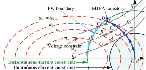
Typically, operation of IPMSM drives can be categorized into two modes [11]: the maximum torque per ampere (MTPA) control in the low-speed region to minimize the machine copper losses; and the flux-weakening (FW) control in the high-speed region to maintain the demanded voltage magnitude at the voltage boundary associated with the DC-link voltage and the selected modulation technique, Fig. 1. Based on the demanded torque, both the MTPA and the FW regions can be divided into two subregions [2]: the continuous subregion limited by the rated continuous current and the discontinuous subregion associated with the short-period overload operation, Fig. 1. For IPMSM drives, the FW operation can be achieved via two main techniques: the feedforward (FF)-based [10]-[13] and the feedback (FB)-based control schemes [14], [15]. In a FF-(FB)-based FW control IPMSM drive, the FW operating point (intersection point between a constant torque curve and a constant voltage curve, Fig. 1) is purposely defined from the demanded torque and the achievable stator flux magnitude under a demanded speed, Fig. 2(a). In a FB-based FW control IPMSM drive, for a demanded torque, the FW operating point is automatically determined by adjusting the MTPA stator flux reference via a voltage FB loop to maintain the demanded voltage at the hexagon boundary of an over-modulation voltage limitation
Online Control of IPMSM Drives for Traction
Applications Considering Machine Parameter
and Inverter Nonlinearities
K. D. Hoang,
Member
,
IEEE
,
and H. K A Aorith
(OVL) block, Fig. 2(b). Because of the unique intersection between a constant voltage curve and a constant torque curve, Fig. 1, the FW operation is always achieved via this voltage FB-based adjustment despite large parameter variations [16]. Due to this advantage, in this paper, the FB-based FW control method is considered for the tested IPMSM drive.
In practice, for IPMSM drives with machine parameter nonlinearities, predefined dq-axis current reference look-up tables (LUTs) computed offline from the premeasured nonlinear machine parameters with the demanded torque or power along with the demanded stator flux magnitude as their inputs are often utilized [10]-[15], Fig. 2. Although the LUT-based method is simple to be implemented, it requires offline iterative calculation, and cannot consider the parameter mismatches and variations [17], [18] during its operation. In addition, the iterative computation is always an extremely time-consuming process. On the other hand, online control techniques for IPMSM drives with nonlinear machine parameters were proposed in [19]-[22] where the parameter information is provided as an approximate linear function of q-axis current [19], premeasured nonlinear dq-axis stator flux linkage LUTs [20] or premeasured nonlinear machine parameter LUTs using measured dq-axis currents as their inputs [21], [22]. In comparison with the LUT-based method, online control technique provides flexibility for online
parameter estimation and update to enhance the drive system efficiency [17], [18]. In the low-speed region where a number of possible combinations of dq-axis currents and their relevant machine parameters can be employed for a demanded torque as shown in Fig. 1, the MTPA operation is often required to minimize machine copper losses. For a given set of machine stator flux linkage or parameter information instantly extracted from the premeasured LUTs, the Newton Raphson’s method was employed in [20], [22] and the Ferrari’s method was utilized in [21] for online implementation of the numerical MTPA solutions. It is noted that for IPMSMs with nonlinear parameters, each operating point in a constant torque curve shown in Fig. 1 is a combination of five specific values: dq-axis currents, dq-dq-axis inductances, and permanent magnet (PM) flux linkage. Thus, for a demanded torque, the conventional online methods in [20]-[22] only define the local MTPA operating point (dq-axis current references) associated with the specific parameter information (dq-axis inductances and PM flux linkage) instantly extracted from premeasured nonlinear LUTs. Without an iterative process which is impractical to be implemented online, these conventional online methods do not have the capability of evaluating the global MTPA operating point for a demanded torque. Basically, the nonlinear characteristics of IPMSMs’ parameters highly depend on values of the dq-axis currents [4], [5]. In the continuous operation subregion associated with low-operating currents, Fig. 1, where the nonlinear characteristics are often not significantly high, the equilibrium operating point in the constant torque curve under the conventional online methods may be located close to the global optimum operating point. Thus, in this subregion, the global MTPA operation may often be considered as achieved for the conventional online method [20]-[22]. However, in the discontinuous operation subregion associated with high-operating currents where the IPMSM parameters are well-known for their extreme nonlinear characteristics [4], [5], the global MTPA operation may not be obtained for the conventional online technique due to its incapability of evaluating the global MTPA operating point. Therefore, an online correction method to maintain a quasi-global MTPA achievement for online control IPMSM drives with extreme nonlinear parameters is one subject of this paper.
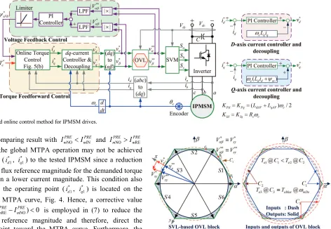
[image:3.612.50.296.52.170.2]On the other hand, for simplicity, the inverter nonlinearity effects (INEs) [23]-[32] on IPMSM drives are often neglected [10]-[15]. In the MTPA region where the allowable voltage is still sufficient for the current controllers to maintain the dq-axis current references under a demanded torque, neglecting of the INEs does not adversely affect the achievable torque which is the main concern for traction applications. However, in the FW region where the machine voltage magnitude is maintained at the ideal hexagon boundary, Fig. 2(b), there is always a mismatch between the ideal demand and the actual voltage applied to the tested machine due to the INEs. Consequently, both performance and efficiency of the IPMSM drive in the FW region may become deteriorated. Various compensation solutions for the INEs on electric drive systems in the low-speed region have been suggested [23]-[32]. Fig. 1. Operation regions of IPMSM drives employed for traction applications.
(a)
[image:3.612.48.298.194.393.2](b)
However, study of the INEs on FB-based FW control IPMSM drives in the FW region is quite limited [33] and this is another subject of this paper.
In this paper, an online FB-based FW control method of IPMSM drives for traction applications under torque control mode considering machine parameter and inverter nonlinearities is presented. It is shown that the global MTPA operation may not be achieved for conventional online IPMSM drives with extreme nonlinear machine parameters (e.g. in the discontinuous operation subregion) due to its incapability of determining the global MTPA operating point. Therefore, a model-based correction method using stator flux adjustment to maintain the equilibrium operating point very close to the global MTPA point for a quasi-global MTPA achievement is suggested and experimentally validated. It is also proven that in the FW region where the machine voltage is regulated at the ideal hexagon boundary via a voltage FB loop, due to the INEs, a lower than expected maximum achievable torque for a demanded speed and a higher than expected current magnitude for a demanded torque may be obtained. Thus, an inverter nonlinearity compensation (INC) scheme exploited the voltage FB loop adjustment is proposed. Compared with the previous study [33], in this paper, much more detail descriptions of the suggested INC scheme are presented and its advantages over the conventional INC scheme [26]-[32] are demonstrated.
II. ONLINE FB-BASED FW CONTROL OF IPMSMDRIVES WITH NONLINEAR PARAMETERS UNDER TORQUE CONTROL MODE
A. Online Control for IPMSM Drives with Nonlinear Machine Parameters under Torque Control Mode
The mathematical model of an IPMSM in the (dq) reference frame can be expressed as follows [22]:
sd
d s d e sq
d
v
R i
dt
ψ
ω ψ
=
−
+
; q s q e sd sqd
v R i
dt
ψ
ω ψ
= + + (1)
sd L id d m
ψ = +ψ ;
ψ
sq=L iq q;2 2
s sd sq
ψ = ψ +ψ (2)
3
[ ( ) ]
2
e m d q d q
T = pψ + L −L i i (3)
where vd,q, id,q, sd,sq, Ld,q are the transformed (dq) voltages,
currents, stator flux-linkages, and stator inductances, respectively; e is the electrical rotor speed; Rs is the stator
resistance; m is the permanent magnet flux linkage; s is the
stator flux magnitude; Te is the electromagnetic torque; and p
is the pole-pair number.
In the low-speed operating region, for a demanded torque, the MTPA control technique is often employed to minimize the machine copper losses [22].
2
2 4 2 2
( ) 0
3 3
e e
d q qMTPA m qMTPA
T T
L L i i
pψ p
− + − =
(4)
In a FB-based FW control IPMSM drive [14], [15], the dq-axis current references under both the MTPA and the FW operations are computed from the stator flux reference and the demanded torque, Fig. 2(b). Substituting (2) into (3) and solving leads to the mathematical relationship between the
d-axis current, the torque, and the stator flux magnitude [33].
4 3 2
4d 3d 2d 1d 0 0
a i +a i +a i +a i +a = (5)
wherea4 =L L2d( d −Lq)2,a3=2L Ld( d −Lq)(2Ld −Lq)ψm,
2 2 2 2
2 [(2 d q) 2 d( d q)] m ( d q) s
a = L −L + L L −L ψ − L −L ψ ,
2 2
1 2 m[(2 d q) m ( d q) s]
a = ψ L −L ψ − L −L ψ ,
4 2 2 2
0 m [2 e q / (3 )] m s
a =ψ T L p ψ ψ
+ − .
Since both (4) and (5) are 4th order polynomials, the Newton-Raphson iterative method can be employed [22], [33]. After (4) and (5) have been solved, relevant idMTPA for (4) and
relevant iq for (5) can be derived via the torque equation (3).
However, the machine parameters in (1) to (5) of the tested IPMSM are highly nonlinear and represented as functions of id
and iq for both Ld and Lq, and as a function of iq for m, Fig. 3.
These nonlinear parameters are obtained via finite element studies and then experimentally validated by the measurement method presented in [5]. It is noted that the continuous rated current of the tested IPMSM is 58.5(A) and the discontinuous maximum current is 118(A) for 200% capability of short-time overload operation (see Table I in Section IV for further details). As can be seen in Fig. 3, the tested IPMSM’s parameters become extreme nonlinearities in the
(a)
(b)
[image:4.612.312.568.47.424.2](c)
discontinuous operation subregion (high-operating currents). Conventionally, these nonlinear parameters can be stored into three separate LUTs with measured id and iq as the relevant
inputs to provide the instantaneous machine parameter information [21], [22], [33].
B. Global MTPA Achievement Problem of Conventional Online Control Technique
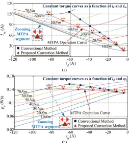
By iterating the nonlinear parameters shown in Fig. 3 together with relevant dq-axis currents, the tested IPMSM’s constant torque curves as a function of the current magnitude Im and d-axis current id; and as a function of the stator flux
magnitude s and id are respectively illustrated in Figs. 4(a)
and 4(b). It is noted that each operating point in a constant torque curve shown in Fig. 4 is a combination of five specific values: id, iq, Ld(id,iq), Lq(id,iq), and m(iq).Based on Fig. 4, two
general characteristics of IPMSM with parameter nonlinearities are outlined as follows
Remark 1: For a demanded torque in the low-speed region, a number of possible combinations of dq-axis currents together with their relevant machine parameters shown in Fig. 3 can be utilized, Fig. 4(a). Although only one unique combination can be employed to achieve the global MTPA operation, current magnitudes of this global MTPA point and the other combinations locating in the small segment around this global MTPA point (named as MTPA small segment) are almost similar (e.g. zooming of the 70Nm MTPA small segment). If the operating point is maintained within this MTPA small segment, a quasi-global MTPA operation with its current magnitude is almost similar to that of the actual global MTPA point can be achieved. Similar
phenomenon can be found in [5], [10], and [12] for IPMSMs with nonlinear parameters where almost similar maximum achievable torque can be obtained for operating points with a constant current magnitude and different current angles (i.e. different dq-axis current components with a constant current magnitude) located in the small segment around the global MTPA point.
Remark 2: Under a demanded torque, the reduction of the stator flux magnitude via increasing of d-axis current, Fig. 4(b), results in a parabolic trendline for the current magnitude of which the minimum point is the global MTPA point, Fig. 4(a). Thus, the flux reference variation within the MTPA small segment results in almost similar current magnitude (e.g. zooming of the 70Nm MTPA small segments). This phenomenon is simply based on the general demagnetization characteristic of IPMSMs.
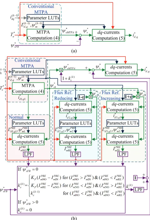
The conventional online technique for IPMSMs with nonlinear parameters under torque control mode is illustrated in Fig. 5(a), [20]-[22], [33]. Firstly, based on the measured currents (k 1)
d
i − and (k 1)
q
i − (values in the previous stage), the
relevant parameters L(dk1)
−
, L(qk 1)
−
, and ψm(k 1)
−
are extracted from the parameter LUTs, Fig. 3. These values are employed to compute the relevant dq-axis current references *
dMTPA
i ,
*
qMTPA
i , and the stator flux reference magnitude,
ψ
sMTPA* , underMTPA operation for the demanded torque, Te*, using (4).
Then, the demanded flux magnitude reference
* * *
s sMTPA sFB
ψ
=ψ
−ψ
, and Te* are used together with(k1)
d
L − ,
(k 1)
q
L − , and (k 1)
m
ψ −
in (5) to calculate the current references id*
and iq* applied to the tested IPMSM in the next-stage. In the
low-speed region,
ψ
*sFB=0 and therefore,* *
s sMTPA
ψ
=ψ
, * *d dMTPA
i =i , and iq*=i*qMTPA. However,
(k 1)
d
L − , (k 1)
q
L − , and (k 1)
m
ψ −
are the previous-stage parameter information. Both the current-stage and the next-stage parameter information is still unknown and may be different compared with (k1)
d
L − , (k1)
q L − ,
and ψm(k 1)
−
when applying id* and
*
q
i to the tested IPMSM due
to the parameter nonlinearities. Actually, it is impractical for online control techniques to determine the global MTPA operating point for a demanded torque via the iteration of entire parameters LUTs shown in Fig. 3 together with their relevant dq-axis currents due to its extremely time-consuming process. Thus, without the capability of determining the global MTPA operating point, the conventional method in Fig. 5(a) can only evaluate the local MTPA operating point associated with the set of machine parameters (k 1)
d
L − , L(qk 1)
−
, and (k 1)
m
ψ −
instantly extracted from the premeasured LUTs. In practice, for a demanded torque, evaluation of the conventional method in Fig. 5(a) is implemented with different set of machine parameters associated with the variation of dq-axis currents during the transient period until an equilibrium operating point in the demanded torque curve, Fig. 4, is obtained. For the continuous subregion, Fig.1, where the parameter nonlinear (a)
[image:5.612.48.301.47.327.2](b)
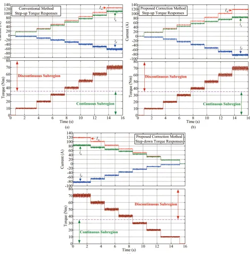
characteristics are often not significantly high, Fig. 3, this equilibrium operating point may be located close to the global MTPA operating point. Therefore, in this subregion, the global MTPA operation may be often considered as achieved [20]-[22]. However, in the discontinuous subregion, Fig. 1, where IPMSMs are well-known for their extreme nonlinear characteristics, Fig. 3, the global MTPA operation may not be obtained. To demonstrate this phenomenon, measured results of the tested IPMSM (35.5/70Nm continuous/discontinuous peak torque, see Section IV for further results) under the conventional online control method, Fig. 5(a), are also presented in Figs. 4(a) and 4(b). As can be seen, under short-period overload demanded torques (Te > 35.5Nm) associated
with extreme nonlinear parameters, Fig. 3, its equilibrium operating points are situated away from the MTPA operation curve. On the other hand, it is obvious inFig. 4 that when the operating point under a demanded torque is not situated in the MTPA operation curve, if the stator flux magnitude is adjusted along the demanded torque curve toward the MTPA small segment and then maintained within it, a quasi-global MTPA operation can be achieved. Based on this principle and the two aforementioned general characteristics of IPMSMs with parameter nonlinearities, a MTPA correction method is proposed, Fig. 5(b).
C. Proposed MTPA Correction Method for Online Control Technique
In Fig. 5(b), firstly, based on the conventional method, the relevant parameters L(dk 1)
− , L(qk 1)
−
, and ψm(k1)
−
of the measured
currents (k 1)
d
i − and (k 1)
q
i − are extracted from the parameter
LUTs and employed to compute the relevant local MTPA references *
1
d
i , * 1
q
i , and
ψ
s*1 for the demanded torque *e T via
(4). Then, * 1
d
i and * 1
q
i are utilized to extract relevant predicted
1
PRE d
L , LPREq1 , and PRE
1
m
ψ from the parameter LUTs. These values
are employed together with
ψ
*s1 and *e
T in (5) to predict the
normal current magnitude, NO
PRE m
I , obtained when applying ( * 1 d i , * 1 q
i ) to the tested IPMSM. Next,
ψ
*s1 is respectively reducedand increased by a small value (1% in this study) to obtain
* *
2 (1 ) 1
s s
ψ
= −ε ψ
andψ
s*3 = +(1ε ψ
) *s1. After that, *2
s
ψ
andψ
*s3 are respectively utilized together with L(dk1)− , L(qk 1)
−
, and ψm(k 1)
−
to compute the relevant current references ( * 2
d
i , iq*2) and ( * 3 d i , * 3 q
i ) for Te* via (5). Using previously described technique, the
predicted current magnitudes RE
PRE m
I and IN
PRE m
I obtained when
applying ( * 2
d
i , * 2
q
i ) and ( * 3
d
i , * 3
q
i ) to the tested IPMSM can be
respectively derived. Then, NO
PRE m
I , RE
PRE m
I , and IN
PRE m
I (filtered by first-order LPF-see the next Section) are compared together to define the corrective value kc for the stator flux reference as
shown in (6). If
ψ
sFB* =0NO IN NO IN NO RE
( )
RE NO NO IN NO RE
( 1)
NO IN NO RE
( ) for ( ) & ( )
= ( ) for ( ) & ( )
for ( ) & ( )
PRE PRE PRE PRE PRE PRE
P m m m m m m
k PRE PRE PRE PRE PRE PRE
c P m m m m m m
k PRE PRE PRE PRE
c m m m m
K I I I I I I
k K I I I I I I
k − I I I I
− > <
− < >
< <
(6a)
If
ψ
sFB* >0 ( )=0
k c
k (6b)
Under the proposed correction method, the stator flux reference for the quasi-global MTPA achievement is adjusted as
* ( ) *
1 (1 k )
sMTPA kc s
ψ = + ψ (7)
According to Figs. 4 and 5(b), in the low-speed region with *
0
sFB
ψ
= , the comparing result with NO INPRE PRE
m m
I >I and
NO RE
PRE PRE
m m
I <I indicates that the global MTPA operation may not
be achieved when applying ( * 1
d
i , * 1
q
i ) to the tested IPMSM as
an increase of the stator flux reference magnitude for the demanded torque may result in a lower current magnitude. This condition also implies that the operating point ( *
1
d
i , * 1
q
i ) is
located on the left of the MTPA curve, Fig. 4. Thus, a corrective value ( ) ( NO IN) 0
k PRE PRE
c P m m
k =K I −I > is utilized in (7) to increase the stator flux reference magnitude and therefore, lead the operating point toward the MTPA curve. On the other (a)
[image:6.612.52.300.47.411.2](b)
hand, the comparing result with NO IN
PRE PRE
m m
I <I and NO RE
PRE PRE
m m
I >I
shows that the global MTPA operation may not be achieved by applying ( *
1
d
i , * 1
q
i ) to the tested IPMSM since a reduction
of the stator flux reference magnitude for the demanded torque may result in a lower current magnitude. This condition also implies that the operating point ( *
1
d
i , * 1
q
i ) is located on the
right of the MTPA curve, Fig. 4. Hence, a corrective value ( )
RE NO
( ) 0
k PRE PRE
c P m m
k =K I −I < is employed in (7) to reduce the stator flux reference magnitude and therefore, direct the operating point toward the MTPA curve. Furthermore, the comparing result with NO IN
PRE PRE
m m
I <I and NO RE
PRE PRE
m m
I <I indicates that the instantaneous operating point is already located in the MTPA small segment shown in Fig. 4 as both further increasing or reducing of the stator flux reference magnitude for the demanded torque may result in a higher current magnitude. Thus, the corrective value is kept as constant with
( )k (k 1)
c c
k =k − for a quasi-global MTPA achievement with its current magnitude is almost similar to that of the actual global MTPA point, Fig. 4(a). In practice, values of Kp and in Fig.
5(b) are selected via a trial-and-error basic until a minimum current magnitude for the peak discountinuous torque can be achieved. To obtain a smoothed value kc, a LPF is employed.
It is noted that the proposed method in Fig. 5(b) can also be considered for ideal IPMSM drives with constant parameters neglecting the nonlinear characteristics. In the ideal case, as the MTPA operation is always achieved via solving (4), the proposed correction method is implemented with kc( )k =0. On the other hand, when the FW operation is activated with
* 0
sFB
ψ
> , the stator flux reference magnitude is regulated by the voltage FB loop, Fig. 2(b), not the proposed correction method. Thus, ( )k 0c
k = for
ψ
*sFB >0 as shown in (6b).D. Implementation of Proposed Online Control Method for IPMSM Drives with Nonlinear Parameters
The proposed online FB-based FW control scheme is presented in Fig. 6 where i*d and
*
q
i are computed based on
Fig. 5(b). For the PI current controller parameters, LdAV and
LqAV is respectively the average d- and q-axis inductance; c is
the controller cut-off frequency selected as two times of the tested IPMSM’s maximum speed (4500rpm). Based on the Space Vector Limit (SVL) technique [34], an OVL block is utilized to keep the voltage reference magnitude |Vαβ* | within the hexagon boundary associated with the measured DC-link voltage value, Fig. 7(a). Firstly, the voltage reference vector
* * j *
Vαβ =vα+ vβ is converted from the ( ) to the (xy) reference frame to obtain *
xy
V , using (8).
j
* * * *
j xy
xy x y
V v v V eαβ θ
−
= + = ;θxy = +[1 2(Si−1)]( / 6)π (8)
where Si is the sector in which Vαβ* is located, Fig. 7(a).
If *
( / 3)
x dc
v > V , *
xy
V is limited to **
xy
V as follows
** ** ** * *
j ( / 3)[1 j( / )]
xy x y dc y x
V =v + v = V + v v (9)
Then, Vxy** is transferred back to the ( ) reference frame
via (10) to provide the output voltage reference vector of the OVL block, V**
αβ.
j
** ** j ** ** xy
xy
Vαβ =vα + vβ =V eθ (10) When the inputvector *
Vαβ of the OVL block partly locates outside the hexagon boundary [dash-line segment a1-b1 of the locus C1 in Fig. 7(a)], the output vector Vαβ** of the OVL block
[image:7.612.96.568.50.376.2]is limited at the straight-line a1-b1 in the hexagon boundary via
Fig. 6. Proposed online control method for IPMSM drives.
(a) (b)
(8) to (10). In the ideal case, **
Vαβ and the voltage applied to the machine via the SVM block in Fig. 6 are identical. In the low-speed region, the OVL block is not activated and the IPMSM drive is operated under the proposed MTPA control method, Fig. 5(b). When the operating speed is increased, the voltage magnitude |V* |
αβ is increased accordingly until the
OVL block is activated. Consequently, the magnitude difference between |V* |
αβ and |Vαβ**| (filtered by first-order
LPF with cut-off frequency as c) is utilized to generate a
stator flux FB reference using the voltage FB loop as shown in Fig. 6 where a limiter is employed to maintain a positive FB value (
ψ
*sFB≥0). The voltage FB controller gains are obtained via a trial-and-error basic. Under the voltage FB loop adjustment, the stator flux referenceψ
s* is regulated using(11) until a new equilibrium voltage reference locus maintained at the OVL hexagon boundary is obtained. As a result, the FW operation is automatically achieved.
* * *
s sMTPA sFB
ψ
=ψ
−ψ
(11)In Fig. 7(b), the dash circle is the input and the solid locus is the equilibrium output of the OVL block for a demanded torque in the FW region. Under a demanded speed, the voltage reference circle is expanded in accordance with the increase of the demanded torque until its locus is totally outside the circumscribed circle of the hexagon boundary, e.g. the dash circle C3.
III. INES ON IPMSMDRIVES AND PROPOSED COMPENSATION METHOD
In practice, due to the INEs including the dead-time, the turn on/off delay-time, and the inverter voltage drop (IVD) effects [23]-[32],there is always a mismatch between the ideal demand and the actual voltage applied to the tested IPMSM. In this section, the INEs on IPMSM drives are studied and relevant compensation methods are proposed.
A. INEs on IPMSM Drives
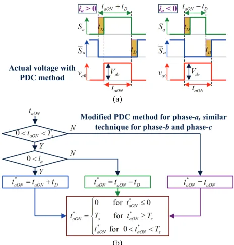
1) Dead-time Effects on IPMSM Drives
Basically, a dead-time timing tD is necessary to be
introduced at the rising edge of the switching signals delivered to the two switching devices in an inverter leg for shot-through prevention, Fig. 8(a), [23]-[32]. This dead-time timing, together with the switching device’s turn-on delay timing (tonDe) and turn-off delay timing (toffDe) result in a
dead-time mismatch ( va0De,b0De,c0De) [23]-[32] between the ideal
reference ( * 0, 0, 0
a b c
v ) and the actual phase-to-zero voltage
(va0,b0,c0) applied to the machine during a sampling period Ts,
(12). It is noted that these effects only exist on the inverter leg performing switching operation (e.g. with phase-a: 0 < taON <
Ts).
*
0 0 0
*
0 0 0
*
0 0 0
( )
( )
( )
a De a a a a
D OnDe OffDe
b De b b dc b b
s
c De c c c c
v v v sign i d
t t t
v v v V sign i d
T
v v v sign i d
D
+ −
D = − =
D
(12)
where , , , ,
, , , ,
1 for 0
0 for ( 0) ( )
a b cON s a b c
a b cON a b cON s
t T
d
t or t T
< <
= ==
In practice, value of (tOnDe-tOffDe) in (12) is very small
compared with tD and often neglected. During timing tD, the
phase-to-zero inverter leg voltage depends on the current direction as shown in Fig. 8(b) for the phase-a leg (va0).
2) IVD Effects on IPMSM Drives
In the aforementioned study of dead-time effect, the inverter switching devices are considered to be ideal. In practice, the inverter is nonlinear with the inverter voltage drops (IVDs) [23]-[32], represented for one inverter leg by a forward voltage drop, VF, connected in series with an on-state
resistance voltage drop, RONi [35] (for simplicity, the IVDs of
the switching device and the free-wheeling diode are assumed to be similar). For a balanced IPMSM with star-connected winding, the mismatch phase-to-neutral voltages in the ( ) reference frame, vIVD, IVD, due to the IVD effects are presented in (13), [30]. It is noted that values of vIVD, IVD depend on both the current value and the current direction.
(a)
(b)
Fig. 8. Dead-time effects on phase-a. (a) Ideal phase-to-zero voltage. (b) Actual phase-to-zero voltage due to dead-time effects.
[image:8.612.328.550.48.258.2](a) (b)
[image:8.612.314.564.288.413.2]1 1 1
2 2 2
3 3 3
0
2 2
anIVD IVD
bnIVD IVD
cnIVD v v
v v
v
α β
− − D
D
=D
D
− D
(13)
where
2 1 1 ( )
1 2 1 ( )
3
1 1 2 ( )
anIVD a a
F
bnIVD ON b b
cnIVD c c
v i sign i
V
v R i sign i
v i sign i
D − −
D = + − −
D − −
3) INEs on IPMSM Drives
Based on (12) and (13), due to the INEs, there is always a mismatch between the ideal and the actual voltages applied to the IPMSM drives. In the MTPA region where the allowable voltage is still sufficient for the current controllers to maintain the dq-axis current references, neglecting of the INEs does not adversely affect the achievable torque [26]-[32]. However, for the FB-based FW control drive in the FW region, Fig. 6, due to the INEs, a smaller actual hexagon boundary together with a smaller equilibrium voltage locus applied to the tested IPMSM compared with the ideal cases are obtained, Fig. 9. This issue results in a lower than expected maximum achievable torque for a demanded speed and a higher than expected current magnitude leading to extra copper losses for a demanded torque. As a result, both performance and efficiency of the IPMSM drive in the FW region may become deteriorated.
B. Proposed Inverter Nonlinearity Compensation (INC) Method for IPMSM Drives
Basically, the dead-time effects can be mitigated by varying the pulse timing [23], modifying the switching commutation [24], or combining of these two methods [25]. In the low-speed region where the allowable voltage is still sufficient, the full INEs can be compensated by introducing feedforward (FF) corrective values represented for the average disturbance voltages due to the INEs over one switching cycle into the voltage references [26]-[32]. In practice, these corrective values are obtained from the off-line measurement [26], the manufacturer datasheets [27], [28], or the online estimation techniques [29]-[32]. It is noted that the studies in [23]-[32] were proposed for machine drives in the low-speed region. Due to the zero-current clamp effects [28] in the extreme low-speed region, performances of the methods in [26]-[28] which depend on the current direction information may become deteriorated. On the other hand, the online estimation techniques do not rely on the inverter parameters and the current direction information [29]-[32]. However, accurate machine parameter information is essentially required. In addition, the online techniques are often based on the assumption that the tested machines are ideal with constant parameters and sinusoidal back-EMF waveforms and therefore, the disturbance voltages and the current harmonics are only contributed by the INEs. In practice, this assumption may be inconsistent for IPMSM drives with parameter nonlinearities; especially in the FW region where the regulation of the voltage magnitude at the hexagon boundary also results in high voltage and high current distortions. Thus,
the online compensation schemes for INEs may not be suitable for IPMSM drives in the FW region.
[image:9.612.323.555.47.290.2]In this paper, due to their different impact levels: at switching pulse-level as shown in (12) and at fundamental signal-level as presented in (13), the dead-time and the IVD effects are compensated separately, Figs. 10 and 11. Under the proposed inverter nonlinearity compensation (INC) methods, Fig. 11, the corrective values for the IVD effects (VF and RON)
in (13) are extracted from the manufacturer’s datasheets. Firstly, it was proven in [23] that by accordingly varying the pulse timing tON with a value tD based on the phase current
polarity at the beginning of each modulation period, the impacts of the dead-time effects can be mitigated, Fig. 10(a). This method named as Pulse-based Dead-time Compensation (PDC) was well demonstrated in the low-speed operation region. However, in the FW region, there are switching periods when only one inverter leg performs switching operation as discussed in [33], [36]-[38]. Thus, a modified scheme is introduced in Fig. 10(b) to ensure that in the FW region, the PDC method is only implemented on the inverter leg performing switching operation.
(a)
[image:9.612.47.284.52.169.2](b)
Fig. 10. Compensation for dead-time effects. (a). Phase-to-zero voltage with PDC scheme. (b) Flowchart of modified PDC scheme.
(a) (b)
[image:9.612.314.565.323.443.2]In addition, under well-known overmodulation techniques [36]-[38], when the voltage reference locus is only partly outside the hexagon boundary, Fig. 7(a), the remaining voltage allowances in the hexagon corners can be exploited to increase the modulation index. Based on this principle, vIVD, IVD in (13) can be conventionally added forward to the relevant voltage reference components as shown in Fig. 11(a) (named as FF-based INC method) [26]-[32] to increase the voltage magnitude applied to the tested machine using the remaining voltage allowances in the hexagon corners, Fig. 9(b), and therefore, mitigate the IVD effects. However, in a FB-based FW control drive, the FW operating point is automatically determined by the voltage FB loop as aforementioned. Thus, a new method named as FB-based INC scheme is presented in Fig. 11(b) where the IVD effects are mitigated by introducing vIVD, IVD in (13) into the relevant voltage FB references. Unlike that under the conventional FF-based method, the amended voltage references under the proposed FB-based INC method are automatically obtained via the voltage FB loop adjustment. According to Fig. 6, as the new voltage FB reference magnitude considering the IVD effects, **
|VαβINC|, is increased compared with |V**|
αβ , the stator flux feedback
ψ
*sFBis reduced. Therefore, the stator flux reference
ψ
*s is increasedvia (11) until a new equilibrium voltage reference with a larger locus is achieved. As a result, the IVD effects are mitigated.
It is noted that when the actual equilibrium voltage reference locus shown in Fig. 9(b) is fully outside the actual hexagon boundary, the remaining voltage allowances in the hexagon corners for mitigating the IVD effects are completely exploited. However, the separate dead-time effect compensation is still achievable via the modified PDC method, Figs. 10 and 11.
IV. EXPERIMENTAL RESULTS
The proposed online control method in Fig. 6 has been validated in a 5kW IPMSM designed for traction application with capability of short-time overload up to 200% rated torque, Fig. 12(a), and its parameters are shown in Table I [22], [33]. The tested IPMSM is coupled to a dynamometer (AVL) via a 200Nm rating in-line torque transducer, Magtrol TMHS 312, for torque measurement. A magnetic encoder (Renishaw RM44SC0011B20F2F10) is employed to provide the rotor position information. The drive system is illustrated in Fig. 12(b) where the proposed control algorithms are implemented by a dSPACE system, DS1005. The inverter is realized by an intelligent power module, Mitsubishi PM300CLA060, of which the forward voltage drop and on-state resistance obtained from the manufacturer’s datasheet is
1.1V and 0.01Ω, respectively. The dead-time and switching
frequency of the inverter is respectively set as 3µs and 8kHz. During testing, the speed of the employed IPMSM is maintained by the dynamometer controller and its demanded torque is controlled via the dSPACE Control Desk-Real Time Interface tool in the MATLAB/Simulink environment. A
precision power analyzer (Yokogawa WT3000, ±0.02% basic power accuracy) is used together with the in-line torque transducer to measure currents, voltages, torque, and efficiencies of the drive system, Fig. 12(c). All the measurements are implemented in the steady state to ensure the accurateness.
The measured voltage and current waveforms of the tested IPMSM drive under the proposed control methods for the MTPA (1200rpm, 60Nm) and the FW (4000rpm, 10Nm) operations is respectively shown in Figs. 13(a) and 13(b). The modulation index values in Fig. 13 [0.8102 in Fig. 13(a) and 0.941 in Fig. 13(b)] were evaluated with the actual DC-link voltage applied to the tested IPMSM considering the INEs presented in (12) and (13). The tested IPMSM is fully operated in the FW region with entire torque range when its operating speed is around 1600rpm [22]. Since the machine
(a)
(b)
[image:10.612.312.565.49.380.2](c)
Fig. 12. Experimental hardware setup [22], [33]. (a) IPMSM coupled to dynamometer via torque transducer. (b) Inverter and dSPACE control system platform. (c). Oscilloscope and power analyzer.
TABLE I
TESTED IPMSMPARAMETERS [22],[33]
DC link voltage 120(V)
[image:10.612.312.562.451.526.2]voltage in the FW region is regulated at the hexagon boundary, the current waveforms in Fig. 13(b) are disturbed and non-sinusoidal compared with Fig. 13(a). To demonstrate the proposed MTPA correction method, measurements of currents and relevant torques responding for step-up load changes up to 70Nm of the tested online control IPMSM drive in the MTPA control region (1200rpm) without and incorporating the proposed correction method, Figs. 5(a) and 5(b), are respectively presented in Figs. 14(a) and 14(b). Based on Fig. 14, a comparative study on currents values, id
and Im, for the tested online control IPMSM drive without and
incorporating the proposed correction method are illustrated in Figs. 15(a) and 15(b), respectively. It is noted that for a demanded torque, each relevant operating point under different control techniques is a combination of relevant dq-axis currents together with a specific set of relevant machine parameters in Fig. 3. These equilibrium operating points are achieved via evaluation of the employed control technique with different set of machine parameters associated with the variation of dq-axis currents during the transient period until an equilibrium state is reached. As can be seen in Figs. 14(a), 15(a), 15(b), and also already illustrated in Fig. 4(a), in the continuous operation subregion (Te < 35.5Nm) where machine
parameter nonlinearities are not significantly high, under the conventional online method, the equilibrium operating points are still situated close to the global MTPA points. However, when the demanded torque is increased up to the discontinuous operation subregion (Te > 35.5Nm) associated
with extreme nonlinear parameters, the equilibrium operating points under the conventional online method, due to its incapability of determining the global MTPA operating point, are situated away from the MTPA operation curve. On the other hand, by incorporating the proposed correction method, a quasi-global MTPA operation can be obtained for the tested online control IPMSM drive with its equilibrium operating points are maintained very close to the global MTPA points in
both continuous and discontinuous operation subregions, Figs. 4(a), 14(b), 15(a), and 15(b). Demanded currents associated with required torques under different control techniques are presented in Table II where it is shown that the proposed correction scheme can achieve almost similar current magnitude for each demanded torque as that with the offline LUT-based method. For further demonstrating the effects of the proposed correction method,the increase of copper losses in percentage of the tested online control IPMSM drive due to not incorporating the proposed technique is illustrated in Fig. 15(c). As can be seen, in the continuous subregion where the machine parameter nonlinearities are not significantly high, the increases in the current magnitudes, Fig. 15(b), and the relevant increase in the copper losses, Fig. 15(c), due to not incorporating the proposed method are considerably small (1.59% increase in the copper losses for 30Nm demanded torque). Therefore, in the continuous subregion, the global MTPA operation is often be considered as achieved for the conventional online methods [20]-[22]. Since the equilibrium state under the conventional online method without the capability of determining the global MTPA operating point is only achieved in a random manner, the increase of copper losses in the continuous subregion is varied for different demanded torques, Fig. 15(c). On the other hand, in the discontinuous subregion where the machine parameter characteristics are extremely nonlinear, without incorporating the proposed method, efficiency of the tested online control IPMSM drive may be significantly deteriorated by up to 12.69% increase in the copper losses at 70Nm demanded torque. Furthermore, measurements responding to step-up and step-down load changes respectively shown in Figs. 14(b) and 14(c) also well demonstrate the dynamic performance of the online control method incorporating the proposed correction scheme.
In the FW region, the main focus of this paper is the compensation for theINEs on the tested IPMSM drive using
[image:11.612.54.563.49.272.2](a) (b)
the proposed FB-based INC method. Thus, only selected results are presented. Further results of the tested online control IPMSM drive can be found in [22] and [33]. In Figs. 16(a) and 16(b), it is respectively shown that by incorporating the conventional FF-based INC method, Fig. 11(a), and the proposed FB-based INC method, Fig. 11(b), a lower current magnitude for a demanded torque at a demanded speed compared with neglecting INEs is obtained. On the other hand, comparison between Figs. 16(a) and 16(b) demonstrates the advantages of the proposed FB-based INC method over the conventional FF-based INC method in the FW region with a
higher achievable speed for a similar torque and current magnitude (e.g. at 10Nm, 85A), i.e. a higher achievable power for a similar current magnitude. Based on Fig. 16, copper loss reductions in percentage for the tested IPMSM in the FW region by incorporating the FF-based and the FB-based INC methods are respectively presented in Figs. 17(a) and 17(b). It is noted that the voltage allowances in the hexagon corners, which are essential for mitigating the IVD effects, are reduced when the equilibrium voltage locus is expanded due to the increase of the demanded torque under a demanded speed; or the increase of the demanded speed. Thus, the effectiveness of
(a) (b)
[image:12.612.57.563.44.558.2](c)
both the FF-based and the FB-based INC methods on copper loss reduction is reduced in accordance with the increase of the demanded torque or the demanded speed, Figs. 17(a) and 17(b). For the proposed FB-based INC method, under a
low-speed and low-torque operating condition (2000rpm, 5Nm), up to 7% copper loss reduction can be obtained, Fig. 17(b). However, at a high-speed operating condition (4500rpm, 20Nm), only 1.65% copper loss reduction can be achieved. In addition, the conventional FF-based INC method can only respectively obtain 5% copper loss reduction at 2000rpm, 5Nm and 1.2% copper loss reduction at 4500rpm, 20Nm, Fig. 17(a). On the other hand, under a demanded speed, when the voltage allowances in the hexagon corners are fully utilized, the separate compensation for the dead-time effect, Fig. 11, still can be achieved. It is shown that 1.5% maximum achievable torque can be obtained at 4500rpm (22.42Nm compared with 22.1Nm) by incorporating the proposed FB-based INC method, Fig. 18. The advantages of the FB-FB-based INC method over the conventional FF-based INC method with a higher achievable torque for a demanded speed in the FW region can also be observed in Fig. 18.
V. CONCLUSION
In this paper, an online FB-based FW control technique of IPMSM drives for traction applications under torque control mode considering machine parameter and inverter nonlinearities has been proposed and experimentally validated. It has been proven that global MTPA operation may not be achieved for IPMSM drives under the conventional online control method with extreme nonlinear machine parameters (e.g. in the discontinuous operation subregion) due to its incapability of determining the global MTPA operating point. Thus, a model-based MTPA correction method using the (a)
(b)
[image:13.612.264.562.47.345.2](c)
Fig. 15. Measured results of tested IPMSM drive under MTPA operation at 1200rpm, without and incorporating proposed correction method. (a). id values. (b). Im values. (c). Increase in copper losses (%) due to not incorporating proposed method.
TABLE II
DEMANDED CURRENTS UNDER DIFFERENT CONTROL METHODS
Te (Nm) Iteration Offline (A) Conventional Online (A)
Proposed Online (A)
id iq Im id iq Im id iq Im 10 -4.2 16.68 17.2 -4.09 16.76 17.26 -4.2 16.68 17.2 20 -13.6 31.2 34 -11.6 32.02 34.06 -12.8 31.49 34 30 -25 43.9 50.5 -20.18 46.73 50.91 -24.7 44.05 50.5 40 -37.6 55.5 67.04 -29.48 61.34 68.06 -37 55.98 67.1 50 -52.2 65.5 83.8 -39.39 76.35 85.91 -52.3 65.47 83.8 60 -67.8 74.61 100.81 -49.99 92.05 104.7 -68.2 74.36 100.9 70 -84 83.7 118.58 -61.6 109.8 125.9 -83.3 84.42 118.6
(a)
[image:13.612.53.326.51.494.2](b)
adjustment of the stator flux reference has been proposed and a quasi-global MTPA achievement has been presented.
It has been shown that in the FW region where the machine voltage magnitude is maintained at the ideal hexagon boundary, there is a mismatch between the ideal demand and the actual voltage applied to the machine due to the inverter nonlinearities. This issue causes a lower than expected maximum achievable torque for a demanded speed and a higher than expected current magnitude for a demanded torque. Therefore, a FB-based INC scheme exploiting the voltage FB loop has been suggested and its advantages over the conventional FF-based INC method have been demonstrated.
Future work to improve the proposed online control method
will include consideration of machine parameter estimation and update to enhance the drive system efficiency.
ACKNOWLEDGEMENT
The authors would like to thanks the anonymous reviewers for their valuable comments and suggestions that greatly contributed to improve the quality of this paper.
REFERENCES
[1] H. Nakai, H. Ohtani, E. Satoh, and Y. Inaguma, “Development and testing of the torque control for the permanent-magnet synchronous motor,” IEEE Trans. Ind. Electron., vol. 52, no. 3, pp. 800-806, Jun. 2005.
[2] G. Pellegrino, A. Vagati, P. Guglielmi, and B. Boazzo, “Performance comparison between surface-mounted and interior PM motor drives for electric vehicle application,” IEEE Trans. Ind. Electron., vol. 59, no. 2, pp. 803-811, Feb. 2012.
[3] T. Miyajima, H. Fujimoto, and M. Fujitsuna, “A precise model-based design of voltage phase controller for IPMSM,” IEEE Trans. Power Electron., vol. 28, no. 12, pp. 5655-5664, Dec. 2013.
[4] B. Stumberger, G. Stumberger, D. Dolinar, A. Hamler, and M. Trlep, “Evaluation of saturation and cross-magnetization effects in interior permanent magnet synchronous motor,” IEEE Trans. Ind. App., vol. 39, no. 5, pp. 1264-1271, Sep./Oct. 2003.
[5] K. M. Rahman and S. Hiti, “Identification of machine parameters of a synchronous machine,” IEEE Trans. Ind. Appl., vol. 41, no. 2, pp. 557-565, Mar./Apr. 2005.
[6] F. R. Salmasi, “Control strategies for hybrid electric vehicles: evolution, classification, comparison, and future trends,” IEEE Trans. Veh. Technol., vol 56, no. 5, pp. 2393-2404, Sep. 2007.
[7] M. Ceraolo, A. Donato, and G. Franceschi, “A general approach to energy optimization of hybrid electric vehicles,” IEEE Trans. Veh. Technol., vol. 57, no. 3, pp. 1433-1441, May. 2008.
[8] F. Yan, J. Wang, and K. Huang, “Hybrid electric vehicle model predictive control torque-split strategy incorporating engine transient characteristics,” IEEE Trans. Veh. Technol., vol. 61, no. 6, pp. 2458-2467, Jul. 2012.
[9] L. He, T. Shen, L. Yu, N. Feng, and J. Song, “A model predictive control based torque demand control approach for parallel hybrid powertrains,” IEEE Trans. Veh. Technol., vol. 62. no. 3, pp. 1041-1052, Mar. 2013.
[10] H. W. Kock, A. J. Rix, and M. J. Kamper, “Optimal torque control of synchronous machines based on finite-element analysis,” IEEE Trans. Ind. Electron., vol. 57, no. 1, pp. 413-419, Jan. 2010.
[11] B. Cheng and T. R. Tesch, “Torque feedforward control technique for permanent-magnet synchronous motors,” IEEE Trans. Ind. Electron., vol. 57, no. 3, pp. 969-974, Mar. 2010.
[12] S. Lee, Y. S. Jeong, Y. J. Kim, and S. Y. Jung, “Novel analysis and design methodology of interior permanent-magnet synchronous motor using newly adopted synthetic flux linkage,” IEEE Trans. Ind. Electron., vol. 58, no. 9, pp. 3806-3814, Sep. 2011.
[13] S. H. Kim and J. K. Seok, “Maximum voltage utilization of IPMSMs using modulating voltage scalability for automotive application,” IEEE Trans. Power Electron., vol. 28, no. 12, pp. 5639-5646, Dec. 2013. [14] B. H. Bea, N. Patel, S. Schulz, and S. K. Sul, “New field weakening
technique for high saliency interior permanent magnet motor,” in Conf. Rec. IEEE IAS Annu. Meeting, Oct. 2003, pp. 898-905.
[15] T. S. Kwon, G. Y. Choi, M. S. Kwak, and S. K. Sul, “Novel flux-weakening control of an IPMSM for quasi six-step operation,” IEEE Trans. Ind. Appl., vol. 44, no. 6, pp. 1722-1731, Nov./Dec. 2008. [16] T. S. Kwon and S. K. Sul, “Analysis of the effects of the parameter
variation on the flux weakening controller for improving torque capability,” in Proc. 23rd Annu. IEEE Appl. Power Electron. Conf. Expo. (APEC2008), 24-28 Feb. 2008, pp. 91-97.
[17] H. Kim, J. Hartwig, and R. D. Lorenz, “Using on-line parameter estimation to improve efficiency of IPM machine drives,” in Proc. IEEE Power. Electron. Spec. Conf., 2002, pp. 815-820.
(a)
[image:14.612.47.314.49.372.2](b)
Fig. 17. Cooper loss reduction of tested IPMSM drive under INC methods. (a). FF-based INC method. (b). FB-based INC method.
[18] Y. A. I. Mohamed and T. K. Lee, “Adaptive self-turning MTPA vector controller for IPMSM drive system,” IEEE Trans. Energy Convers., vol. 21, no. 3, pp. 636-644, Sep. 2006.
[19] S. Morimotor, M. Sanada, and Y. Takeda, “Effects and compensation of magnetic saturation in flux-weakening controlled permanent magnet synchronous motor drives,” IEEE Trans. Ind. Appl., vol. 30, no. 6, pp. 1632-1637, Nov./Dec. 1994.
[20] Y. Jeong, S. K. Sul, S. Hiti, and K. M. Rahman, “Online minimum copper loss control of an interior permanent magnet synchronous machine for automotive applications,” IEEE Trans. Ind. Appl., vol. 42, no. 5, pp. 1222-1229, Sep./Oct. 2006.
[21] S. Y. Jung, J. Hong, and K. Nam, “Current minimizing torque control of the IPMSM using Ferrari’s method,” IEEE Trans. Power Electron., vol. 28, no. 12, pp. 5603-5617, Dec. 2013.
[22] K. D Hoang, J. Wang, M. Cyriacks, A. Melkonyan, and K. Kriegel, “Feed-forward torque control of interior permanent magnet brushless AC drive for traction applications”, in Proc. IEEE Int. Conf. Elect. Mach. Drives, 2013, Chicago, US, May 12-15 2013, pp. 152-159. [23] D. Leggate and R. J. Kerkman, “Pulse-based dead-time compensator for
PWM voltage inverters,” IEEE Trans. Ind. Electron., vol. 44, no. 2, pp. 191-197, Apr. 1997.
[24] L. Chen and F. Z. Peng, “Dead-time elimination for voltage source inverters,” IEEE Trans. Power Electron., vol. 23, no. 2, pp. 574-580, Mar. 2008.
[25] C. Attaianese, V. Nardi, and G. Tomasso, “A novel SVM strategy for VSI dead-time-effect reduction,” IEEE Trans. Ind. Appl., vol. 41, no. 6, pp. 1667-1674, Nov./Dec. 2005.
[26] A. R. Munoz and T. A. Lipo, “On-line dead-time compensation technique for open-loop PWM-VSI drives,” IEEE Trans. Power Electron., vol. 14, no. 4, pp. 683-689, Jul. 1999.
[27] J. Holtz and J. Quan, “Sensorless vector control of induction motors at very low speed using a nonlinear inverter model and parameter identification,” IEEE Trans. Ind. Appl., vol. 38, no. 4, pp. 1087-1095, Jul./Aug. 2002.
[28] N. Urasaki, T. Senjyu, T. Kinjo, T. Funabashi, and H. Sekine, “Dead-time compensation strategy for permanent magnet synchronous motor drive taking zero current clamp and parasitic capacitance effects into account,” IEE Proc.-Electr. Power Appl., vol. 152, no. 4, pp. 845-853, Jul. 2005.
[29] H. S. Kim, H. T. Moon, and M. J. Youn, “On-line dead-time compensation method using disturbance observer,” IEEE Trans. Power Electron., vol. 18, no. 6, pp. 1336-1345, Nov. 2003.
[30] H. W. Kim, M. J. Youn, K. Y. Cho, and H. S. Kim, “Nonlinearity estimation and compensation of PWM VSI for PMSM under resistance and flux linkage uncertainty,” IEEE Trans. Cont. Sys. Tech., vol. 14. no. 4, pp. 589-601, Jul. 2006.
[31] S. Y. Kim, W. Lee, M. S. Rho, and S. Y. Park, “Effective dead-time compensation using a simple vectorial disturbance estimator in PMSM drives,” IEEE Trans. Ind. Electron., vol. 57, no. 5, pp. 1609-1614, May 2010.
[32] S. H. Hwang and J. M. Kim, “Dead time compensation method for voltage-fed PWM inverter,” IEEE Trans. Energy Convers., vol. 25, no. 1, pp. 1-10, Mar. 2010.
[33] K. D. Hoang, J. Wang, and H. Aorith, “Online feedback-based field weakening control of interior permanent magnet brushless AC drives for traction applications accounting for nonlinear inverter characteristics”, in Proc. IET Int. Conf. Power Electron. Mach. Drives, Apr. 8-10, 2014, pp. 1-6.
[34] R. Ottersten and J. Svensson, “ Vector current controlled voltage source converter-deadbeat control and saturation strategies,” IEEE Trans. Power Electron., vol. 17, no. 2, pp. 279-285, Mar. 2002.
[35] K. D. Hoang, Z. Q. Zhu, and M. P. Foster, “Direct torque control of permanent magnet brushless AC drive with single-phase open-circuit fault accounting for influence of inverter voltage drop,” IET Electric Power Applications, vol. 7, no. 5, pp. 369-380, May 2013.
[36] J. Holtz, W. Lotzkat, and A. M. Khambadkone, “On continuous control of PWM inverters in the overmodulation range including the six-step mode,” IEEE Trans. Power Electron., vol. 8, no. 4, pp. 546-553, Oct. 1992.
[37] D. C. Lee and G. M. Lee, “A novel overmodulation technique for space-vector PWM inverters,” IEEE Trans. Power Electron., vol. 13, no. 6, pp. 1144-1151, Nov. 1998.
[38] D. G. Holmes and T. A. Lipo, Pulse width modulation for power converters: Principle and Practice, New York: Willey-IEEE Press, 2003.
Khoa Dang Hoang (S’10-M’12) received the
B.Eng. and M.Sc.(Eng.) degrees from Ho Chi Minh City University of Technology (HCMUT), Ho Chi Minh City, Vietnam, in 2002 and 2005, respectively, and the Ph.D. degree from the University of Sheffield, Sheffield, United Kingdom, in 2011, all in electrical and electronics engineering.
Since 2011, he is working as a post-doctoral Research Associate at the University of Sheffield under several projects focusing on drive-train design and control for the next generation electric vehicles. His key research interests include power conversion, advanced control techniques for electrical drives, and analysis and design of electrical machines.
Hawa K A Aorith received the B.Eng degree in
electrical engineering from Garyounis University, Benhgazi City, Libya, in 1996, the M.Eng degree in automatic control from Tabbin Institute for Metallugrica Studies, Cairo, Egypt, in 2005, and the Ph.D. degree in electrical and electronic engineering from the University of Sheffield, Sheffield, United Kingdom, in 2014.
![Fig. 3. Nonlinear parameters of tested IPMSM [22], [33]. (a) Ld as a function of id and iq](https://thumb-us.123doks.com/thumbv2/123dok_us/7886569.185224/4.612.312.568.47.424/fig-nonlinear-parameters-tested-ipmsm-ld-function-id.webp)

![TABLE TESTED IPMSMI PARAMETERS [22], [33]](https://thumb-us.123doks.com/thumbv2/123dok_us/7886569.185224/10.612.312.562.451.526/table-tested-ipmsmi-parameters.webp)