This is a repository copy of Characterization of the Structural Environment of Dithionate Ions Associated with Their Role in the Crystal Habit Modification of Sodium Chlorate. White Rose Research Online URL for this paper:
http://eprints.whiterose.ac.uk/133237/ Version: Supplemental Material
Article:
Lan, Z, Calligaris, GA, de Menezes, AS et al. (4 more authors) (2018) Characterization of the Structural Environment of Dithionate Ions Associated with Their Role in the Crystal Habit Modification of Sodium Chlorate. Crystal Growth & Design, 18 (6). pp. 3328-3338. ISSN 1528-7483
https://doi.org/10.1021/acs.cgd.7b01770
© 2018 American Chemical Society. This is an author produced version of a paper published in Crystal Growth & Design. Uploaded in accordance with the publisher's self-archiving policy.
[email protected] https://eprints.whiterose.ac.uk/
Reuse
Items deposited in White Rose Research Online are protected by copyright, with all rights reserved unless indicated otherwise. They may be downloaded and/or printed for private study, or other acts as permitted by national copyright laws. The publisher or other rights holders may allow further reproduction and re-use of the full text version. This is indicated by the licence information on the White Rose Research Online record for the item.
Takedown
If you consider content in White Rose Research Online to be in breach of UK law, please notify us by
ヱ
SUPPLEMENTARY MATERIAL
Characterization of the Structural Environment of
Dithionate Ions Associated with their Role in the
Crystal Habit Modification of Sodium Chlorate
Zhipeng Lan,1, Guilherme A. Calligaris,2 Alan S. de Menezes,2, ‡
Adenilson O. dos Santos,3 Xiaojun Lai,1 Lisandro P. Cardoso2 and Kevin J. Roberts1
Background information on the techniques of Extended X-Ray Absorption Fine
Structure (EXAFS) and X-Ray Multiple Diffraction (XRMD) is provided here.
A1. EXTENDED X-RAY ABSORPTION FINE STRUCTURE
When material undergo electromagnetic (EM) waves absorption it normally experiences a
smooth dependence of its linear absorption coefficient in respect of the incident wave
energy E. However, it abruptly suffers discontinuities at some energies that corresponds to
the X-rays range in the EM spectrum, and this phenomenon is known as Absorption Edges.
A careful measure of both incident and transmitted intensity of X-rays which pass thru the
material makes visible all the small features of a so call X-rays Absorption Fine Structure
(XAFS), as seem in the Figure A1.1. At same time, XAFS can be summarized as two
defined regions known as ray Absorption Near-Edge Structure (XANES) and Extended
ヲ
Figure A1.1 A general XAFS profile highlighting the two regions of XANES and EXAFS.
EXAFS usually are defined after ~50 eV from the absorption edge and extends up to 1000
eV more, as long the oscillations persist.
The observed oscillations in a EXAFS measure arises from the interference of an
outward-propagating spherical wave (described by an ejected photoelectron) centered in
the absorbing element (absorbing atom) with the backscattered wave from a neighbor atom
(scattering atom). In Quantum Mechanics this process is usually referred as the
interference in the final-state wave functions. The energy of the photoelectron depends on
the difference of the incident EM wave energy E and the absorption energy E0, and same
do its wavelength that is described as
, (A1.1)
where h is the Planck’s constant and m the electron mass. The related wave number k can
be written as
ン
and therefore has unit of Å-1.
Because of such interference, the linear absorption coefficient of an atom from the
studied material, i.e. the experimental , can be described in terms of k and the linear
absorption coefficient 0 of a free atom of the same element as
, (A1.3)
where (k) describes the EXAFS oscillation. By assuming only dipole interactions between
the absorbing element and the scattered wave, neglecting incident beam polarization and
single scattering of a ~50 eV (or higher) photoelectron, the expression of the EXAFS signal
is given by1
sin , (A1.4)
, (A1.5)
exp exp , (A1.6)
where the term 2kRj is the sine function argument that results from the phase of a
photoelectron which described the path of leaving the absorbing atom and return as
backscattered from a neighboring atom positioned at Rj. The other phase shift j(k)
describes the phase-shift of the absorber atom and the phase-shift of the jth backscattering
atom. Aj(k) is the amplitude term defined by Nj atoms of each shell and the scattering
complex function magnitude fj(k). S02 is an amplitude reduction factor arising from many
body effects. Both j(k) and fj(k) depends on the atomic number Zj. The exponential
ヴ
which is related to the photoelectron mean free path e. The second exponential decay is
defined in terms of the likewise a Debye-Waller parameter, j2 and describes the thermal
contribution that disturbs the absorbing and scattering atoms original positions.
Original data is normalized based on the first peak after the absorption edge, which
in turn is evaluated by a step function. Post-edge region background is described by a
spline line and its difference between the experimental curve defines the (k). The obtained
result is plotted in the k space and modern programs based on FEFF (stands for feff(k,r), an
effective scattering amplitude), such as Demeter suite2, is used to fit (k). Fitting data
before doing a Fourier transform (FT) helps avoid Fourier filtering issues. Only then original
data and best fit are transformed to the real space “r” to a radial structure function.
Gaussian distribution (based on parameter) describes the radial position of the
neighboring atoms from the absorbing element.
XAFS is being widely applied in determining the chemical state and local atomic
environment of a specific atom by tuning the incident X-ray energy near to its absorption
edges. In the study of chemical bonds in different sulphur compounds is possible to
highlight the work by Sekiyama et. al.3. The polarization from synchrotron sources can also
provide the necessary tool to the determine the orientation of chemical bonds, as
demonstrated by Tyson et al. by verify the electronic structure and molecular orientation of
S2O32- and S2O62- in ionic crystals4 and Yano et al. by determining the orientation of Mn-O
and Mn-N bonds in complex compounds5.
A2. X-RAY MULTIPLE DIFFRACTION
The multiple diffraction phenomenon occurs when an incident beam simultaneously
satisfies Bragg’s law for more than one set of lattice planes within the crystal. X-Ray
ヵ
primary reciprocal lattice vector HP, to diffract the incident beam SO into the primary beam
SP by adjusting the angle . Then, by rotating the azimuthal angle () the sample revolute
around HP while monitoring the intensity of the primary diffracted beam Iprimary. During the
axis rotation, at certain specific angular positions, other crystallographic planes called
secondary planes (hSkSlS) (related to the secondary reciprocal lattice vector HS) will also
satisfy diffraction conditions and generates the secondary beam SS in a distinct direction
from that of the SP beam. The SS beam will be reflected back into the same direction as that
of the SP by interaction with another coupling plane (hCkClC), coupling beam SC, and
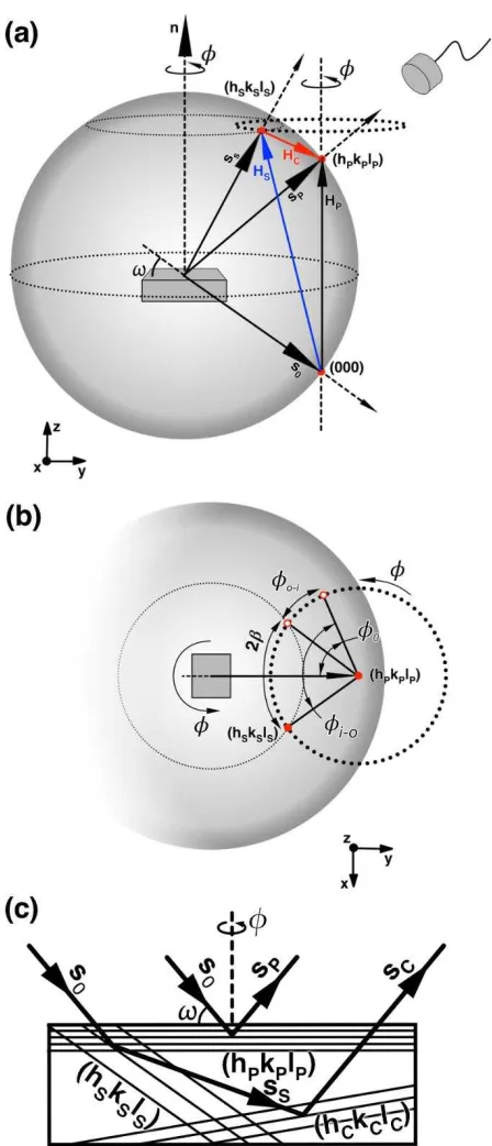
scattering vector HC. An overview of this process in shown in Figure A2.1(a) using the
Ewald sphere representation for diffraction conditions.
Based on this, secondary reflections can touch the Ewald sphere two times for each
full revolution of the axis, from outside to inside (angle o-i) and vice-versa (angle i-o) with
respect to a reference angle 0. The interaction between primary and secondary beams
appears in the measure of Iprimary versus , which is referred to as a Renninger Scan6 (RS),
as positive (Umweganregung) and negative (Aufhellung) peaks. Those peaks can appear in
pairs describing a symmetry mirror with respect to the chosen primary vector and the
angular distance 2 between o-i and i-o. Figure A2.1(b) describes this angles. Such peaks
represent energy transfer from the secondary beam into the path of the primary diffraction
(positive peak), or vice versa (negative peak), with the symmetry mirror being established
by the rotation when the secondary reciprocal lattice points enter and leave the Ewald
sphere. Therefore, in a RS one can clearly observe the position and intensity distributions
of these symmetry mirrors and these features are essential for most of the applications
using the RS XRMD technique. The overall shape of a RS diffraction peak profile as a
function of also provides a good indication on regards crystallographic symmetry and
ヶ
e.g. due to (say) a tetragonal distortion in epitaxial layers7 whilst an increase in peak width
can indicate a reduction in crystal quality.8 When a peak in the RS represents an interaction
of the incident, primary and one secondary beam, it shows up as a three-beam peak (or
three-beam case). One can also have two or more secondary beams interacting
simultaneously.
Figure A2.1(c) represents S0, SP, SS, and SC in the real space together with the
sample and the related planes in a generic XRMD case. Particularly, a special three-beam
XRMD case, called Bragg-Surface Diffraction (BSD),9 appears when the secondary beam
propagates parallel to the crystal surface under an extremely asymmetric diffraction
geometry. The BSD beams are of particular interest in this work that they carry information
regarding the crystallography of the sample surface region (and interfaces when they occur)
which is most useful for studying the structural impact of impurity incorporation at the
growing crystal surface.10, 11 The XRMD technique’s ability to characterize lattice strain
fields at the interfaces has been applied e.g. to epilayer/substrate in semiconductor
systems revealing a depth penetration resolution of about 2 Å and with enough sensitivity to
Α
Figure A2.1 (a) XRMD phenomena represented using the Ewald sphere, showing S0:
(000), SP: (hPkPlP) and SS: (hSkSlS) in a general 3-beam case. Scattering vectors HP, HS and
HC are also shown. (b) A top view of the axis rotation showing the 2, o-i, i-o angles
between the entrance and exit of the (hSkSlS) reciprocal lattice point. (c) A side view in the
[image:8.595.187.411.75.596.2]Β
Also, in the XRMD technique, complementary and additional information regarding
crystalline quality can be obtained from the detailed analysis of the exact multiple diffraction
condition, through the : mapping8. This method involves coupled scans of , the
incident angle, with respect to the diffraction lattice planes and , the azimuthal rotation
angle with respect to the primary reflection vector. In the mapping process, is scanned
within a certain range at discrete positions as identified by tailoring an exact : angular
for an observed multiple-beam diffraction position. Therefore, this mapping produces a
three-dimensional plot of the primary intensity versus and in a coupled way that the
crystalline perfection can be evaluate by taking the full width half maximum (FWHM) values
from and scans. When a BSD case is analyzed, the mapping can be related to the
mosaic spread along the perpendicular and in-plane crystallographic directions,
respectively.13
The indexation of a XRMD case is shown as
(000)(hPkPlP)(hS1kS1lS1)(hS2kS2lS2)…(hSnkSnlSn). So, a general 3-beam case has the incident
(000), one primary and one secondary beam. The coupling plane can be obtained by the
relation
hP=hS+hC kP=kS+kC lP=lS+lC
, and .
(A2.1)
The utility of XRMD in material science has been previously demonstrated in terms
of investigating the subtle changes in the crystal lattices under the application of an external
electric field, allowing in turn the determination of piezoelectric coefficients of single
crystals.14, 15 This technique was also used to study the impurity incorporation mechanism,
crystal perfection and habit modification of Mn3+ ion doped KDP crystals.10, 11, 16 In
Γ
between mosaic and nearly perfect crystals and the technique has been demonstrated to
be sensitive enough to analyze lattice strain perpendicular and parallel to the crystal
surfaces.8, 17
References
(1) Bunker, G., Introduction to XAFS : a practical guide to X-ray absorption fine structure spectroscopy. Cambridge University Press: Cambridge; New York, 2010.
(2) Ravel, B.; Newville, M., ATHENA, ARTEMIS, HEPHAESTUS: data analysis for X-ray absorption spectroscopy using IFEFFIT. Journal of Synchrotron Radiation 2005, 12, (4), 537-541.
(3) Sekiyama, H.; Kosugi, N.; Kuroda, H.; Ohta, T., Sulfur K-edge absorption spectra of Na2SO4, Na2SO3, Na2S2O3, and Na2S2Ox (x=5-8). Bull. Chem. Soc. Jpn. 1986, 59, (2), 575-579.
(4) Tyson, T. A.; Roe, A. L.; Frank, P.; Hodgson, K. O.; Hedman, B., Polarized experimental and theoretical \textit{K} -edge x-ray absorption studies of ${\mathrm{SO}}_{4}^{2\mathrm{-}}$, ${\mathrm{ClO}}_{3}^{\mathrm{-}}$,
${\mathrm{S}}_{2}$${\mathrm{O}}_{3}^{2\mathrm{-}}$, and
${\mathrm{S}}_{2}$${\mathrm{O}}_{6}^{2\mathrm{-}}$. Physical Review B 1989, 39, (10), 6305-6315.
(5) Yano, J.; Robblee, J.; Pushkar, Y.; Marcus, M. A.; Bendix, J.; Workman, J. M.; Collins, T. J.; Solomon, E. I.; DeBeer George, S.; Yachandra, V. K., Polarized X-ray Absorption Spectroscopy of Single-Crystal Mn(V) Complexes Relevant to the Oxygen-Evolving Complex of Photosystem II. Journal of the American Chemical Society 2007, 129, (43), 12989-13000.
(6) Renninger, M., „Umweganregung“, eine bisher unbeachtete
Wechselwirkungserscheinung bei Raumgitterinterferenzen. Zeitschrift für Physik A Hadrons and Nuclei 1937, 106, (3), 141-176.
(7) de Menezes, A. S.; dos Santos, A. O.; Almeida, J. M. A.; Bortoleto, J. R. R.; Cotta, M. A.; Morelhão, S. L.; Cardoso, L. P., Direct Observation of Tetragonal Distortion in Epitaxial Structures through Secondary Peak Split in a Synchrotron Radiation Renninger Scan. Crystal Growth & Design 2010, 10, (8), 3436-3441.
(8) Morelhão, S. L.; Cardoso, L. P., X-ray Multiple Diffraction Phenomenon in the Evaluation of Semiconductor Crystalline Perfection. Journal of Applied Crystallography 1996, 29, (4), 446-456.
(9) Morelhão, S. L.; Cardoso, L. P., Structural properties of heteroepitaxial systems using hybrid multiple diffraction in Renninger scans. Journal of Applied Physics 1993, 73, (9), 4218-4226.
(10) Lai, X.; Roberts, K. J.; Avanci, L. H.; Cardoso, L. P.; Sasaki, J. M., Habit modification of nearly perfect single crystals of potassium dihydrogen phosphate (KDP) by trivalent manganese ions studied using synchrotron radiation X-ray multiple diffraction in Renninger scanning mode. Journal of Applied Crystallography 2003, 36, 1230-1235. (11) Remédios, C. M. R.; dos Santos, A. O.; Lai, X.; Roberts, K. J.; Moreira, S. G. C.;
ヱヰ
(12) Sun, W. C.; Chang, H. C.; Wu, B. K.; Chen, Y. R.; Chu, C. H.; Chang, S. L.; Hong, M.; Tang, M. T.; Stetsko, Y. P., Measuring interface strains at the atomic resolution in depth using x-ray Bragg-surface diffraction. Applied Physics Letters 2006, 89, (9), 091915.
(13) Avanci, L. H.; Hayashi, M. A.; Cardoso, L. P.; Morelhao, S. L.; Riesz, F.; Rakennus, K.; Hakkarainen, T., Mapping of Bragg-surface diffraction of InP/GaAs(100) structure. Journal of Crystal Growth 1998, 188, (1-4), 220-224.
(14) Avanci, L. H.; Cardoso, L. P.; Girdwood, S. E.; Pugh, D.; Sherwood, J. N.; Roberts, K. J., Piezoelectric coefficients of mNA organic nonlinear optical material using synchrotron X-ray multiple diffraction. Physical Review Letters 1998, 81, (24), 5426-5429.
(15) Avanci, L. H.; Cardoso, L. P.; Sasaki, J. M.; Girdwood, S. E.; Roberts, K. J.; Pugh, D.; Sherwood, J. N., Synchrotron-radiation x-ray multiple diffraction applied to the study of electric-field-induced strain in an organic nonlinear optical material. Physical Review B
2000, 61, (10), 6507-6514.
(16) Remédios, C. M. R.; Paraguassu, W.; Freire, P. T. C.; Mendes, J.; Sasaki, J. M.; Melo, F. E. A., Temperature studies of KH2PO4 : Mn crystals using x-ray diffraction and polarized Raman scattering. Physical Review B 2005, 72, (1), 014121.