International Journal of Innovative Technology and Exploring Engineering (IJITEE) ISSN: 2278-3075, Volume-8 Issue-9, July 2019
Abstract: Power conveyance potentiality for series and parallel allied battery-packages are constrained by the wickedest cell of the string. Every cell contains marginally dissimilar capability and terminal voltage because of industrialized acceptances and functional situations. During charging or discharging progression, the charge status of the cell strings become imbalanced and incline to loss equalization. Therefore, the enthusiasm of this paper is to design an active charge balancing system for Lithium-ion battery pack with the help of online state of charge (SOC) estimation technique. A Battery Management System (BMS) is modeled by means of controlling the SOC of the cells to upsurge the efficacy of rechargeable batteries. The capacity of each cell is calculated by dint of SOC function estimated as a result of Backpropagation Neural Network (BPNN) algorithm through four switched DC/DC Buck-Boost converter. The simulation results confirm that the designed BMS can synchronize the cell equalization via curtailing the SOC estimation error (RMSE 1.20%) productively.
Index Terms: Active Cell balancing, Battery Management System, Battery modeling, SOC estimation.
I. INTRODUCTION
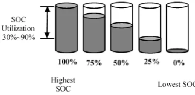
Smart grids and Electric vehicles (EVs) are turning out to be widely held owing to the increment of atmospheric apprehensions and deficiency of fossil fuels. As a perilous condition of the energy involving machineries, battery energy storage system (BESS) performs an indispensable role to provide power source and enhance the stowage strength [1]. Nevertheless, the BESS struggles with the variation of cell-to-cell parameter inconsistencies as well as these factors affect the battery cells life-time undesirability. To fix this delinquencies, BMS is entitled as the intellect of a battery pack that can monitor the battery voltage, current, temperature, SOC et al. in an attempt to retain cells in the interior of safe operational ranges. The leading purpose of BMS is to protect the cells from over-charging or deep-discharging to lengthen the battery life cycle [2],[3]. Generally, cells which are existent in series connection with different SOC levels, limits the battery-pack efficiency during charging and discharging conditions. As demonstrated in Fig.1, cells with the highest and lowest labeled SOC becomes over-charge and deep-discharge firstly neglecting others at charging and discharging period respectively[4].
Revised Manuscript Received on July 06, 2019.
Ohirul Qays, Electrical and Electronic Engineering, Universiti Malaysia Sarawak, Samarahan, Malaysia.
Yonis Buswig, Electrical and Electronic Engineering, Universiti Malaysia Sarawak, Samarahan, Malaysia.
[image:1.595.318.519.197.295.2]Martin Anyi, Electrical and Electronic Engineering, Universiti Malaysia Sarawak, Samarahan, Malaysia.
Fig. 1 Diagram of the cells with unbalanced state-of-charge.
To achieve reckless equalization efficiency for series-connected Lithium-ion batteries, Chen et al. [5] hired Multi-winding transformer to moderate the driving circuit quantities. Knap et al. [6] classified the charge equilibrium techniques into two main classifications: Passive and active charge equalization. The passive method disperses energy from overcharged cells by attaching a resistor. On the other hand, active cell balancing method agree to collect or allocate energy from higher ones to lower ones. Consequently, active charge balancing method can decline the power losses and battery cooling necessities [7],[8]. Typically, Open circuit voltage (OCV), terminal voltage and SOC are chosen as a parameter of charge equalization technique. But the instability of OCV and terminal voltage marks the system-inefficiency enormously comparing to SOC function. Furthermore, the use of SOC variable can be governed by the accuracy of SOC estimation method for every single cell. Among the SOC estimation techniques, adaptive method especially Artificial Neural Network (ANN) is the most popular and accurate method because of its self-processing characteristics [9]. BMS observes the battery condition by estimating SOC for each cell and transfers the directions via DC/DC converter according to its requirements [10],[11]. In this paper, an active cell balancing topology based on SOC estimation is accomplished standing on BPNN algorithm as well as a DC/DC buck-boost converter is engaged for each cell to observe the charge equilibrium scheme. The remainder of this paper is structured as follows: The previous related work is presented in section 2. In section 3, the proposed methodology is explained descriptively. Numerical simulation and a brief discussion for the proposed method is demonstrated in section 4. In the last section 5, the conclusion of this paper is drawn.
Active Cell Balancing Control Method for
Series-Connected Lithium-Ion Battery
Active Cell Balancing Control Method for Series-Connected Lithium-Ion Battery
2425
Published By:
Blue Eyes Intelligence Engineering Retrieval Number: I8905078919/19©BEIESP
DOI:10.35940/ijitee.I8905.078919
II. RELATED WORK
The series cell sequences decrease the capability of entire battery pack due to any weaken battery cell of the strings. To improve the efficiency of the storage system, [2] proposed an improved BMS for LIB pack to regulate the temperature, SOC and SOH of the cells by the dual active bridge DC/DC converter. Extended Kalman Filter (EKF) and active cell balancing technique was implemented to improve the accuracy of the SOC estimation and charge equalization respectively where the SOC variation was obtained only 3%. In the long run, the fragile cell was recommended to avoid from the string if the cell eminence can’t be improved finally. A significant parameter named Residual Available Energy (RAE) can be utilized to measure the departure of energy from the battery pack. Depending on this statement, [3] experimented active cell balancing equalization technique on eight capacitive battery cells which were preferred from 95 aged batteries commencing a company’s EV. The internal resistance and capacity of every single cell were applied to compute the status of RAE for entire battery pack where the energy employment improved nearly 10.97%. Though the error between the experimental and simulation was obtained less than 1%, only, the load was assumed as static for the projected system. Finally, a compensation between the improved RAE and energy forfeiture was suggested for further research to boost the adeptness of the stratagem. After the increment of 70% SOC of the Li-S battery, self-discharging occurrence can be noticed extremely due to the polysulfide shuttle appliance. To get rid of from this energy intemperance of the Li-S battery, [6] investigated electrochemistry based cell balancing technology on the series-connected Li-S cells by dint of varying temperature, charging time and wasting period in elevation SOC. At last, the author concluded that electronic circuit can be simplified or excluded to reduce the cost of the system by means of this proposed method. Nevertheless, the cells aging effect was endured questionaries about the charge effectivity at a number of self-balancing environments. Reference [4] proposed switched-capacitor cell balancing topology under zero-current switching where a pair of complementary square wave was essential to regulate the balancing circuit.
III. PROPOSED METHODOLOGY
A. Battery modeling
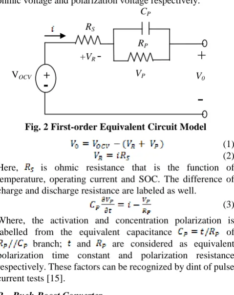
Battery model is exercised to conduct the affiliation between internal and external performance of a battery. Usually two types of battery models are classified namely electrochemical model and equivalent circuit model [12]. Electrochemical model entirely depends on internal chemical reaction of a battery. For this reason, electrochemical model contains analytical complexity and calculation delinquencies to achieve parameter accurateness. On the other hand, equivalent circuit model relies on external dynamic appearances that can sidestep the comprehensive deviousness of internal electrochemical progressions. Therefore, Equivalent circuit model is frequently enrolled to replicate the cells’ peripheral characteristics and enhance the truthfulness of BMS [13],[14]. This paper contains the first-order Thevenin Equivalent circuit model which is shown in Fig. 2; V0 and VOCV are the terminal voltage and open circuit voltage (OCV) respectively as well as the relation between them can
[image:2.595.308.548.68.370.2]be stated from (1) to (3). Here, VR and VP are termed as the ohmic voltage and polarization voltage respectively.
Fig. 2 First-order Equivalent Circuit Model (1) (2) Here, is ohmic resistance that is the function of temperature, operating current and SOC. The difference of charge and discharge resistance are labeled as well.
(3)
Where, the activation and concentration polarization is labelled from the equivalent capacitance of branch; and are considered as equivalent polarization time constant and polarization resistance respectively. These factors can be recognized by dint of pulse current tests [15].
B. Buck-Boost Converter
Non-inverting DC/DC Buck-Boost converter can convert the supply-voltage lower or higher according to its’ requirements. Fig.3 shows the circuit diagram of a synchronous Buck-Boost converter [16][17]. Four high speedy MOSFET switches (Q1~Q4) are engaged to regulate the energy conduction of cell strings. Following to the energy requirement of the system, the converter can be applied for Buck, Boost or Buck-Boost converter. When the cell voltage is higher or lower comparing to the desired voltage, the converter is set to buck and boost mode operation respectively. From Fig.3, in case of Buck mode operation, Q3 is off and Q4 is on at all times as well as Q1 and Q2 are exploited to control the procedure. When MOSFET Q1 is closed and Q2 is open, inductor is charged by the supply power. During inductor charging period, capacitor provides output current and the inductor current rises in straight. Additionally, Q2 is closed and Q1 is open at inductor discharging period as well as inductor delivers stocked-energy to the capacitor to charge the load. Average terminal voltage Vout(equals dVSC) can be
obtained by controlling duty cycle d<1 along with the supply voltage VSC. Furthermore, MOSFET M1 is on and M2 is off
permanently for boost mode operation. M3 is closed and M4 is open at inductor charging period as well as M3 and M4 operations are reversed at discharging cycle. The average output voltage Vout equals 1/(1-d)VSC. The converter is fixed to
Buck-Boost maneuver when the cell voltage is adjacent to the desired voltage. In this mode MOSFET M1 and M3 are kept closing as well as M2 and M4 are kept opening for inductor charging. Again the MOSFETs are operated in reverse position to discharge the inductor. The output load voltage Voutequals to d/(1-d)VSC.
VP CP RP
+
-
VOCV-
+
V0 RS-International Journal of Innovative Technology and Exploring Engineering (IJITEE) ISSN: 2278-3075, Volume-8 Issue-9, July 2019
Fig.3 Four switched DC/DC Buck-Boost converter
C. SOC Estimation
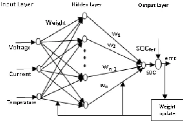
State of charge (SOC) is a precarious valuation for battery enduring capacity. The significance of SOC estimation accuracy is prodigious for lithium-ion battery to certify its safety operation and avoid from over-charging and deep-discharging factors. Nevertheless, SOC estimation for the battery is a challenging issue owing to the nonlinear electrochemical reactions [18][19]. In this study, BPNN based SOC estimation algorithm is employed for which the structural design of the procedure is shown in Fig. 4. BPNN is the most far and widely utilized onlooker technique for nonlinear systems as a result of its self-learning and feedback characteristic [20]. The proposed model estimates SOC for every single cell individually as indicated in Fig.5. Three parameters: voltage, current and temperature are collected from each cell in addition to estimate SOC bestowing the equations from (4) to (7). Weights are attuned according to the Root Mean Square Error (RMSE) of the SOC estimation so as to construe the assessed-outcomes more accurately. The total input of a hidden layer neuron can be deliberated from (4)
(4) Where, is total input of the hidden layer neuron n, is the value of input neuron to hidden layer neuron n, is weight between input layer neuron i and hidden layer neuron n, is the bias of the hidden layer neuron n.
Furthermore, in the hidden layer neuron, the applied activation function is the tangent function (5). In addition, the evaluation of output layer neuron can be obtained from (6)
(5)
(6) Here, is total outcome of the output layer neuron , is the value of hidden layer neuron to output layer neuron , is the weight between hidden layer neuron and output layer neuron , is the bias of the output layer neuron .
[image:3.595.54.295.65.152.2]
Fig.5 SOC estimation for every single cell In the output layer neuron, the applied activation function is the sigmoid function. Output can be calculated from (7)
(7)
D. Cell Equalization
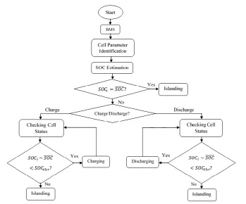
In the battery pack, operational voltage/current is attained by concerning numerous cells in series/parallel connection. Higher terminal voltage is obtained by connecting the cells in series connection. In contrast, parallel connection attains high capacity of a battery pack by the addition of over-all ampere-hour [21]–[23]. To avoid the cells damaging and lengthen the battery life-time, charging/discharging of the entire battery pack is stopped instantaniously if any cell reaches to the particular charging or discharging cut-off voltage respectively neglecting others. With the purpose of progressing the adeptness of battery pack along with possessing the standardization of SOC in the cell string, active charge equalization technique is implemented through the Buck-boost DC/DC converter. BMS commands the converters to decrease SOC variance among the cells. In order to balance the charge equalization of the cell string, average SOC is compared with all cell’s SOC as well as higher SOC containing cells transfer energy to lower charged cells. If the dissimilarity between average SOC and a cell SOC occurs more than a presumed threshold value, BMS facilitates the corresponding DC/DC Buck-boost converter to charge or discharge the cell as stated by the requirement. Fig. 6 designates the cell balancing operational appliance for the proposed model. The mathematical explanation of the active charge equilibrium scheme is stated in (8)
(8)
Here, is the SOC of a particular cell, is average SOC of the cell string and is the threshold SOC of the system that is predefined before simulation.
[image:3.595.68.257.634.759.2]Active Cell Balancing Control Method for Series-Connected Lithium-Ion Battery
2427
Published By:
Blue Eyes Intelligence Engineering Retrieval Number: I8905078919/19©BEIESP
[image:4.595.64.275.58.158.2]DOI:10.35940/ijitee.I8905.078919
Fig. 6 Active charge equalization structural design. IV. SIMULATION RESULT & DISCUSSION With the aim of validating the usefulness of the anticipated BMS, the proposed model is simulated in the Matlab/Simulink environment. The battery model including the active cell-balancing methodology are assembled in the Simulink background. Generally non-uniform characteristics are occurred among the series-connected cells. Consequently, Three serially-allied A123 Li-iron-phosphate ANR26650M1 cells (Nominal voltage 3.3V and capacity 2.3Ah) are employed in this project for which the relationship between OCV and SOC of the predictable LiFePO4 cell is shown in Fig. 7(a). Root Mean Square Error (RMSE) of the estimated SOC as well as Table 1 permits the authentication of the proposed methodology because of the innovative BPNN algorithm. Some authors studied on SOC estimation policy accompanied by Proportional Integral (PI) Observer, Extended Kalman Filter (EKF), Dual EKF (DEKF), H-infinity EKF (HEKF) etc. Nevertheless, the error produced
by BPNN algorithm is reduced comparing to other standing methods as a result of weight regulation scheme. Though the cells contain same initial capacity (78% SOC) for the real world application in case of without cell balancing methodology, SOC differs at charging/discharging condition after some moment. However in BMS, the SOC inequality of the cells is diminished by dint of active charge equalization strategy. Fig.8 illustrates the estimated SOC charging/discharging profile of 3 cells for before and after cell balancing stratagem. Although the divergence of SOC is occurred at charging condition for the scarcity of SOC balancing technique, the dissimilarity is deducted with the help of novel charge balancing process. Similarly, Fig.9 to Fig.10 clarifies the advantages of the proposed BMS in lieu of cells terminal voltage and current profile by comparing the before and after active cell balancing strategy. In addition, the entire flowchart of the planned methodology is shown in Fig.11.
Table I. Reviews of SOC estimation approaches.
Reference Year Battery
Model
Algorithm Error (%)
[24] 2016 1st order PI Observer 3
[25] 2017 1st order Dual EKF <5
[26] 2017 1st order EKF 3
[27] 2018 2nd order HEKF <2
[2] 2019 3rd order EKF 2
Proposed Model
2019 1st order BPNN <1.2
Controlling signal from BMS
DC/DC DC/DC DC/DC
+
-
(b) (a)
Fig.8 SOC charging/discharging profile of 3 cells (a) Before (b) After cell balancing (b)
Fig. 7 (a) OCV vs SOC Relationship for LiFePO4 cell (b) RMSE for the estimated SOC
[image:4.595.49.509.425.752.2]Active Cell Balancing Control Method for Series-Connected Lithium-Ion Battery
(b)
(b) (a)
Fig.9 Voltage profile of 3 cells (a) Before and (b) After cell balancing
[image:5.595.85.503.113.254.2](a) (b)
Fig.10 Current profile of 3 cells (a) Before (b) After cell balancing
[image:5.595.74.424.468.758.2]International Journal of Innovative Technology and Exploring Engineering (IJITEE) ISSN: 2278-3075, Volume-8 Issue-9, July 2019
2429
Published By:
Blue Eyes Intelligence Engineering Retrieval Number: I8905078919/19©BEIESP
DOI:10.35940/ijitee.I8905.078919
V. CONCLUSION
With the intention of progressing the overall productivity of a battery pack, an active energy equalization scheme is proposed for LiFePO4 battery combining with online SOC estimation technique. BMS commands the activation signal through Buck-boost converter to supervise the battery pack with the help of SOC estimation levels. Each cell is instructed to charge or discharge properly following the guidance of BMS. Moreover, the weakest cell is recommended for repairing or even replacing from the battery pack if the charge level of this cell is not calibrating with active charge equalization technique in an attempt to escape from the stress on the strongest cells. In the long run, comparing to the existing methods, the proposed BMS contains succeeding advantages:
The deliberated BMS can accurately orchestrate the SOCs of the series-connected cells accompanied by minimalizing the estimation error.
In the battery pack, there is no discomfiture of energy on account of active charge balancing strategy through bidirectional Buck-boost DC/DC converter that decreases energy dissonance from one cell to another.
The proposed methodology can be effortlessly prosecuted to several kinds of battery packs caused by its uncomplicatedness.
Conflicts of Interest
The authors declare no conflict of interest.
Acknowledgments
Authors would like to acknowledge the facilities supported by Universiti Malaysia Sarawak (UNIMAS).
References
1. S. Ci, N. Lin, and D. Wu, “Reconfigurable Battery Techniques and Systems: A Survey,” IEEE Access, vol. 4, pp. 1175–1189, 2016. 2. H. Ren, Y. Zhao, S. Chen, and T. Wang, “Design and implementation of
a battery management system with active charge balance based on the SOC and SOH online estimation,” Energy, pp. 908–917, 2019. 3. W. Diao, N. Xue, V. Bhattacharjee, J. Jiang, O. Karabasoglu, and M.
Pecht, “Active battery cell equalization based on residual available energy maximization,” Appl. Energy, vol. 210, no. July, pp. 690–698, 2018.
4. Y. Ye and K. W. E. Cheng, “Analysis and Design of Zero-Current Switching Switched-Capacitor Cell Balancing Circuit for Series-Connected Battery/Supercapacitor,” IEEE Trans. Veh. Technol., vol. 67, no. 2, pp. 948–955, 2018.
5. Y. Chen, X. Liu, Y. Cui, J. Zou, and S. Yang, “A MultiWinding Transformer Cell-to-Cell Active Equalization Method for Lithium-Ion Batteries with Reduced Number of Driving Circuits,” IEEE Trans. Power Electron., vol. 31, no. 7, pp. 4916–4929, 2016.
6. V. Knap et al., “Self-balancing feature of Lithium-Sulfur batteries,” J. Power Sources, vol. 372, no. October, pp. 245–251, 2017.
7. M. Caspar, T. Eiler, and S. Hohmann, “Systematic Comparison of Active Balancing: A Model-Based Quantitative Analysis,” IEEE Trans. Veh. Technol., vol. 67, no. 2, pp. 920–934, 2018.
8. X. Cui, W. Shen, Y. Zhang, C. Hu, and J. Zheng, “Novel active LiFePO4 battery balancing method based on chargeable and dischargeable capacity,” Comput. Chem. Eng., vol. 97, pp. 27–35, 2017.
9. M. A. Hannan, M. M. Hoque, A. Hussain, Y. Yusof, and P. J. Ker, “State-of-the-Art and Energy Management System of Lithium-Ion Batteries in Electric Vehicle Applications: Issues and Recommendations,” IEEE Access, vol. 6, pp. 19362–19378, 2018 10. N. Bouchhima, M. Schnierle, S. Schulte, and K. P. Birke, “Active
model-based balancing strategy for self-reconfigurable batteries,” J. Power Sources, vol. 322, pp. 129–137, 2016.
11. E. Chatzinikolaou and D. J. Rogers, “Cell SoC Balancing Using a Cascaded Full-Bridge Multilevel Converter in Battery Energy Storage Systems,” IEEE Trans. Ind. Electron., vol. 63, no. 9, pp. 5394–5402, 2016.
12. J. Yang, B. Xia, Y. Shang, W. Huang, and C. C. Mi, “Adaptive state-of-charge estimation based on a split battery model for electric vehicle applications,” IEEE Trans. Veh. Technol., vol. 66, no. 12, pp. 10889–10898, 2017.
13. C. S. Chin, Z. Gao, J. H. K. Chiew, and C. Zhang, “Nonlinear temperature-dependent state model of cylindrical LiFePO 4 battery for open-circuit voltage, terminal voltage and state-of-charge estimation with extended kalman filter,” Energies, vol. 11, no. 9, 2018.
14. Q. Wang, J. Wang, P. Zhao, J. Kang, F. Yan, and C. Du, “Correlation between the model accuracy and model-based SOC estimation,” Electrochim. Acta, vol. 228, pp. 146–159, 2017.
15. R. Zhang et al., “A study on the open circuit voltage and state of charge characterization of high capacity lithium-ion battery under different temperature,” Energies, vol. 11, no. 9, 2018.
16. J. K. Shiau and C. W. Ma, “Li-Ion battery charging with a buck-boost power converter for a solar powered battery management system,” Energies, vol. 6, no. 3, pp. 1669–1699, 2013.
17. T. H. Wu, C. S. Moo, and C. H. Hou, “A battery power bank with series-connected buck-boost-type battery power modules,” Energies, vol. 10, no. 5, pp. 1–12, 2017.
18. R. U. I. Xiong, S. Member, J. Cao, Q. Yu, and S. Member, “Critical Review on the Battery State of Charge Estimation Methods for Electric Vehicles,” vol. 6, 2018.
19. A. Bani Ahmad, C. A. Ooi, D. Ishak, and J. Teh, “State-of-Charge Balancing Control for ON/OFF-Line Internal Cells Using Hybrid Modular Multi-Level Converter and Parallel Modular Dual L-Bridge in a Grid-Scale Battery Energy Storage System,” IEEE Access, vol. 7, pp. 131–147, 2019.
20. M. A. Hannan, M. S. H. Lipu, A. Hussain, M. H. Saad, and A. Ayob, “Neural network approach for estimating state of charge of lithium-ion battery using backtracking search algorithm,” IEEE Access, vol. 6, pp. 10069–10079, 2018.
21. Y. Ye, K. W. E. Cheng, Y. C. Fong, X. Xue, and J. Lin, “Topology, Modeling, and Design of Switched-Capacitor-Based Cell Balancing Systems and Their Balancing Exploration,” IEEE Trans. Power Electron., vol. 32, no. 6, pp. 4444–4454, 2017.
22. Q. Ouyang, J. Chen, J. Zheng, and H. Fang, “Optimal cell-to-cell balancing topology design for serially connected lithium-ion battery packs,” IEEE Trans. Sustain. Energy, vol. 9, no. 1, pp. 350–360, 2018. 23. M. Dubarry, A. Devie, and B. Y. Liaw, “Cell-balancing currents in
parallel strings of a battery system,” J. Power Sources, vol. 321, pp. 36–46, 2016.
24. C. Zhang, J. Jiang, L. Zhang, S. Liu, L. Wang, and P. C. Loh, “A generalized SOC-OCV model for lithium-ion batteries and the SOC estimation for LNMCO battery,” Energies, vol. 9, no. 11, 2016. 25. N. T. Tran, A. B. Khan, and W. Choi, “State of charge and state of health
estimation of AGM VRLA batteries by employing a dual extended Kalman filter and an ARX model for online parameter estimation,” Energies, vol. 10, no. 1, 2017.
26. I. Baccouche, S. Jemmali, B. Manai, N. Omar, and N. Essoukri Ben Amara, “Improved OCV model of a Li-ion NMC battery for online SOC estimation using the extended Kalman filter,” Energies, vol. 10, no. 6, pp. 1–22, 2017.
27. L. Zhao, Z. Liu, and G. Ji, “Lithium-ion battery state of charge estimation with model parameters adaptation using H∞extended Kalman filter,” Control Eng. Pract., vol. 81, no. June, pp. 114–128, 2018.
AUTHORS PROFILE
Ohirul Qays was born in Chuadanga, Bangladesh, in 1995. He received his B.Eng. degree from Khulna University of Engineering & Technology, Bangladesh, in 2017. He worked for a research assistantship grant in 2018 for power electronics section entitled by ‘’A Novel Multi input DC-DC Power Converter for Integrated Solar PV-Micro Hydro Hybrid Renewable Energy System’’. Currently he is continuing the M.Sc. degree in electrical and electronics engineering in Universiti Malaysia Sarawak. He is
Active Cell Balancing Control Method for Series-Connected Lithium-Ion Battery
KUET Brach. His research interests include Renewable Energy, Power Electronics, Power System and Control System.
Dr. Yonis.M.Yonis Buswig was born in Benghazi, Libya, in 1984. He received his B.Eng. degree from Omar Al-Mukhtar University, Libya, in 2008. The M.Sc. degree in electrical and electronics engineering from Tun Hussein Onn University of Malaysia (UTHM), Batu Pahat, Johor, Malaysia, in 2011. In 2015, he was awarded his Ph.D. degree from Department of Power Engineering, Faculty of Electrical Engineering, Tun Hussein Onn University of Malaysia (UTHM). Currently, He is a Lecturer in the Electrical and Electronic Engineering Department, Faculty of Engineering, Universiti Malaysia Sarawak. Yonis.M.Yonis Buswig has authored and co-authored a number of well-recognized journals and conference papers and has been a regular reviewer for IEEE, Wiley and other journals. His current research interests include the area of Power Electronics, Renewable energy technology, and Motor Drives Control. He is a Member in Board of Engineers Malaysia (BEM).