IMPACT TEST SIMULATION WITH DIFFERENT IMPACT
DIRECTION USING FEA FOR BUMPER CAR
This report is submitted in accordance with requirement of the Universiti Teknikal Malaysia Melaka (UTeM) for the Bachelor Degree of Mechanical Engineering
(Structure and Material) (Hons.)
By
MUHAMMAD NABEL BIN ZAKARIA B041410041
930828-04-5315
ii
DECLARATION
I hereby, declared this report entitled “Impact Test Simulation with Different Impact Direction Using FEA for Bumper Car” is the results of my own research except as cited in
references.
Signature : ………...
Author’s Name : MUHAMMAD NABEL BIN ZAKARIA
iii
APPROVAL
This report is submitted to the Faculty of Mechanical Engineering of Universiti Teknikal Malaysia Melaka (UTeM) as a partial fulfilment of the requirements for the degree of Bachelor of Mechanical Engineering (Structure and Material) (Hons.). The member of the
supervisory is as follow:
iv
DEDICATION
v
ABSTRACT
vi ABSTRAK
vii
ACKNOWLEDGEMENT
Foremost, I would like to express my greatest gratitude to Almighty God for giving me strength and courage to finally complete my bachelor degree project with the best I could. Indeed, without His Help and Well, nothing can be accomplished.
My deep and sincere gratitude goes to my most respected supervisor, Dr. Mohd Basri bin Ali, for his comprehensible instruction, stimulating encouragement and valuable suggestions in completing this project.
I also would like to take this opportunity to extend my sincere thanks to all person that helped me throughout this project. Besides, thanks to all my group members and whoever that helped me directly or indirectly for their support and contribution of idea while doing this project. The uphill struggle is hard and could not have been achieved without the inspiration and motivation from the people around me.
Not to forget, my special one, Puteri Eliani Fikri who had been there through the ups and downs of this whole project. Her continuous support, generous ideas and coherent guidance helped me tremendously to complete this project.
viii CONTENT
CHAPTER CONTENT PAGE
DECLARATION ii
APPROVAL iii
DEDICATION iv
ABSTRACT v
ABSTRAK vi
ACKNOWLEDGEMENT vii
TABLE OF CONTENT viii
LIST OF TABLES xi
LIST OF FIGURES xii
LIST OF ABBREVIATIONS xvi
LIST OF SYMBOLS xvii
CHAPTER 1 INTRODUCTION 1
1.1 Background 1
1.2 Problem Statement 3
1.3 Objective 4
1.4 Scope of Project 4
CHAPTER 2 LITERATURE REVIEW 5
2.1 Introduction 5
2.2 Function of Bumper 5
2.3 Bumper Systems 7
2.4 Components of Bumper System 8
2.4.1 Fascia 8
2.4.2 Energy absorber 8
ix
2.4.4 Reinforcing beam or bumper beam 9
2.5 Frontal Crash Test Standard 9
2.5.1 New Car Assessment Programme (NCAP)
10
2.5.2 Federal Motor Vehicle Safety Standard (FMVSS) No. 208
11
2.5.2.1 The Full Frontal Fixed Rigid Barrier Test
11
2.5.2.2 The Oblique Frontal Fixed Rigid Barrier Test
11
2.6 Impact Mechanics 12
2.7 Oblique Impact 14
CHAPTER 3 METHODOLOGY 17
3.1 Introduction 17
3.2 Flowchart 18
3.3 Determining the Front Bumper Design 19
3.4 Identifying the Parameters 19
3.4.1 Material selection 19
3.4.2 Velocity of impactor 19
3.5 3D Modelling 20
3.5.1 Bumper 20
3.5.2 Impactor 21
3.6 ABAQUS Sequences 22
3.6.1 Assembly 22
3.6.2 Material properties 24
3.6.3 Step 26
3.6.4 Interaction 27
3.6.5 Load 29
3.6.6 Meshing 30
3.6.7 Job 31
x
CHAPTER 4 RESULTS, ANALYSISN AND DISCUSSION 33
4.1 Introduction 33
4.2 Deformation in Simulation for 0˚ Impact 33 4.3 Deformation in Simulation for 30˚ Impact 38 4.4 Deformation in Simulation for 45˚ Impact 43 4.5 Impact Angles of 30˚, 45˚, -30˚, and -45˚. 48
4.5.1 Deformation in simulation for -30˚ Impact.
48
4.5.2 Deformation in simulation for -45˚ Impact.
53
4.5.3 Comparison between impact angles of 30˚, 45˚, -30˚, and -45˚.
58
4.5.3.1 30˚ 30˚ and -30˚ impact angle. 58 4.5.3.2 45˚ 45˚ and -45˚ impact angle. 61 4.6 Energy Absorption of Bumper on 0˚, 30˚ and
45˚ Impact Angles.
63
4.7 Chapter Summary 69
CHAPTER 5 CONCLUSION AND RECOMMENDATION 70
5.1 Introduction 70
5.2 Conclusion 70
5.3 Recommendation 72
xi
LIST OF TABLES
TABLE TITLE PAGE
3.1 Material properties for aluminium and steel. 24
xii
LIST OF FIGURES
FIGURE TITLE PAGE
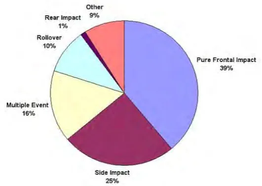
1.1 Volvo’s distribution of serious-to-fatal crashes. 2
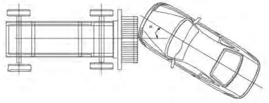
1.2 Oblique Moving Deformable (MDB) Test. 3
2.1 Bumper systems components. 6
2.2 Diagram for types of bumper system. 7
2.3 Standard facility for NCAP Rigid Barrier Test. 10
2.4 Full Frontal Fixed Rigid Barrier Test. 11
2.5 Oblique Frontal Fixed Rigid Barrier Test 12
2.6 Normal and tangential line of oblique impact. 15
3.1 Project flow chart. 18
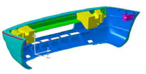
3.2 Imported front car bumper in ABAQUS 21
3.3 Settings to create part for impactor. 22
3.4 Creating assembly from impactor and bumper. 23
3.5 Points (yellow) used for instance (red) translation. 24 3.6 Inserting the material properties for aluminium and steel. 25
3.7 Creating section for each material. 25
3.8 Green bumper and impactor indicate that the materials are correctly assigned.
xiii
3.9 Settings for the Step-1. 27
3.10 Settings for interaction. 28
3.11 Settings for the interaction property. 28
3.12 Settings for boundary condition on bumper. 29
3.13 Inserting the velocity for impactor. 30
3.14 Tetrahedral meshing for bumper 31
3.15 Hexahedral meshing for impactor. 31
3.16 Submitting data on job module. 32
4.1 Von Mises stress for 0˚ impact. 34
4.2 Reaction force on the top pins. 34
4.3 Displacement on the bumper. 35
4.4 Four nodes taken for 0˚ impact. 35
4.5 Graph of force-displacement at four nodes for 0˚ impact. 36 4.6 Graph of average force-displacement for 0˚ impact. 37
4.7 Internal energy graph for 0˚ impact. 37
4.8 Kinetic energy graph for 0˚ impact. 38
4.9 Von Mises stress for 30˚ impact. 38
4.10 Reaction force on the top right-side pins. 39
4.11 Displacement on the bumper. 39
4.12 Four nodes taken for 30˚ impact. 40
4.13 Graph of force-displacement at four nodes for 30˚ impact. 40 4.14 Graph of average force-displacement for 30˚ impact. 41
4.15 Internal energy graph for 30˚ impact. 42
xiv
4.17 Von Mises stress for 45˚ impact. 43
4.18 Reaction force on the bottom right-side pin. 44
4.19 Displacement on the bumper. 44
4.20 Four nodes taken for 45˚ impact. 45
4.21 Graph of force-displacement at four nodes for 45˚ impact. 45 4.22 Graph of average force-displacement for 45˚ impact. 46
4.23 Internal energy graph for 45˚ impact. 47
4.24 Kinetic energy graph for 45˚ impact. 47
4.25 Von Mises stress for -30˚ impact. 48
4.26 Reaction force on the top left-side pins. 49
4.27 Displacement on the bumper. 49
4.28 Four nodes taken for -30˚ impact. 50
4.29 Graph of force-displacement at four nodes for -30˚ impact. 50 4.30 Graph of average force-displacement for -30˚ impact. 51
4.31 Internal energy graph for -30˚ impact. 52
4.32 Kinetic energy graph for -30˚ impact. 52
4.33 Von Mises stress for -45˚ impact. 53
4.34 Reaction force on the bottom left-side pin. 54
4.35 Displacement on the bumper. 54
4.36 Four nodes taken for -45˚ impact. 55
4.37 Graph of force-displacement at four nodes for -45˚ impact. 55 4.38 Graph of average force-displacement for -45˚ impact. 56
4.39 Internal energy graph for -45˚ impact. 57
xv
4.41 Average force-displacement graph for 30˚ and -30˚ impact. 59 4.42 Internal energy graph for 30˚ and -30˚ impact. 60
4.43 Kinetic energy graph for 30˚ and -30˚ impact. 60
4.44 Average force-displacement graph for 45˚ and -45˚ impact. 62 4.45 Internal energy graph for 45˚ and -45˚ impact. 62
4.46 Kinetic energy graph for 45˚ and -45˚ impact. 63
4.47 Load-displacement rsponse for velocity of 50 km/hr for three
difeferent thickness of twisted tube. 65
4.48 Effect of angle of attack on energy absorption by composite
laminates of different thickness. 65
4.49 Energy absorption percentage of each sub-structure of hybrid-cored sandwich plate plotted as a function of oblique angle, with initial impact velocity fixed at 2.4 km/s.
66
4.50 Average force-displacement graph for 0˚, 30˚ and 45˚ impact
angle. 67
4.51 Internal energy graph for 0˚, 30˚ and 45˚ impact angle. 68 4.52 Kinetic energy graph for 0˚, 30˚ and 45˚ impact angle. 69
4.53 Cross section from front to back of bumper. 69
5.1 Y-axis and x-axis in all simulations. 71
5.2 Cross section from front to back of bumper. 71
xvi
LIST OF ABBEREVATIONS
xvii
LIST OF SYMBOLS
˚ = angle
s = seconds
J = Joules
mm = millimeter
N = Newton
EA = energy absorption
F = force
U = displacement % = percentage km = kilometre
h = hour
m = mass
v = velocity
e = coefficient of restitution δmax = maximum deflection
CHAPTER 1
INTRODUCTION
1.1 Background
2
Figure 1.1: Volvo’s distribution of serious-to-fatal crashes (Donga, 2011).
There are many tries to lessen the effect from the frontal impact crashes using air bags and energy absorption bumper.(Cheon et al., 1995). Bumper is one of necessary part in passenger vehicle as it is the main tool to damp the energy from crashes and also protect others of vehicle such as lamps, hood and cooling system especially the front bumper (Dange, Buktar, & Raykar, 2015; Davoodi et al., 2011). The bumper system consists three main parts: fascia, energy absorber, and bumper beam as shown in Figure 1.2 (Davoodi et al., 2011, 2012).
3
Figure 1.2: Oblique Moving Deformable (MDB) Test (Hollowell et al., 1999).
Studies also showed that critical penetration energy increase as the curvature increase, impact angle increase and interface increase (Yang, Cho, Im, Cha, & Kim, 2006) and oblique angle is a crucial factor not only on the penetration resistance of the target plate but also on its deformation/failure modes (Ni, Jin, & Lu, 2014).
1.2 Problem Statement
Studies shows that many crashes happened form the frontal impact and this lead to many injuries and vehicles damage (Cheon et al., 1995; Donga, 2011). During all these frontal crashes, the first part that receives impact is the front bumper (Davoodi et al., 2012).This shows that for the front bumper, the energy absorption is really important because it is a main tool to damp the energy from crashes.
4
1.3 Objectives
Impact test simulation with different impact direction using FEA for bumper car. 1. To determine the energy absorbed with different angle of impact direction. 2. To correlate the energy absorbed with different impact direction.
3. To compare the results with previous studies.
1.4 Scope
5
CHAPTER 2
LITERATURE REVIEW
2.1 Introduction
Bumper is one of necessary part in passenger vehicle as it is the main tool to damp the energy from crashes and also protect others of vehicle such as lamps, hood and cooling system especially the front bumper (Dange et al., 2015; Davoodi et al., 2011). In previous chapter, the studies about severity of type of crashes and bumper development history are brought up to show the importance of car bumper. However, in this chapter more studies will be referred to explain the details of car bumper system, crash test standard, impact mechanics and the effect of impact direction towards impact response. These are important things to be reviewed so that the energy absorption on front car bumper during frontal or even oblique impact.
2.2 Function of Bumper
6
Figure 2.1: Bumper systems components (Davoodi et al., 2011)
Passive safety car system is the physical system that shield the passengers during collision such as front and rear car bumpers that can absorb impact energy (Calienciug, 2012). The main purpose of bumper is the absorption of impact energy to reduce the damage which can affect the car, passengers and even pedestrian. (Bohra & Pawar, 2014; Calienciug, 2012; Davoodi, Sapuan, & Yunus, 2008; Marzbanrad, Alijanpour, & Kiasat, 2009; Moona et al., 2015). Bumper reduces the damages of collision with other cars and objects due to their large deformation zones by deforming itself and absorb the force (kinetic energy) during a collision (Kleisner & Zemˇ, 2009)
7 2.3 Bumper Systems
[image:24.595.86.528.288.655.2]The whole frontal bumper system consists the following main parts, a fascia, energy absorber and bumper beam (Davoodi et al., 2011; Kleisner & Zemˇ, 2009). There are important factors that an engineer or designer must put in thought when selecting a bumper system. The most crucial factor is the ability of the bumper system to absorb enough energy (Steel Market Development Institute, 2013). Figure 2.1 shows the diagram for types of bumper systems.
Figure 2.2: Diagram for types of bumper system (Steel Market Development Institute, 2013)
Metal facebar
Plastic fascia, reinforcing beam and foam or honeycomb energy
absorber
Plastic fascia, reinforcing beam and mechanical energy
absorbers
Plastic fascia and reinforcing beam
Plastic fascia, reinforcing beam, foam, and mechanical energy