This is a repository copy of Safety-Critical Java: : level 2 in practice.
White Rose Research Online URL for this paper:
http://eprints.whiterose.ac.uk/106765/
Version: Accepted Version
Article:
Luckcuck, Matt, Wellings, Andy orcid.org/0000-0002-3338-0623 and Cavalcanti, Ana
orcid.org/0000-0002-0831-1976 (2016) Safety-Critical Java: : level 2 in practice.
Concurrency and Computation: Practice and Experience. pp. 1-27. ISSN 1532-0634
https://doi.org/10.1002/cpe.3951
[email protected] https://eprints.whiterose.ac.uk/
Reuse
Items deposited in White Rose Research Online are protected by copyright, with all rights reserved unless indicated otherwise. They may be downloaded and/or printed for private study, or other acts as permitted by national copyright laws. The publisher or other rights holders may allow further reproduction and re-use of the full text version. This is indicated by the licence information on the White Rose Research Online record for the item.
Takedown
If you consider content in White Rose Research Online to be in breach of UK law, please notify us by
Safety-Critical Java: Level 2 in Practice
Matt Luckcuck, Andy Wellings and Ana Cavalcanti
16th September 2016
Abstract
Safety Critical Java (SCJ) is a profile of the Real-Time Specification for Java that brings to the safety-critical industry the possibility of using Java. SCJ defines three compliance levels: Level 0, Level 1 and Level 2. The SCJ specification is clear on what constitutes a Level 2 application in terms of its use of the defined API, but not the occasions on which it should be used. This paper broadly classifies the features that are only available at Level 2 into three groups: nested mission sequencers, managed threads, and global scheduling across multiple processors. We explore the first two groups to elicit programming requirements that they support. We identify several areas where the SCJ specification needs modifications to support these requirements fully; these include: support for terminating managed threads, the ability to set a deadline on the transition between missions, and augmentation of the mission sequencer concept to support composibility of timing constraints. We also propose simplifications to the termination protocol of missions and their mission sequencers. To illustrate the benefit of our changes, we present excerpts
from a formal model of SCJ Level 2 written in Circus, a state-rich process algebra
for refinement.
1
Introduction
An international effort has produced a specification for a high-integrity real-time version of Java: Safety-Critical Java (SCJ) [24]. SCJ is based on a subset of Java augmented by the Real-Time Specification for Java (RTSJ) [38], which supplements Java’s garbage-collected heap memory model with support for memory regions [37] called memory areas.
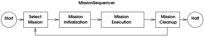
The SCJ programming model is based on the notion of a mission. Each mission con-sists of a set of periodic (PEH), aperiodic (APEH), and one-shot (OSEH) event handlers, and no-heap managed real-time threads. The execution of a mission progresses through an initialisation, execution, and cleanup phase (see Figure 1). A mission’s handlers and threads are created and registered during its initialisation phase. A mission continues to execute until one of its handlers, threads, or a peer mission requests termination, causing control to flow into a mission cleanup phase. An application-defined mission sequencer determines the sequence of missions to be executed.
Start Mission Halt Cleanup
Mission Execution Select
Mission Initialization Mission
[image:3.595.128.463.71.132.2]MissionSequencer
Figure 1: Safety Critical Mission Phases (taken from [24])
area of a mission is cleared out at the end of each mission. Each release of a handler has an associated per-release scoped memory area, cleared out at the end of the release.
In the case of a thread, the execution of its associated run() method is viewed as a
single release, and consequently, it is associated with its own local scoped memory area. Additionally, during a release, a stack of temporary private scoped memory areas can be used.
The SCJ language specification defines three compliance levels (Levels 0, 1 and 2), which reflect three supported programming and execution models. The compliance levels reflect increased levels of complexity in terms of the available programming features and, therefore, of the supported programs, with direct impact on the effort required for certification. It is accepted that the effort required to certify a program that exploits the generality of Level 2 capabilities may be significantly greater than that required to certify programs that use only the more limited capabilities of the lower compliance levels.
The differences between the three compliance levels are summarised in Table 1. The schedulable objects available at each level include those listed for that level and those listed for the previous levels. While mission sequencers are schedulable objects and are used at all compliance levels, they can only be registered to a mission at Level 2, as we explain below. The Suspension column refers to the availability of features like
Object.wait(),Object.notify(), andServices.delay().
Execution Model
Schedulable Objects
Suspension Platform
Level 0 Cyclic Executive Periodic Event Handler No Single Processor
Level 1 Preemptive
Prior-ity
Scheduling
Aperiodic and One-Shot
Event Handlers
No Multi-Processor
Level 2 Preemptive
Prior-ity
Scheduling
Mission
Se-quencers and
Managed Threads
Yes
Multi-Processor Global Scheduling
Table 1: Comparison of SCJ Compliance Level Features
A Level 0 application’s execution model is essentially a cyclic executive. In this model, only periodic handlers are supported; they are executed sequentially in a precise, clock-driven time line [23]. A single mission sequencer controls the sequential execution of one or more missions.
At SCJ Level 1, missions are controlled by a single mission sequencer. The available schedulable objects are periodic, aperiodic, and one-shot event handlers. At Level 1, schedulable objects are executed concurrently by a preemptive priority-based scheduler;
any access to shared data has to be performed bysynchronized methods to avoid race
[image:3.595.88.528.458.594.2]to shared variables by one thread to propagate to all other threads that share access to those same variables. A notable restriction of the Level 1 programming model is
that use of Object.wait()and Object.notify()is prohibited. Arbitrary use of such
methods complicates the ability to perform schedulability analysis.
At Level 2, missions are executed sequentially by a top-level mission sequencer, as with Level 1. In addition, each mission may register nested mission sequencers during its initialisation phase. Once these nested mission sequencers begin running, they each execute a sequence of child missions, independently of the top-level mission sequencer. Computation in a Level 2 mission can be performed by periodic, aperiodic, and one-shot handlers, and no-heap managed real-time threads. Each child mission has its own mission memory, distinct from its parent’s mission memory. A Level 2 application may use Java suspension features.
It is clear that those applications that can be scheduled using cyclic-executive tech-niques should be implemented at Level 0. Furthermore, applications that can use simple analysable fixed-priority scheduling should use Level 1. Hence, the required scheduling techniques are a primary indicator of whether or not Level 0 should be used. However, Level 2 also targets fixed-priority scheduling, so this cannot be used to decide between using Level 1 or Level 2.
To understand the purpose of Level 2, it is necessary to discover the generic application-level programming requirements for which Level 2 functionality is necessary. In the current version of the specification, this is not provided in the rationale for the three compliance levels.
We broadly classify the additional functionality provided at Level 2 into three groups:
1. nested mission sequencers;
2. managed threads: including the use of the Object.wait(),Object.notify(),
HighResolutionTime.waitForObject()and Services.delay() methods; and,
3. global scheduling across multiple processors.
We explore the first group in Section 2, showing how they provide support for two example applications: a Space Shuttle, which has several modes of operation, with mode-specific schedulable objects and persistent schedulable objects running throughout all modes; and a Train Control system, which has multiple independent subsystems, each implemented using a nested mission sequencer. Programming several modes of operation is possible at Level 1, but combining this behaviour with tasks running throughout all modes (without restarting that task in each mode) is only possible at Level 2. Moreover, programming multiple subsystems is not possible at Level 1, due to nested mission sequencers being unavailable.
In Section 3 we focus on the second group of features above, examining the benefits of
theManagedThreadclass and presenting three motivating scenarios that show where they
are useful: non-standard release profiles, suspension-based waiting, and encapsulation of local state.
The availability of global scheduling only at Level 2 reflects the fact that the state of the art in multiprocessor schedulability analysis is still advancing [12]. Future safety-critical systems may be able to execute on multiprocessor platforms supported by new analysis techniques. We, however, do not address global scheduling in this paper.
warrants a more formal description of the programming model and its required run-time support. In particular, the starting and termination of nested mission sequencers, and their associated missions, is much more complex than at Levels 0 and 1. In Section 5, we present a formal model of the termination protocol and show that significant simplification to this aspect of the specification can be achieved with a simple change to the API. Related work is given in Section 6, and we draw our conclusions in Section 7.
2
Nested Mission Sequencers
The ability to construct applications composed of nested mission sequencers is, perhaps, the most important aspect to be considered when choosing between Levels 0 or 1 and Level 2. In this section we identify two software architectural patterns that require the support of nested mission sequencers. We also sketch an example application for each
of the patterns. We call these two patterns theMultiple-Mode Application Pattern and
theIndependently Developed Subsystem Pattern.
2.1 The Multiple-Mode Application Pattern
Overview
This pattern captures the typical architecture of systems that have to operate in multiple modes. Each mode consists of multiple persistent activities with well defined release frequencies and deadlines. In addition to these per-mode activities, there may also be persistent concurrent activities, which execute in all modes. Well known schedulability analysis techniques can be used to guarantee the timing properties in the steady-state situations of execution in each mode. Analysis techniques also exist for handling the transitions between modes, but only on a single processor [36, 30].
Architecture Components
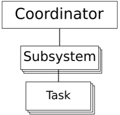
The components that characterise this pattern are shown in Figure 2. Tasks represent concurrent activities. A mode changer encapsulates several modes, and each mode encapsulates several mode-specific tasks. Only one mode per mode changer is active at any one time. There may also be persistent tasks, which are required to operate during all modes. The mode changer and any persistent tasks are controlled by a coordinator. Mode changes are typically requested by tasks from the currently active mode.
In terms of SCJ, a mode changer can be conveniently implemented as a mission sequencer, and each mode as a mission. The tasks can be realised as SCJ schedulable objects. The coordinator component also has a natural correspondence with a mission, often the main mission, which registers the persistent tasks and the mode changer, and controls their operation.
Example Application
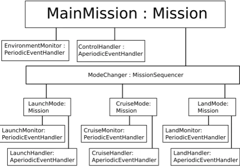
An example application that uses this pattern is an idealised Space Shuttle1, as
illus-trated in Figure 3. It has three modes, each associated with a phase of its opera-tion. Each mode has several schedulable objects that are only active during that mode – only two are shown for each mode in Figure 3. In addition to the mode-specific
schedulables, there are two persistent schedulables shown, EnvironmentMonitor and
Coordinator
Mode Changer Task
Mode
[image:6.595.192.403.70.222.2]Task
Figure 2: Multiple-Mode Operations Pattern
ControlHandler, which are active throughout all the modes.
MainMission : Mission
ModeChanger : MissionSequencer EnvironmentMonitor :
PeriodicEventHandler
ControlHandler : AperiodicEventHandler
LaunchMode: Mission
CruiseMode: Mission
LandMode: Mission
LaunchMonitor: PeriodicEventHandler
LaunchHandler: AperiodicEventHandler
CruiseMonitor: PeriodicEventHandler
CruiseHandler: AperiodicEventHandler
LandMonitor: PeriodicEventHandler
LandHandler: AperiodicEventHandler
Figure 3: Space Shuttle with Moded Operations
Adequacy of SCJ Support
Using missions to support individual modes of operation and mission sequencers to support the mode-change controllers has two main advantages. The first is that encap-sulating each mode in a mission enhances the modularisation of the SCJ program and the traceability of its structure to its architectural model. This is important when each mode is a significant software component in its own right.
The second advantage is that SCJ supports a well-defined (if somewhat complicated – see Section 5) process for mission termination, where schedulables can complete their current release before the mission completes. This is usually what is required when
mode change requests areplanned events. (Planned mode changes occur at well defined
points in a system’s operation. In contrast,unplanned mode changes usually occur as a
result of error conditions being detected. Such errors may be anticipated, but the time of their occurrence can not be predicted. Hence the time at which a mode change is required cannot be predicted.)
[image:6.595.175.421.303.474.2]execute a new mode, it is necessary to create all the new objects (that are to reside in the mission memory) during the initialization phase of the mission (mode). Hence, for unplanned mode changes or applications that require fast and predictable planned changes, there may be some efficiency or latency concerns.
In addition, there is no automatic single release time for all the schedulable objects in the application. The schedulable objects in the initial mode start at a different time from the persistent schedulable objects. To create a single start time, it is necessary to use absolute-time offsets for all periodic handlers.
For timing analysis, the mission sequencer, implementing the mode changer, must be viewed as an aperiodic activity whose minimum inter-arrival time is equal to the minimum time between mode change requests. Its deadline represents any time con-straints on the mode change operation. As an SCJ mission sequencer is a managed
event handler, it only has a priority; it does not have any release parameters. These
must be captured outside of the SCJ program and used in any schedulability analysis. We discuss this concern further in Section 4.
Finally, it is not easy to provide the runtime scheduling needed to support composi-tional time analysis of the application, as SCJ does not support hierarchical scheduling. SCJ schedules persistent schedulable objects in competition with mode-specific schedu-lable objects. Hence, the whole application must be analysed in each mode along with each mode transition. We discuss this issue in Sections 2.2 and 4.3 below.
2.2 The Independently Developed Subsystem Pattern
Overview
Assembling systems that are composed of independently developed subsystems, each encapsulating related behaviours, is an important approach to developing systems that are more complex than those typically developed for Level 1. The ability to create nested mission sequencers at SCJ Level 2 is the key to supporting this approach to constructing systems.
Architecture Components
The software architecture that characterises this pattern is shown in Figure 4. The sub-systems are all controlled by a coordinator. Subsub-systems may contain other subsub-systems. Typically, each subsystem is, or can be, independently developed and contains several tasks that perform related behaviours.
In terms of SCJ each subsystem can be decomposed into a mission sequencer and a single mission that manages the tasks within that subsystem. Each task can then be implemented by an appropriate managed schedulable: mission sequencer, thread, or handler. In this setting the coordinator component corresponds naturally to a mission, often the main mission, that registers the mission sequencers of each subsystem.
Example Application
A good example of this pattern is the railway system described by Hunt and Nilsen [20]:
Coordinator
Subsystem
[image:8.595.237.359.71.187.2]Task
Figure 4: The Independently-Developed Subsystem
responsible for honouring the train segment authorizations that are granted to it. Note that rail segment control addresses multiple competing concerns. On the one hand, there is a desire to optimize utilization of railway resources. This argues for high speeds and unencumbered access. On the other hand, there is a need to assure the safety of rail transport. This motivates lower speeds, larger safety buffers between travelling trains, and more conservative sharing of rail segments.”
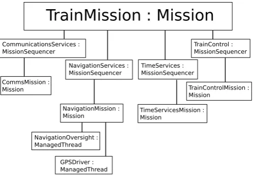
The example considers the structure of the on-board software (illustrated in Figure 5), which supports the following requirements:
• maintain reliable and secure communication with the central rail traffic control
authority — the CommunicationService subsystem;
• monitor progress of the train along its assigned route — the NavigationService
subsystem;
• control the train’s speed in accordance with scheduled station stops, rail segment authorizations, local speed limit considerations, and fuel efficiency objectives — theTrainController subsystem;
• infrastructure support for maintaining global time — theTimeServicessubsystem.
In the implementation described in [20], each of these subsystems is realised as a nested mission sequencer registered to the main mission (TrainMission), and each subsystem controls a single mission that registers the subsystem-specific managed schedulables. There are multiple tiers of nested mission sequencers within the subsystems. Each tier represents further subsystems that can be developed independently. For brevity, Figure 5 only shows two of the subsystem-specific managed schedulables and omits the deeper tiers of nested mission sequencers.
Adequacy of SCJ Support
TrainMission : Mission
CommunicationsServices : MissionSequencer
TimeServices : MissionSequencer NavigationServices :
MissionSequencer CommsMission :
Mission
NavigationMission : Mission
TrainControlMission : Mission
NavigationOversight : ManagedThread
GPSDriver : ManagedThread
TrainControl : MissionSequencer
[image:9.595.174.423.70.243.2]TimeServicesMission : Mission
Figure 5: Railway System with Multiple Subsystems
The second issue has already been mentioned in Section 2.1. When a system is composed of subsystems, there is no automatic common release time for all the schedu-lable objects. If required, this has to be programmed explicitly. For multiple nested sequencers, this can become cumbersome because the system start time needs to be passed down to all schedulable objects in the system.
Whilst the above limitations can be seen as minor, the third limitation, which we discuss next, is more significant. Neither SCJ nor the RTSJ directly support hierar-chical scheduling. Hence it is difficult to achieve decomposability of timing constraints when subsystems are independently developed. The RTSJ does support the notion of processing groups, which allow several schedulable objects to share a CPU budget, but these are too general and difficult to use in a multiprocessor environment [6, 39]. Hierarchical scheduling techniques for single processor and partitioned multiprocessor systems are well established [11] and techniques are beginning to emerge for globally scheduled multiprocessor systems [5, 12]. The lack of such a facility in SCJ severely limits its use in supporting the timing analysis of applications composed according to the independently-developed subsystem pattern. We return to this issue in Section 4.3. The final issue with the functionality of SCJ, in relation to this programming pat-tern, is that the API supports a request to terminate a mission sequencer. The intention of this facility is to allow a schedulable object within a mission to request not only its mission to be terminated, but also the whole sequence of missions (of which it is part) to be terminated. The concern with the facility is that it can be misused by a schedulable to terminate an arbitrary mission sequencer. This complicates the semantics of the ter-mination protocol needed to support mission terter-mination and breaks the encapsulation of the mission concept. We return to this issue in Sections 4.4 and 5.
3
Using Managed Threads
3.1 Non-Standard Release Profiles
It is impossible to anticipate every possible scenario in which a schedulable object might need to be released. Here, we consider three common scenarios and discuss the diffi-culties of implementing them at Level 1. We choose one of these to illustrate how implementation using Level 2 is possible.
A Periodic Activity Released by an Event
In SCJ, a periodic activity is either released immediately when it is started, or released after an absolute or relative delay from when it is started. There is no possibility of releasing a periodic activity via notification from another schedulable object or, indeed, an interrupt. However, it can be desirable for the initial release of a periodic activity to be triggered by a notification from another schedulable object, the absence of such a notification, or an interrupt. For example, the implementation of a task controlling a mechanical system that requires periodic updates but is started by an aperiodic button press can benefit from such a release pattern.
The above discussion suggests that the Level 1 support for periodic event handlers is not flexible enough to cope with anything other than simple time-released periodic
activities. Simply introducing theObject.wait()and Object.notify()methods into
Level 2, to allow a periodic handler to wait for a notification, is not sufficient. The problem is that deadline monitoring of event handlers starts from when the handler is first released. In SCJ, deadlines cannot be dynamically changed, so it is not possible to set an initial deadline and then change it after the notification has occurred.
The introduction of managed threads at Level 2, on the other hand, allows these more general release patterns to be addressed, as managed threads allow programmers to implement their own release mechanisms. We consider, for example, the periodic managed thread released by software notification illustrated in Figure 6, which shows
an abstract extension of the ManagedThread class. The firstRelease method (lines
18-23) is called during the mission to indicate that the periodic activity should now
start. The abstractwork method declared on line 35 must be overridden to provide the
functionality to be called each period. Therunmethod (lines 38-47) is final and waits for the initial release before calling the work method periodically. This example illustrates the added flexibility that is available at Level 2; the periodic thread in Figure 6 can not be programmed at Level 1.
Another example of a more complicated release pattern that can only be programmed in SCJ at Level 2 is the thruster control system described by Wellings [38, Page 235]. Here, an astronaut activates the thruster and supplies a duration for the engine “burn”. The control of the engine itself requires a periodic activity to avoid the mechanical drift of valves. This requires an activity that is released by an event, executes periodically for a certain duration (determined either by time itself or by another event), and then waits to be started again. For the same reasons as those described above for an event-released periodic activity, the only way this release pattern can be supported in SCJ is with
managed threads usingObject.wait()and Object.notify().
On the other hand, it should be noted that managed threads are a simplified version of the RTSJ’s no-heap real-time thread, with the following restrictions: there is no
automatic release mechanism (that is, no support forwaitForNextPeriod) and there is
1 public a b s t r a c t class P e r i o d i c T h r e a d e x t e n d s M a n a g e d T h r e a d {
2
3 p r i v a t e A b s o l u t e T i m e n e x t R e l e a s e ; // the next r e l e a s e time of this t h r e a d
4 p r i v a t e A b s o l u t e T i m e n e x t D e a d l i n e ; // the next d e a d l i n e of this t h r e a d
5 p r i v a t e final int period ;
6 p r i v a t e final int d e a d l i n e ;
7 p r i v a t e D e a d l i n e M i s s H a n d l e r d e a d l i n e M i s s D e t e c t i o n ;
8 p r i v a t e M i s s i o n m y M i s s i o n ; // this t h r e a d ’ s c o n t r o l l i n g m i s s i o n
9 p r i v a t e b o o l e a n h a d F i r s t R e l e a s e = false ;
10
11 public s y n c h r o n i z e d void f i r s t R e l e a s e () {
12 h a d F i r s t R e l e a s e = true ;
13 notify ();
14 n e x t R e l e a s e = Clock . g e t R e a l t i m e C l o c k (). g e t T i m e ( n e x t R e l e a s e );
15 n e x t D e a d l i n e . set ( n e x t R e l e a s e . g e t M i l l i s e c o n d s () + d e a d l i n e );
16 d e a d l i n e M i s s D e t e c t i o n . s c h e d u l e N e x t R e l e a s e T i m e ( n e x t D e a d l i n e );
17 }
18
19 p r i v a t e s y n c h r o n i z e d b o o l e a n w a i t F i r s t R e l e a s e () {
20 while (! h a d F i r s t R e l e a s e ){
21 try { wait (); }
22 // or H i g h R e s o l u t i o n T i m e . w a i t F o r O b j e c t ( this , t i m e o u t )
23 // if a t i m e o u t is also r e q u i r e d
24 catch ( I n t e r r u p t e d E x c e p t i o n ie ) { // m i s s i o n is to be t e r m i n a t e d
25 return false ;
26 }
27 }
28 return true ;
29 }
30
31 p r o t e c t e d a b s t r a c t void work ();
32 // o v e r r i d e this to p r o v i d e the f u n c t i o n of the t h r e a d
33
34 public final void run () {
35 if ( w a i t F i r s t R e l e a s e ()) {
36 while (! m y M i s s i o n . t e r m i n a t i o n P e n d i n g ()) {
37 n e x t R e l e a s e . add ( period ,0);
38 work ();
39 n e x t D e a d l i n e . add ( period ,0);
40 d e a d l i n e M i s s D e t e c t i o n . s c h e d u l e N e x t R e l e a s e T i m e ( n e x t D e a d l i n e );
41 S e r v i c e s . delay ( n e x t R e l e a s e ); // w a i t F o r N e x t P e r i o d
42 }
43 }
44 }
45 }
Consumers in a Producer-Consumer System
Another common release pattern is where a producer schedulable object generates data that must be processed by a consumer schedulable object. Typically this data may come in bursts, and the consumer should process all the data as quickly as possible and block when there is no data available. These requirements cannot be met at Level 1, since it does not support a queue of outstanding release events for aperiodic event handlers. Level 2 allows this release pattern to be programmed using managed threads.
Background Activities: Run as Fast as You Can
There are occasions where background activities are required to run as fast as possible. This is the case, for example, of a logging task that is required to process data from application logs whenever the scheduler allows it access to the processor. There is no notion of release events for these activities (other than their initial start). These activities can be programmed with Level 1 functionality using either an aperiodic event handler that is released only once, or a one-shot event handler with no start wait time. Both of these options, however, are a misuse of these mechanisms. Although there is no negative consequence for this misuse, a managed thread is a better abstraction to support this requirement.
3.2 Suspension-based Waiting for IO where Busy-Waiting is Inappro-priate
In many systems, a device driver busy-waits for its associated device input (or output) to complete. This is because the expected delay is small and context switching away from the driver is considered inefficient. There are ways to integrate this delay into the scheduling of the driver (see [7, Section 14.6]), and allowing the driver to delay when it has no other activity to perform may also be appropriate. On the other hand, when this delay is a relatively significant amount of time, it is necessary to allow the system to schedule some alternative activities. Since it is not possible to have a suspension-based delay at Level 1, this requirement can only be implemented at Level 2.
3.3 Encapsulation of State Information
Another characteristic that differentiates managed threads from event handlers is their use of memory. An event handler has its private memory area cleared at the end of each release, which means that state that must persist across releases must be saved in an outer memory area. A managed thread, however, only has its memory area cleared
when it exits its run() method (that is, it terminates). This means that data can be
stored locally and preserved over successive application-implemented ‘releases’ of the thread.
Of course, the effect of these two approaches is the same. The thread’s memory area can last for as long as the memory area of its controlling mission, which is where persistent data used by an event handler is normally stored. However, this ability to encapsulate state is important from a software engineering perspective, since storing data that is private to a schedulable object in the mission memory of its controlling mission makes this data more widely visible than it should be.
1 R u n n a b l e R = new R u n n a b l e () {
2 public void run () { work (); }
3 };
4
5 public final void run () {
6 if ( w a i t F i r s t R e l e a s e ()) {
7 while (! m y M i s s i o n . t e r m i n a t i o n P e n d i n g ()) {
8 n e x t R e l e a s e . add ( period ,100) ;
9 M a n a g e d M e m o r y . e n t e r P r i v a t e M e m o r y ( p r i v a t e M e m o r y S i z e , R );
10 n e x t D e a d l i n e . add ( period ,100);
11 d e a d l i n e M i s s D e t e c t i o n . s c h e d u l e N e x t R e l e a s e T i m e ( n e x t D e a d l i n e );
12 S e r v i c e s . delay ( n e x t R e l e a s e );
13 }
14 }
[image:13.595.76.425.78.224.2]15 }
Figure 7: Augmented Periodic Schedulable Object
buffer in mission memory, which another schedulable object uses to write the system state changes to disk. If the logging schedulable objects are event handlers, the local buffers cannot be stored in their per-release memory areas, as such areas are cleared at the end of each of their releases. They need to be stored in the mission memory. Using managed threads, the local buffers can be stored in the per-release memory areas, as these are not cleared until their associated managed threads terminate. In addition, the local buffers do not become exposed to access by other schedulables.
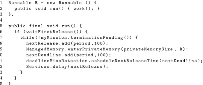
Application-implemented releases, such as those programmed in Figure 6, can also be augmented to use a nested private memory area for objects that can be cleared at the end of each application-implemented release. This is illustrated in Figure 7, which
just shows the augmentedrun()method (and an associated runnable) of lines 38-47 of
Figure 6.
4
Revisiting the SCJ Level 2 Support
Sections 2 and 3 have explored some of the application requirements where the use of Level 2 functionality is desirable. Here, we review the issues identified as potential causes of problems, and explore changes that can be made to the SCJ specification to avoid these problems.
4.1 Managed Thread Termination
In SCJ, a managed thread terminates when it returns from its run() method. In
Sec-tion 3 we illustrate how this simple release pattern can be adapted, using Level 2 fea-tures, to provide more complicated release patterns. Figure 6 shows the example of a periodic thread that is first released by software notification using the Object.wait() method (on line 18). With this approach, however, if our periodic thread is released and is waiting for its software notification when its controlling mission begins termination,
then the thread may not finish its current release – its run() method may remain
ac-tive. More generally, this applies to any schedulable object that is using the suspension features available at Level 2; if they are waiting when their controlling mission begins termination, then their release may not finish.
SCJ [24] defines the following activities to be performed on receipt of a mission termination request:
• invoke signalTermination() on each managed schedulable object that is regis-tered for execution within this mission;
• disable all periodic event handlers associated with this mission so that no further firings occur;
• disable all aperiodic event handlers, so that no further firings are honoured;
• clear the pending release event (if any) for each event handler so that the event
handler can be effectively shut down following completion of any event handling that is currently active;
• wait for all of the managed schedulable objects associated with this mission to
terminate their execution;
• invoke the ManagedSchedulable.cleanUp() method for each of the managed
schedulable objects associated with this mission; and,
• invoke the cleanUp()method associated with this mission.
We note that this list does not require invoking the interrupt() methods of all the
managed schedulables, which would cause all blocked managed schedulables to wake up with an exception and hence expedite termination. This has to be programmed by
applications using the Mission.terminationHook() method, and can be inconvenient
when the mission has many schedulable objects.
To aid the termination of managed threads and schedulables that are suspended when a termination request is received, we propose that either the SCJ infrastructure interrupts all schedulable objects associated with the mission or that all the schedulable objects associated with the mission are informed of a pending termination request. The latter proposal can be achieved via a new method (terminationSignalled()), which each managed schedulable object must implement. The intention of this method is to allow the programmer to manually interrupt those schedulable objects that may be blocked when mission termination is signalled.
4.2 Deadlines on Mission Sequencers
As discussed in Section 2.1 an SCJ mission sequencer does not have any release parame-ters. Therefore, it cannot have an associated deadline or deadline-miss handler. Systems that support multiple modes of operations often have deadlines associated with the mode changes. Hence, at Level 2 it is appropriate to allow some form of deadline-miss handler to execute if the mode change does not occur promptly.
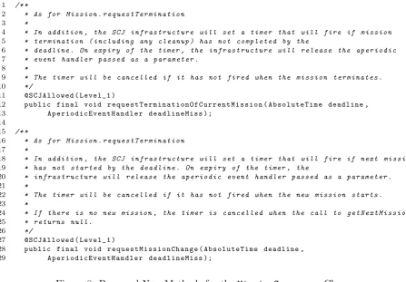
Adding aperiodic release parameters to mission sequencers seems to undermine the mission programming model, particularly for sequencers that support a single non-terminating mission. Instead, what we propose is to add the methods shown in
Fig-ure 8 to the MissionSequencer class. These methods identify deadline-miss handlers
for mission termination and start. We note that, since mission changes can also occur in Level 1, these facilities might also prove useful in that context.
4.3 Support for Compositional Timing Analysis
1 /* *
2 * As for M i s s i o n . r e q u e s t T e r m i n a t i o n
3 *
4 * In addition , the SCJ i n f r a s t r u c t u r e will set a t i m e r that will fire if m i s s i o n
5 * t e r m i n a t i o n ( i n c l u d i n g any c l e a n u p ) has not c o m p l e t e d by the
6 * d e a d l i n e . On e x p i r y of the timer , the i n f r a s t r u c t u r e will r e l e a s e the a p e r i o d i c
7 * e v e n t h a n d l e r p a s s e d as a p a r a m e t e r .
8 *
9 * The t i m e r will be c a n c e l l e d if it has not f i r e d when the m i s s i o n t e r m i n a t e s .
10 */
11 @ S C J A l l o w e d ( L e v e l _ 1 )
12 public final void r e q u e s t T e r m i n a t i o n O f C u r r e n t M i s s i o n ( A b s o l u t e T i m e deadline ,
13 A p e r i o d i c E v e n t H a n d l e r d e a d l i n e M i s s );
14 15 /* *
16 * As for M i s s i o n . r e q u e s t T e r m i n a t i o n
17 *
18 * In addition , the SCJ i n f r a s t r u c t u r e will set a t i m e r that will fire if next m i s s i o n
19 * has not s t a r t e d by the d e a d l i n e . On e x p i r y of the timer , the
20 * i n f r a s t r u c t u r e will r e l e a s e the a p e r i o d i c e v e n t h a n d l e r p a s s e d as a p a r a m e t e r .
21 *
22 * The t i m e r will be c a n c e l l e d if it has not f i r e d when the new m i s s i o n s t a r t s .
23 *
24 * If t h e r e is no new mission , the t i m e r is c a n c e l l e d when the call to g e t N e x t M i s s i o n
25 * r e t u r n s null .
26 */
27 @ S C J A l l o w e d ( L e v e l _ 1 )
28 public final void r e q u e s t M i s s i o n C h a n g e ( A b s o l u t e T i m e deadline ,
[image:15.595.74.522.77.388.2]29 A p e r i o d i c E v e n t H a n d l e r d e a d l i n e M i s s );
Figure 8: Proposed New Methods for the MissionSequencer Class
a single mission, which controls that subsystem’s schedulable objects, as detailed in Section 2.2. Hence, we consider the mission sequencer as the top of the subsystem.
Hierarchical scheduling (and its associated schedulability analysis) is a well estab-lished technique that facilitates composition when components have real-time attributes (such as deadlines). Unfortunately, hierarchical scheduling is supported by neither SCJ nor the RTSJ. This is possibly because of the lack of support by real-time operating system vendors. We propose incorporating two elements of hierarchical scheduling into SCJ to improve its support for independently-developed subsystems and components: CPU budgets, to implement execution-time servers; and multi-level priorities, to isolate the scheduling of subsystems.
In the proposed approach, constructing a system made of subsystems can be achieved broadly in three steps. First, each subsystem is allocated an execution-time server, which is given a capacity, a priority order, and a replenishment period. These parameters need to be assigned carefully to obtain good schedulability [10]. Next, the priority ordering of the schedulable objects in each subsystem must be determined. Finally, an integration step assigns concrete priorities to the schedulable objects based on their priority ordering and the priority order of their server.
The schedulable objects within a subsystem are only scheduled for execution (in priority order) when their execution-time server server would be scheduled at the top level (and has available capacity). Once the parameters of the execution-time servers and the schedulables are set, the program needs to be analysed to determine schedulability at both the system and subsystem levels. We note that there is a relationship between the priorities of the execution-time server and of the subsystem’s schedulable objects.
4.3.1 CPU Budgets
The first aspect of hierarchical scheduling we require is that each subsystem is allocated a budget, which is consumed whenever one of its schedulable objects is executing, and a period after which its budget is replenished. When a subsystem’s budget has been totally consumed, all of its associated schedulable objects are suspended until its next replenishment occurs. In the RTSJ, this functionality can be supported by processing groups, if all the schedulable objects run on the same CPU.
Implementations of the RTSJ that support processing groups ensure that members of a group, collectively, are not be given more CPU time per period than their group’s
bud-get. When supported, the RTSJ implements the ProcessingGroupParameters class,
which is associated with each schedulable object in the processing group. This allows the RTSJ’s schedulable objects to share a budget while retaining their individual priorities, deadlines, and periods.
Because processing groups support the requirements for compositional timing anal-ysis, one possible solution is for SCJ to implement the following restricted version of the
RTSJ ProcessingGroupParameters class, where the deadline of the processing group
is equal to its replenishment period.
1 p a c k a g e javax . s a f e t y c r i t i c a l ;
2
3 public class P r o c e s s i n g G r o u p P a r a m e t e r s {
4 public P r o c e s s i n g G r o u p P a r a m e t e r s ( H i g h R e s o l u t i o n T i m e start ,
5 R e l a t i v e T i m e r e p l e n i s h m e n t P e r i o d , R e l a t i v e T i m e budget ){
6 ...
7 }
8 ...
9 }
However, this technique inherits the limitation that the missions encapsulated within a mission sequencer need to execute on the same processor.
4.3.2 Simulating Multi-Level Priorities
The second aspect of hierarchical scheduling that we require is multi-level priorities, which can be simulated in SCJ by manipulating the priorities of mission sequencers and schedulable objects. We propose:
• using the priority of each mission sequencer to define a priority range: from the
priority of this mission sequencer to the priority of the next highest priority mission sequencer, and;
• transposing the priorities of all the schedulable objects in this subsystem into this range, while maintaining their original priority order, to ensure that they only run when their subsystem has the highest priority of all the subsystems.
This priority manipulation is performed statically, before the program is executed, in the integration step mentioned above. It may be the case that mission sequencer’s priorities must be changed during integration to accommodate the schedulable objects. This is allowed as long as the priority order of the mission sequencers is maintained.
Period (ms) Budget (ms)
Server 1 100 40
[image:17.595.198.394.71.117.2]Server 2 50 15
Figure 9: Execution-Time Server Parameters
At the top level, the execution-time server the subsystems associated withServer1 has a replenishment period of 100 milliseconds and a budget of 40 milliseconds. The
execution-time server of the subsystem associated with Server2 has a replenishment period of 50
milliseconds and a budget of 15 milliseconds. The top-level is schedulable when the priority of Server2 is greater than the priority of Server1.
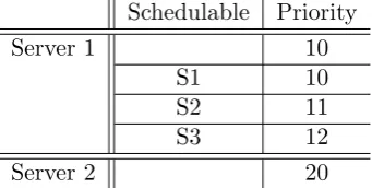
Now, we suppose that the subsystem associated withServer1 contains three
schedu-lable objects, S1, S2, and S3, which require a priority ordering where S3 has a higher priority than S2, which has a higher priority than S1. During system integration, the priorities of the servers and schedulables could be assigned so that the priority ofServer2 is greater than that ofServer1 plus 3 in order to allow the priorities of the schedulable objects to be assigned between those of the two servers. An example of the priorities that can be assigned is shown in Table 10.
Schedulable Priority
Server 1 10
S1 10
S2 11
S3 12
Server 2 20
Figure 10: Execution-Time Server and Schedulable Priorities
This concrete priority assignment simulates multi-level priorities, because the schedula-bles of the subsystem associated withServer1 are not able to run ifServer2 is executing.
4.3.3 Incorporation into SCJ
As detailed above, to support CPU budgets, SCJ needs to implement processing groups, and SCJ can already support multi-level priorities, by manipulating the priorities of an application’s schedulable objects and mission sequencers. To aid integration of these two aspects of hierarchical scheduling into SCJ applications, a new subclass of mission sequencer can be added to encapsulate the concerns of a subsystem, as shown in the example below.
1 public class S u b s y s t e m e x t e n d s M i s s i o n S e q u e n c e r {
2 public S u b s y s t e m ( P r i o r i t y P a r a m e t e r s pri , S t o r a g e P a r a m e t e r s storage ,
3 P r o c e s s i n g G r o u p P a r a m e t e r s params , int p r i R a n g e ){
4 ...
5 }
6 ...
7 }
The constructor above takes a ProcessingGroupParameters object, as described in
[image:17.595.213.384.343.429.2]and of pri + priRange define the prioirity range for schedulable objects encapsulated by this subsystem.
4.4 Mission Sequencer Termination
In Section 2.2, we argue that allowing arbitrary schedulables to request the termination of an arbitrary mission sequencer violates the encapsulation supported by missions. We propose that schedulable objects are only allowed to request that their controlling mis-sion is terminated. The mismis-sion itself then has the responsibility of deciding whether to request its sequencer to terminate. This gives a more structured approach to termina-tion.
We propose removing the requestSequencerTermination()method, which allows
a request to terminate a mission sequencer, to enforce this more structured termination policy. Instead, we recommend that the mission cleanup phase indicates whether its sequencer should continue with the next mission or terminate. For that, we propose that
Mission.cleanUp() return a boolean value, which is passed to the mission sequencer
to determine if the mission sequencer should continue or terminate.
We investigate the impact of this change in the next section. As the termination protocol is one of the more complex features of SCJ Level 2 programs, we consider formal models of the SCJ termination protocol for both the current specification and for the protocol that we propose here.
5
Formalisation of Level 2
In this section we present: a formal model of the current termination protocol as pre-sented in the SCJ draft specification [24], in Section 5.2; a formal model of the termi-nation protocol incorporating our proposed changes, in Section 5.3; and a comparison of these two models, in Section 5.4. Our models are written in the state-rich process algebra Circus, for which a model of SCJ Level 1 already exists [40]. In Section 5.1 we
give a brief overview of theCircus notation.
With these models we show that the current termination protocol is more compli-cated than necessary. Indeed, it was the process of formally modelling SCJ Level 2 that first illuminated the complexities of the mission sequencer termination protocol. These complications only become apparent at Level 2 because of its capacity to nest mission sequencers arbitrarily deeply, which means that mission sequencers can be terminated by schedulables both above and below themselves in the program’s hierarchy at any point during the execution phase.
5.1 Circus Introduction
Circus [8] combines elements from CSP [19], Z [34], and a refinement calculus [25] to
allow modelling of both state and patterns of interaction. Figure 11 sketches the BNF
description of the syntax of Circus. Below, we describe the elements of the syntax
pertinent to the discussion of our formal model. A comprehensive account ofCircuscan
be found in [27].
Circusprograms, defined in Figure 11 by the syntactic categoryProgram, are formed
by a sequence of Circus paragraphs. Each Circus paragraph, defined in Figure 11 as
elements of CircusPar, may be either a Z paragraph (the Par category), a channel
dec-laration, a channel set decdec-laration, or a process declaration. The syntactic category N
Circusprograms use bi-directional channels to allow their processes to communicate;
we discuss the different types of communications later in the section. All of the channels
used in a Circus program must be declared. Channel declarations are defined by the
CDecl syntactic category in Figure 11. Here, Exp is the category of Z expressions. If a channel takes any parameters, their types must be declared. For convenience, channels
my be collected into a channel set – defined by theCSExp category. Channel sets allow
easy specification of the channels used to interact with a process.
Each Circus process has a name and a body (process N=b ProcDef) and may take
parameters (Decl•ProcDef). In our model, this is used where, for example, the process modelling a mission or a mission sequencer takes a parameter representing its unique
identifier. Hence, for example, processMissionFW =b mission : MissionID • . . .
de-clares the mission process with a parametermission of type MissionID.
The body of a Circus process (begin PPar∗state SchemaExp PPar∗ •Actionend)
is delimited by thebeginandendkeywords; it may contain a state, which is modelled
using a Z schema; and some actions, modelled using a free combination of Z state
operations, constructs of a simple imperative language, and CSP constructs (PPar∗).
While Z schemas can be used to define data operations over the state of aCircusprocess
using predicates, assignments to variables can also be made directly (N+
:=Exp+
, from theCommand category in Figure 11).
A Circusprocess always has a main action at the end of the process after a •, that
dictates the combination of Z schemas and CSP actions that define the behaviour of the process; these actions may reference other local actions for the purpose of structure.
Both the state and actions of a Circus process are local to that process. This makes
Circus processes similar to classes in object-oriented programming, where a class has
some local variables and methods.
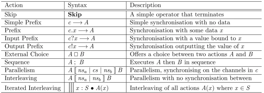
CSP has many operators that are adopted inCircus, which all belong to the syntactic
categoryCSPAction in Figure 11. Table 2 provides a description of the operators in this category that we use in our model, some of which are omitted in Figure 11. We describe these in more detail below to support the following discussion of our model.
Action Syntax Description
Skip Skip A simple operator that terminates
Simple Prefix c−→A Simple synchronisation with no data
Prefix c.x −→A Synchronisation with some data x
Input Prefix c?x−→A Synchronisation with a value bound to x
Output Prefix c!x −→A Synchronisation outputting the value ofx
External Choice A@B Offers a choice between two actions A and B
Sequence A; B Executes A thenB in sequence
Parallelism AJnsa |cs |nsbKB Parallelism, synchronising on the channels inc
Interleaving AJnsa |nsbKB Parallelism with no synchronisation between
[image:19.595.88.548.474.637.2]Iterated Interleaving
9
x :S •A(x) Interleaving of all actions A(x) wherex ∈STable 2: Syntax of Circus operators derived from CSP
A simple operator isSkip, which terminates and does nothing else. A prefixc−→A
waits for a communication on the channelc and then proceeds to behave like the action
A. If a channel has a parameter then this must be provided. The parameter can be
included as either an input (c?x−→A), an output (c!x−→A), or added to the channel name to indicate a specific communication on that channel (c.x−→A). This latter form
Program ::= CircusPar∗
CircusPar ::= Par | channel CDecl| channelset N=b CSExp |ProcDecl CDecl ::= SimpleCDecl |SimpleCDecl; CDecl
SimpleCDecl ::= N+
|N+
:Exp|[N+
]N+
:Exp| . . .
CSExp ::= {| |} | {|N+|} |N|CSExp∪CSExp |CSExp∩CSExp
| CSExp\CSExp
ProcDecl ::= process N=b ProcDef | . . .
ProcDef ::= Decl•ProcDef |Proc . . .
Proc ::= begin PPar∗ state SchemaExp PPar∗ •Action end
. . .
NSExp ::= { } | {N+} | N|NSExp∪NSExp|NSExp∩NSExp
| NSExp\NSExp
PPar ::= Par |N=b ParAction|nameset N=b NSExp ParAction ::= Action|Decl•ParAction
Action ::= |Command |N|CSPAction. . .
CSPAction ::= Stop |Chaos |Pred & Action|Action⊓Action
| Action
\
CSExp|;
Decl•Action. . .Comm ::= N CParameter∗
. . .
CParameter ::= ?N |?N:Pred |!Exp|.Exp
Command ::= N+
:=Exp+
| if GActions fi | var Decl•Action
| val Decl•Action. . .
GActions ::= Pred−→Action|Pred−→Action@GActions
it is parametrised by the identifier of the Circus process to which it belongs. A related
operator is sequential composition;, which connects any two processes, instead of just a
channel communication and a process like the prefix operator−→. HenceA; Bexecutes
the actionA until it terminates and then continues on to executeB.
The external choice operator @ allows an action to offer its environment the choice
of two different channel communications. Hence c1 −→A @ c2−→B proceeds to A
if there is a communication on c1 or B if there is a communication on c2. Circus
also contains a simple conditional statement as shown in the definition of the syntactic categoryCommandin Figure 11. It takes a familiar if. . . then. . . else form. Henceif(x =
TRUE)−→A 8 (x = FALSE)−→B fi performs the action A if x =TRUE and the
actionB ifx =FALSE.
Two actions A and B may be placed in parallel: AJnsa | cs | nsbKB, specifies a
synchronisation set of channelscs over which they both have to agree to communicate,
and name sets describing the variables that each side of the parallelism may alter that must be disjoint to avoid write conflicts. Hence, in the execution ofAJ∅| {|a,b|} |∅KB,
Aand B perform their actions in parallel with each other, but they must both agree to
communicate on the channels a and b at the same time; further, the use of the empty
set (∅) indicates that neitherAnorB can alter any variables.
5.1.1 SCJ in Circus
A formal model of SCJ Level 1 has been produced [40] to allow the translation of
arbitrary SCJ programs into Circus in order to facilitate analysis. The Circus models
are composed of a model of the infrastructure classes of SCJ – the ‘Framework Model’ – which remains the same and is reused for each translation, and a model of the code provided by the application – the ‘Application Model’ – which changes for each new
program translated. The Framework Model encapsulates the unchanging aspects ofany
SCJ program, whereas the Application Model is generated afresh each time to model a
specific SCJ Level 1 program.
A Circus model of SCJ Level 2 is in development, based on the approach taken by
the Level 1 model; therefore, it has a Framework and an Application component. The Level 2 model has Circusprocesses for each of the main infrastructure classes in
SCJ, and each object in the program is represented by its own instance of the relevant
Circus process. Generally speaking, each Circus process retains the name of the SCJ
class it models, suffixed with “FW” for framework processes and “App” for application processes.
The methods of each of the objects that we model are represented byCircusactions.
Ordinarily, a call to a method is modelled by two channels: a channel modelling the call
to the method, suffixed by Call; and a channel modelling the return from the method,
suffixed by Ret. For example, mission sequencers need to know that their current
mis-sion’s initialize() method has completed before continuing. The action modelling
theinitialize()method, therefore, starts with a synchronisation oninitializeCall and
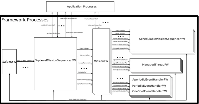
terminates with a synchronisation oninitializeRet. However if, in our model, the caller of the method does not require that the method returns before it continues, then a call to that method is modelled by a single channel.
Framework Processes
SafeletFW TopLevelMissionSequencerFW MissionFW
SchedulableMissionSequencerFW
ManagedThreadFW
AperiodicEventHandlerFW
start_toplevel_sequencer
PeriodicEventHandlerFW OneShotEventHandlerFW
start_mission done_mission requestTermination
initializeRet signalTerminationCall signalTerminationRet
start_mission done_mission signalTerminationCall signalTerminationRet cleanupSchedulableCall cleanupSchedulableRet
signalTerminationCall signalTerminationRet cleanupSchedulableCall cleanupSchedulableRet signalTerminationCall signalTerminationRet cleanupSchedulableCall cleanupSchedulableRet
done_toplevel_sequencer
Application Processes
...
...
...
...
...
...
...
getNextMission Call getNextMission Ret
cleanup SchedulableCall
cleanup SchedulableRet cleanupMission Call
[image:22.595.92.506.69.285.2]cleanupMission Ret
Figure 12: Level 2 Model Structure
ellipses, the three types of event handlers are represented by the single component at the bottom right of the figure, and all application processes are represented by the single component shown at the top of the figure. Because a mission sequencer can be used in two contexts at Level 2 – both as a mission sequencer at the top of the program hierarchy and as a schedulable object nested inside a mission – this class is modelled by
two processes: one for the top-level mission sequencer, TopLevelMissionSequencerFW;
and one for a schedulable mission sequencer, SchedulableMissionSequencerFW. This
simplifies both processes because they each only have to be involved in communications
relevant to their context. The MissionFW and the processes representing the
schedu-lable objects may have multiple instances in one model. Each of the SCJ methods that
we model is represented by a CSP action in the relevantCircus process.
5.2 Model of the Current Termination Protocol
The current termination protocol requires very complex models of the mission sequencer
process. This holds for both theTopLevelMissionSequencerFW and theSchedulableMissionSequencerFW.
Complexity arises because mission sequencers may be terminated at arbitrary times dur-ing their execution. In this section we describe our model of the protocol and explain the source of its complexity.
5.2.1 Top Level Mission Sequencer
The TopLevelMissionSequencerFW process has one parameter,sequencer, which is the identifier of this mission sequencer process, and two state components: currentMission, which holds the identifier of the mission this sequencer is currently executing; and
terminating, which is a boolean value that records if this mission sequencer has been
and is shown below.
GetNextMission =b
getNextMissionCall.sequencer−→ getNextMissionRet.sequencer?next−→ currentMission :=next;
StartMission;
if terminating = FALSE−→
GetNextMission
8terminating = TRUE−→
Skip
It communicates with the application model using the channelsgetNextMissionCall and
getNextMissionRet to get the identifier of the next mission that this mission sequencer
should execute. This identifier is stored in the variable currentMission. Then the
StartMission action is called; it uses the start mission channel to start the current mission. This action is defined as follows.
StartMission =b
if currentMission 6= nullMissionId−→
start mission.currentMission−→ initializeRet.currentMission−→
RequestSequenceTermination
J{terminating} | {|end termination|} |∅K done mission.currentMission−→
end termination.sequencer−→Skip
!
8currentMission = nullMissionId−→
terminating :=TRUE ; Skip fi
Once the current mission enters its execution phase (indicated by the communication on the initializeRet channel) the RequestSequenceTermination action is offered in parallel
with a communication on thedone missionchannel, which is used by the current mission
to indicate that it has terminated.
The parallelism here specifies that RequestSequenceTermination and the
communi-cations in the brackets below the parallel operator synchronise onend termination, that
RequestSequenceTermination alters the terminating variable, and the behaviours below the parallel operator do not alter any variables.
Once a communication on done mission occurs, StartMission waits for the action
RequestSequenceTermination to be ready to engage in end termination; this ends both sides of the parallelism and control returns to theGetNextMissionaction. GetNextMission
then checks the value of the variable terminating, which is set
in the RequestSequenceTermination action shown in Section 5.2.3, to determine
whether it should recurse or exit.
5.2.2 Schedulable Mission Sequencer
It has a sequencer parameter and a currentMission state component, like the
top-level mission sequencer process. Instead of terminating it has two state components:
terminatingAbove, which indicates if this mission sequencer’s controlling mission has asked it to terminate, andterminatingBelow, which indicates if this mission sequencer’s current mission (or one of its managed schedulables) has asked it to terminate. Two variables are required because we have to treat the requests for termination differently, depending on their source. With two variables, we can model the different protocols separately.
Here, the GetNextMission action behaves identically to that used in the process
TopLevelMissionSequencerFW (Section 5.2.1) aside from the conditional statement
be-low, which checks bothterminatingAboveandterminatingBelow to handle the possibility
of the nested mission sequencer being asked to terminate from above or below itself in the program hierarchy.
if terminatingAbove = FALSE ∧ terminatingBelow = FALSE−→
GetNextMission
8terminatingAbove = TRUE ∨ terminatingBelow = TRUE−→
Skip
The StartMission action of the SchedulableMissionSequencerFW, shown below, con-tains a parallelism of three actions that offer the choice of waiting for its
control-ling mission to signal its termination (handled by the SignalTermination action), the
RequestSequenceTermination action (which we discuss in Section 5.2.3), and waiting for
its current mission to communicate its termination ondone mission.
StartMission =b
ifcurrentMission 6=nullMissionId−→
start mission.currentMission−→ initializeRet.currentMission−→
SignalTermination
J{terminatingAbove} | {|end terminations|} |terminatingBelowK
RequestSequenceTermination
J{terminatingAbove,terminatingBelow} | {|end terminations|} |∅K
done mission.currentMission−→ end terminations.sequencer−→
Skip
8currentMission=nullMissionId−→
terminating :=TRUE
fi
terminate.
SignalTermination =b
end terminations.sequencer−→Skip
@
signalTerminationCall.sequencer−→ terminatingAbove :=TRUE;
requestTermination.currentMission−→ signalTerminationRet.sequencer−→
Skip
;end terminations.sequencer−→
Skip
The SignalTermination action handles the nested mission sequencer being
termi-nated from above and the done mission communication handles the nested mission
se-quencer’s current mission telling it to terminate from below. TheRequestSequenceTermination
action handles the nested mission sequencer being told to terminate its sequence of mis-sions by a managed schedule. We discuss this action next.
5.2.3 Request Sequence Termination
The RequestSequenceTermination action, shown below, waits for a communication on the requestSequenceTermination channel. After this, the value of terminating is set
to TRUE and the mission is queried to see if it is active and has not been asked to
terminate already – using the channelsterminationPending andmissionActive. If these
conditions are met, the action communicates on requestTermination, which tells the
current mission to begin terminating. Then RequestSequenceTermination recurses, so
that subsequent calls to requestSequenceTermination() in the SCJ application can
be handled, and so that the action can be terminated usingend termination.
RequestSequenceTermination =b
requestSequenceTermination.sequencer−→ terminating :=TRUE;
terminationPending.currentMission?missionTerminating−→ missionActive.currentMission?missionIsActive−→
if missionTerminating = FALSE ∧ missionIsActive = TRUE−→
requestTermination.currentMission−→
Skip
8missionTerminating = TRUE ∨ missionIsActive = FALSE−→
Skip fi ;RequestSequenceTermination @
end termination.sequencer−→Skip
In the SchedulableMissionSequencerFW process, the RequestSequenceTermination ac-tion differs only in that, whereterminatingis set toTRUE, the variableterminatingBelow
is altered instead. This is to handle the schedulable mission sequencer being terminated from a schedulable that is above it in the program hierarchy usingSignalTermination, or below it, usingRequestSequenceTermination. This can be seen in the excerpts presented
in Section 5.2.2 where SignalTermination sets terminatingAbove and GetNextMission
checks both of these variables.
5.2.4 Clean Up
Our model of a mission uses three actions to model its three phases of operation: initial-isation, execution, and clean up. As soon as one phase ends, the mission transitions to the next phase. Hence, the mission’sCleanup action begins directly after itsExecute ac-tion has finished. First, theCleanupSchedulables action is called, which iterates over the setschedulables and executes thecleanUp()application method using synchronisations
on the cleanupSchedulableCall channel followed by the cleanupSchedulableRet channel
for each schedulable using its identifiers as a parameter. The interleave operator (9) is used to interleave all of the clean up phases.
CleanupSchedulables =b
9
s:schedulables •cleanupSchedulableCall.s−→ cleanupSchedulableRet.s−→Skip
Once the clean up of each managed schedulable registered to this mission has
com-pleted, the Cleanup action executes the cleanUp() method of the mission itself using
thecleanupMissionCall andcleanupMissionRet channels. Afterwards, theFinishaction is executed; it informs the mission’s application process to terminate (end mission app)
and then usesdone mission to inform the mission’s controlling mission sequencer that
is has finished.
Finish =b
end mission app.mission−→ done mission.mission −→Skip
This model captures the termination protocol as it currently stands. While the model is tractable, we argue that the same functionality can be achieved with a simpler ter-mination protocol. In Section 5.3 we describe our model of the terter-mination protocol including our proposed changes.
5.3 Model of Proposed Changes to Termination Protocol
This section describes a new model for the SCJ termination protocol incorporating our proposed changes. As explained in Section 4.4, we propose the removal of the
requestSequenceTermination()method to prevent mission sequencers from being
ter-minated by arbitrary schedulables. To enforce an organised termination of mission