INTELLIGENT HAND WASHER
ZULKIFLI BIN ABDUL RAZAK
This report is submitted in partial fulfillment of the requirements for the award of Bachelor of Electronic Engineering (Industrial Electronics) With Honours
Faculty of Electronic and Computer Engineering Universiti Teknikal Malaysia Melaka
UNIVERSTI TEKNIKAL MALAYSIA MELAKA
FAKULTI KEJURUTERAAN ELEKTRONIK DAN KEJURUTERAAN KOMPUTER
BORANG PENGESAHAN STATUS LAPORAN
PROJEK SARJANA MUDA II
Tajuk Projek : ………
Sesi
Pengajian : ………
Saya ……….. (HURUF BESAR)
mengaku membenarkan Laporan Projek Sarjana Muda ini disimpan di Perpustakaan dengan syarat-syarat kegunaan seperti berikut:
1. Laporan adalah hakmilik Universiti Teknikal Malaysia Melaka.
2. Perpustakaan dibenarkan membuat salinan untuk tujuan pengajian sahaja.
3. Perpustakaan dibenarkan membuat salinan laporan ini sebagai bahan pertukaran antara institusi
pengajian tinggi.
4. Sila tandakan ( √ ) :
SULIT*
(Mengandungi maklumat yang berdarjah keselamatan atau kepentingan Malaysia seperti yang termaktub di dalam AKTA RAHSIA RASMI 1972)
TERHAD* (Mengandungi maklumat terhad yang telah ditentukan oleh
organisasi/badan di mana penyelidikan dijalankan)
TIDAK TERHAD
Disahkan oleh:
__________________________ ___________________________________
(TANDATANGAN PENULIS) (COP DAN TANDATANGAN PENYELIA)
Alamat Tetap: ………...
………...
iii
“I hereby declare that this is a result of my own work except for quotes as cited in the references.”
iv
“I hereby declare that I have read this report and in my opinion this report is sufficient in terms of scope and quality for the award of the Bachelor of Electronic Engineering
(Industrial Electronics) With Honours”
v
vi
ACKNOWLEDGEMENT
“In the name of ALLAH most gracious, Most merciful”
First of all, I would like to express my mountainous gratitude to Allah S.W.T for the blessing that has been bestowed upon me in completing my Final Year Project.
I would like to thank my advisor, Mr. Azman Bin Awang Teh for his consistent supervision, guidance, support, and encouragement throughout this project.
My highest appreciation goes to my beloved parents and family members for giving me their full supports and prayers during my studies at Universiti Teknikal Malaysia Melaka. This also goes to all of my beloved friends who give their full commitment and their best effort.
Last but not least, my deepest gratitude goes to the entire person who involve directly and indirectly to contribute in completing this project. Without them I would never finished my Final Year Project successfully.
vii
ABSTRACT
viii
ABSTRAK
ix
CONTENT
CHAPTER DESCRIPTION PAGE
ABSTRACT vii
ABSTRAK viii
CONTENTS ix
LIST OF TABLES xiv
LIST OF FIGURES xv
LIST OF ABBREVIATIONS xviii
LIST OF APPENDIX xix
1 INTRODUCTION
1.1 Project Overview 1
1.2 Project Objectives 3
1.3 Problem Statement 3
1.4 Scope Of Work 3
1.4.1 Study and Research 4 1.4.2 Design and Construct the Programming 4 1.4.3 Hardware Design and Equipment 4
x
1.5 Research Methodology 5
1.6 Report Structure 5
2 LITERATURE REVIEW
2.1 Introduction 7
2.2 The Hand Washing Method of Today 7 2.2.1 An Example of an Automatic System 9
2.2.2 The Hand Washing Method of Tomorrow 10 2.3 Programmable Logic Control (PLC) 10
2.3.1 PLC Block Diagram 14
2.3.2 Logic Instruction (Mnemonic) 15 2.3.3 Input/Output (I/O) Assignment 16 2.3.4 Logic Instruction and Graphic Programming 16
2.3.5 Ladder Diagram 16
2.4 Sensor Operated Electronic Hand Washing
Faucet (ETF 80) 17
2.4.1 ADA Compliant 17
2.4.1.1 Automatic 17
2.4.1.2 Hygienic 18
2.4.1.3 Economical 18
xi
2.4.2.1 Control Circuit 18 2.4.2.2 OPTIMA® Sensor Range 18 2.4.2.3 Solenoid Valve 18 2.4.2.4 Time Out Adjustment Settings 18
2.4.2.5 Transformer 19
2.4.3 Operation 19
2.4.4 Other ETF-80 Product 20
2.5 Automatic Soap System 22
2.5.1 System Features 23
2.5.2 System Specifications 23
2.6 Sensor 24
2.6.1 Infrared Sensor 24
2.6.2 Pyroelectric Sensor 28
2.7 Feed Valve (Flow Valve) 30
3 ROPJECT METHODOLOGY
3.1 Introduction 32
3.2 Project Flow Chart 33
xii
4 HARDWARE DEVELOPMENT
4.1 Introduction 39
5 SOFTWARE IMPLEMENTATION
5.1 Introduction 42
5.2 I/O Assignment 43
5.3 Ladder Diagram 45
5.4 Logic Instruction (Mnemonic Code) 46
6 ELECTRONIC AND ELECTRICAL DEVELOPMENT
6.1 Introduction 47
6.2 Simulation Infrared Sensor Circuit 47 6.2.1 Hardware Test for Infrared Sensor 48
6.2.2 Circuit Development 49
6.3 Input Connection 51
6.4 Output Connection 52
6.5 Wiring Block Diagram 53
6.5.1 Power Supply 54
6.5.2 Programmable Logic Control (PLC) 54
6.5.3 Infra Red Circuit 54
6.5.4 Liquid Pump 54
xiii
6.5.6 Hair Dryer 55
7 RESULT AND DISCUSSION
7.1 Introduction 56
7.2 System Operation 57
7.2.1 Stage 1: Detection Area 57 7.2.2 Stage 2: Automatic Dispense Detergent 58 7.2.3 Stage 3: Rinsing Stage 58 7.2.4 Stage 4: Drying Stage 59
7.3 Integrate System 60
7.4 Discussion 63
8 CONCLUSION AND RECOMMENDATION
8.1 Conclusion 65
8.2 Recommendation 66
xiv
LIST OF TABLE
NO DESCRIPTION PAGE
2.1 Differentials between PLC and PIC 13
2.2 Differentials between PLC and Conventional Controller 13
2.3 Mnemonic Code 15
2.4 Comparison across the Track Infrared Detectors and
Automatic Pouring Machine (infrared part) 27
5.1 Input I/O Assignments 43
5.2 Output I/O Assignment 43
5.3 Internal Relay Assignment 44
5.4 Timer Assignment 44
xv
LIST OF FIGURE
NO DESCRIPTION PAGE
1.1 1) Automatic Dispense Detergent, 2) Rinsing stage, 3) Dryer
Stage 2
2.1 An example picture of a normal water sink 8 2.2 An example picture of a soap dispenser 8
2.3 An example picture of a hand dryer 8
2.4 A picture of an automatic system 9
2.5 IHW Piping Diagram System Design 10
2.6 Programmable Logic Controller 11
2.7 Single PLC controlling a single or some output service 11
2.8 PLC Block Diagram 14
2.9 Ladder diagram 16
2.10 Electronic Hand Washing Faucet ( ETF 80 ) 17
2.11 Sensing Area 19
2.12 Automatic Water Flow 19
2.13 Water Stop 20
2.14 ETF-80 Faucet with Bak-Chek Tee for Hot and Cold Water
Supply (shown with 4. trim plate) 20
2.15 ETF-80 Faucet with ADM Variation Mixing Valve for Hot and
xvi
Hot and Cold Water Supply (shown with 4. trim plate) 22
2.17 OneShot Automatic Soap System 22
2.18 Automatic Soap System 23
2.19 Infrared Operation 25
2.20 Across the track detection 26
2.21 Phototransistors shielding 26
2.22 Infrared Sensor 28
2.23 Pyroelectric construction layout. 29
2.24 PIR325 30
2.25 Feed Valves 31
3.1 Project Flowchart 33
3.2 Hardware Development Flow Chart 34
3.3 Software Implementation Flow Chart 36
3.4 Combining Hardware and Software 38
4.1 Intelligent Hand Washer Planning 40
4.2 Intelligent Hand Washer Construction Layout 41
5.1 Project Ladder Diagram 45
5.2 Mnemonic Code 46
6.1 Infrared Circuit 48
6.2 IR Schematic Diagram 49
6.3 The operation of the IR Sensor (Rx & Tx) 50
6.4 IR sensor Location and Arrangement 50
6.5 Actual Constructed Circuit 51
6.6 Input Connection 51
6.7 Output Connection. 52
6.8 Actual Output Connection 53
6.9 Wiring Block Diagram 53
7.1 System Operation Block Diagram 57
7.2 Sensing Element 57
7.3 Automatic Dispense Detergent 58
xvii
7.5 Drying Stage 59
7.6 Overall arrangement for IHW 60
7.7 Valve Connection and Arrangement 60
7.8 Water, Detergent and Air Blower Outlet Medium 61
7.9 PLC Connection 61
xviii
LIST OF ABBREVIATIONS
PLC - Programmable Logic Controller CPU - Central Processing Unit
xix
LIST OF APPENDIX
NO DESCRIPTION PAGE
A Gantt Chart 69
B Electronic Hand Washer Faucet Brocher 71
C Automatic Soap Syster Brocher 74
CHAPTER 1
INTRODUCTION
1.1 Project Overview
Water is some sort of precious supply which was given by god to us. Peoples used the water supply for daily usage such as for bathing, cooking, washing and others. Washing hands is also parts of people daily usage to keep their life hygienic.
This thesis is concentrating on the automatic system for hand washing, which help to prevent wastage of water and detergent. This project designate to overcome the water wasting problems but with its special ability which is efficient. The design is using simple piping system for water flow from the main supply into the system. The piping system for the system is modified to join the water and detergent flow following the specification that been finalize. Lastly, the dryer joined into the system to make complete automatic system. This system contains three different elements which are automatic water flow, automatic detergent and automatic hand dryer which fully control by PLC. For water and detergent flow, valve is used as a control element to operate sequentially that would be control by the PLC. The after the rinsing process the dryer will operate automatically following the specification.
2
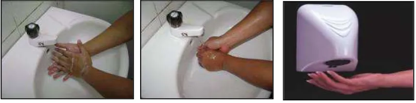
instruction from the sensor under the pipe and will activate valve for the water and the detergent. Lastly, the system will activate the dryer. It will function sequentially and automatically which helps to reduce the wastage of water and detergent. The figure below show the illustrated how the system plans to work by itself or automatically. This machine, which can bring peoples to a new era, that is modern and sophisticated. This is because this machine uses system which is 100% automatic. This machine can be used anywhere such as in restaurant, public toilet, resting area and others.
[image:22.595.124.553.254.361.2]1 2 3
Figure 1.1: 1) Automatic Dispense Detergent, 2) Rinsing stage, 3) Dryer
3
1.2 Project Objective
The objective of project is to make sure that the project following on the right plan and what the project really want to achieves. Besides than it also to ensure the positive progress of the development system and also to ensure that the main objective will be realized. Below are the objectives of the project:
§ To create new technology.
§ To get to know and learnt the operation of certain circuit such as the control circuit.
§ To create a product which have a commercial value. § To reduce the wastage of water and detergent.
§ Programmers Logic Control is equipment which is very useful and complicated. Getting a chance to use the equipment is an advantage and a great opportunity for us.
§ To simplify human life by upgrading the way of cleaning their hands hygienically.
1.3 Problem Statement
The usage of this product is to promote hygienic lifestyle especially for Malaysian citizen. Sometimes, people do not realize that they actually didn’t wash their hand properly and with this product help them to wash it properly. Besides that, it will produce new technology which will help prevent the wastage of water. Lastly, this product is efficient and easy to use for all users.
1.4 Scope of Work
4
1.4.1 Study and Research
Get as many as information about this project from books, internet, journal, and supervisor and also from products that sold at the market so that more knowledge can be known about this project. These findings also include the hardware and software that used to produce the project following the specification.
1.4.2 Design and construct the programming
PLC (Programmable Logic Controller) is used as a main controller. To program the PLC first the ladder diagram were designed using Grafcet Method then constructed and run the simulation using CX-Programmer.
1.4.3 Hardware Design and Equipments
The circuit designing and constructing process is done using P-Spice Software. P-Spice is a SPICE analog circuit and digital logic simulation software that runs on personal computers which help student to make sure the circuit run before it been transferred to PCB. Beside PLC, there is other particular devices use to produce this project such as valve (240V), liquid pump, and IR sensor (receiver and transmitter).
1.4.4 Finishing