City, University of London Institutional Repository
Citation
: Kim, S., Nouri, J. M., Yan, Y. & Arcoumanis, C. (2009). Effects of intake flow on
the spray structure of a multi-hole injector in a DISI engine. International Journal of
Automotive Technology, 10(3), doi: 10.1007/s12239-009-0032-2
This is the accepted version of the paper.
This version of the publication may differ from the final published
version.
Permanent repository link:
http://openaccess.city.ac.uk/14336/
Link to published version
: http://dx.doi.org/10.1007/s12239-009-0032-2
Copyright and reuse:
City Research Online aims to make research
outputs of City, University of London available to a wider audience.
Copyright and Moral Rights remain with the author(s) and/or copyright
holders. URLs from City Research Online may be freely distributed and
linked to.
City Research Online:
http://openaccess.city.ac.uk/
[email protected]
EFFECTS OF INTAKE FLOW ON THE SPRAY STRUCTURE
OF A MULTI-HOLE INJECTOR IN A DISI ENGINE
S. KIM
1)*, J. M. NOURI
2), Y. YAN
2)and C. ARCOUMANIS
2)1) Department of Automotive Mechanical Engineering, Silla University, Busan 617-736, Korea
2) School of Engineering and Mathematical Sciences, The City University, Northampton Square,
London, EC1V 0HB, UK
ABSTRACT−The spray characteristics of a 6-hole injector were examined in a single cylinder optical direct injection spark ignition engine. The effects of injection timing, in-cylinder charge motion, fuel injection pressure, and coolant temperature were investigated using the 2-dimensional Mie scattering technique. It was confirmed that the in-cylinder charge motion played a major role in the fuel spray distribution during the induction stroke while injection timing had to be carefully considered at high injection pressures during the compression stroke to prevent spray impingement on the piston.
KEY WORDS : Mie scattering, Intake swirl, Spray structure, Multi-hole injector, Direct injection, Gasoline engine
1. INTRODUCTION
Direct-injection spark ignition (DISI) engines offer the best promise for simultaneous reduction of fuel consumption and exhaust emissions in gasoline engines. Several DISI engine models have emerged into the international market and have highlighted the potential benefits on both fuel economy and pollutant reduction. Most of these engines are based on the wall-guided combustion design concept (Wirth et al., 1998; Nouri and Whitelaw, 2002). These “first generation” injection systems, with swirl pressure atomizers have been shown lower fuel consumption by up to 20% in the case of stratified, overall-lean part-load operation, but showed no significant improvements in HC and NOx emissions (Fraidl et al., 1996). The key success in DISI engines is in preparing the right amount of stratified fuel mixture under part-load operation when the fuel is injected late in the compression stroke; the goal is to quickly transport the fuel/air mixture towards the spark plug with no impingement on surfaces and to achieve complete evaporation of the droplets in the short time available between the end of injection and start of ignition.
Most recent studies have focused on an alternative strategy to the wall- and air-guided mode of mixture preparation for producing stratified fuel mixture preparation for producing stratified fuel mixtures, the so-called spray-guided using a new generation fuel injection system with either central or side fuel injection (Wirth et al., 2004; Shim et al., 2008). The major advantage of this configuration is that it makes use of the injection process to ensure that a stable combustible mixture reaches the spark plug at the time of ignition which, in turn, depends strongly on the spray characteristics and, in particular, its cycle-to-cycle stability which otherwise may even cause a misfire. Thus, to utilize the full benefit of DISI technology, knowledge of the temporal evolution of the spray structure, its tip penetration and distribution of the droplet velocities and diameters as a function of nozzle design, and injection and chamber pressures is a prerequisite. It should be mentioned that the swirl pressure atomiser (first generation) was found to be unsuitable for the new concept of mixture preparation due to demonstrated spray cone angle instability with back pressure, leading to a complete collapse of the spray structure when fuel was injected during the compression stroke (Li et al., 2004; Nouri and Whitelaw, 2006).
2006, 2007) regarding gasoline spray characteristics and mixture distribution. The constant high pressure chamber was equipped with a high-pressure multi-hole injector at injection and chamber pressures up to 20 MPa and 1.2 MPa, respectively. The test results in the constant chamber confirmed that the overall spray angle relative to the axis of the injector was independent of injection and chamber pressure. The effects of injection and chamber pressure on droplet velocities and diameter were also quantified. From the experimental results in the engine, for late fuel injection during the compression stroke, aiming at stratified overall lean mixtures, the elevated in-cylinder gas pressure/density reduces spray penetration and produces a more compact spray that can more easily be directed towards the spark plug. In addition, the investigations of (Birth et al., 2006; Nouri et al., 2007) identified the complex nature of the in-nozzle flow and, in particular, the development of different types of cavitation that can influence the stability of the emerging jet sprays.
Mixture preparation in direct injection engines is one of the most important processes in ensuring a successful DISI combustion system (Zhao et al., 1997). Preparing the desired mixture inside the combustion chamber over the full range of engine operating conditions is quite difficult, as the fuel/air mixing process is influenced by many time dependant variables. In this study, the spray characteristics generated by a high pressure multi-hole injector have been examined as a function of injection timing, in-cylinder air charge motion, coolant temperature, and injection pressure using the Mie scattering technique. The engine configuration and experimental techniques for the present experiments are described in the following section, the results are presented and discussed in section 3, and the paper ends with a summary of the most important findings.
2. EXPERIMENTAL SET-UP
2.1. Engine Design
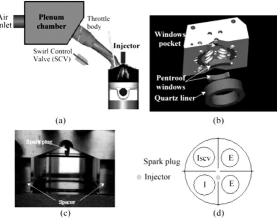
[image:3.595.157.443.488.713.2]The single cylinder research engine used in this study was designed for optical measurements and, as such, it offers good optical access. It includes a 4-valve modern pent roof cylinder head designed to allow spray guided operation. The optical engine set up is shown in Figure 1 (a)~(d), and the engine configuration details are summarized in Table 1. As shown in Figure 1(a), downstream of the throttle valve, there is a second valve installed at the inlet of one of the ports, named the Swirl Control Valve (SCV). When this valve is closed, in-cylinder swirl is generated. The position of this valve can be varied manually from fully open to closed using an external gauge controller. Without SCV, this cylinder head was designed to generate high tumble flows; and the TVRo (steady flow tumbling vortex) values measured were 1.38 for 1000 rpm in a steady flow rig test (Karaiskos, 2005).
Table 1. Test engine specifications.
Cylinder head Pent roof Ports Tumble/Swirl
Bore×Stroke (mm) 83 ×92 In. Vavle timing 6oBTDC/ 50oABDC
Compression ratio 10.5 Ex. Valve timing 50oBBDC/ 6oATDC
Optical access to the combustion chamber was provided from the side (vertical images) via a fused silica cylinder liner (Figure 1(b) and 1(c)). As shown in Figure 1(b), there are also two quartz windows on both sides of the cylinder head to provide access to the pent roof area. The piston crown has a flat design so that an optical window can be fitted to obtain horizontal images. The injector and spark plug are oriented longitudinally, as shown in Figure 1(d); the line of the spark plug and injector is in the middle of the pent roof, between the intake and exhaust valves. All tests were carried out without combustion, and with the engine being motored. Identification of the engine cycle and crank angle position was achieved by an optical pick up sensor mounted on the exhaust camshaft, and a crankshaft encoder (Muirhead Vactric), which produced 1440 pulses per revolution, thus resulting in a resolution of 0.25ºCA. Engine control was achieved by using an advanced timer card (NI PCI-6602) with in-house software (Labview), which controlled injection and ignition.
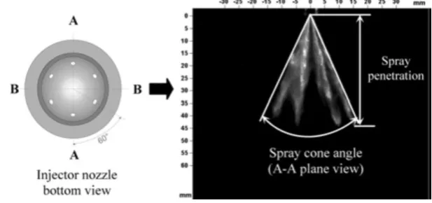
[image:4.595.140.449.457.602.2]The prototype injector used in the present experiments had been designed and manufactured by Bosch specifically for DISI engines, and it is a high pressure six hole injector with the holes symmetrically arranged on the periphery of an imaginary circle, as shown in Figure 2. The detailed specifications of the multi-hole injector, which operates with injection pressures up to 20 MPa, are described in Table 2. In view of the very short time available for fuel atomization and vaporization in DISI engines, particularly in the case of injection late in the compression stroke, the electromechanical response of the injector becomes an important consideration. Therefore, prior to the acquisition of spray images for the characterization of the spray development during the injection period, the injection delay, defined as the time between the rising edge of the triggering signal and first appearance of liquid at the nozzle exit, was quantified. Throughout preliminary injection testing, the injection delay time was found to be 0.7 ms, and during convenient spray image acquisition, the real injection delay time was adjusted to 0.2 ms with a 0.5 ms delay in the triggering signal.
Figure 2. Injector nozzle and spray view.
Table 2. Specifications of multi-hole injector.
Hole numbers 6 Cone angle 42o
Hole diameter 140 μm L/D ratio 2.14
Manufacturer BOSCH Production type Gasoline DISI
Proto type
2.2. Mie Scattering System
Qualitative and quantitative information about the spray was extracted from highresolution forward illuminated images recorded with a non-intensified 12 bit CCD PCO SensiCam camera, offering a resolution of 1024 ×1240 pixels and low readout noise, in conjunction with a Nikkor telescopic zoom lens (75~300 mm 1/4.5~5.6). Image acquisition timing is controlled by the engine control system, which is equipped with two general purpose triggers. An active cycle frequency of image acquisition and fuel injection was set in such a way as to allow sufficient time (15 s) for the xenon flash light to recharge fully.
To explore the spray pattern of a high pressure 6-hole injector, a variety of different operating modes and conditions were tested, as shown in Table 3. The injection duration was kept at 1 ms for all of the test conditions.
Table 3. Experimental conditions.
SCVposition Open/Close Injection pressure 7MPa/12MPa
Coolant temperature 40ºC/ 90ºC Fuel ISO Octane
Intake air temperature ~20ºC Operating mode Homogeneous/
Stratified
Spray imaging was repeated three times for each time step of each test case. The spray cone angle and penetration, obtained from the Mie images, are defined and provided in
Figure 2; images taken in the A-A plane view were used to obtain the spray cone angle. For the investigation of incylinder spray characteristics, the injected sprays of the 6- hole injector were visualized in the B-B plane view at engine speeds of 1000 rpm. There is a 0.2 ms delay between the injection trigger signal and first appearance of a spray. Therefore, spray evolution images were captured from 0.3 ms ASOI to 1.1 ms ASOI at 0.1 ms time intervals.
3. RESULT AND DISCUSSION
3.1. Early Injection for Homogeneous Stoichiometric Operation
Multi-hole injectors are known to have stable spray structures under various operating conditions. The overall spray cone angle remains close to the nominal design value with increasing chamber pressure; thus, early and late injection during an engine’s cycle appear to have almost identical spray shape, affecting only the spray’s penetration in the combustion chamber. Homogeneous operation dictates early injection of the fuel during the induction stroke. A selection of early injection timing includes injection of fuel at ATDC 60oCA, 90oCA, and 120oCA.
From the previous LDV measurement of in-cylinder flow under ‘SCV open’ or tumble flow condition
(Kariskos, 2005), it was realized that high velocities were generated during the intake process, rising to
a maximum between ATDC 60oCA and 120oCA, and then decreasing in response to the piston motion.
During this period, the incoming high velocity annular air-jet flows were directed axially towards the down-going piston and radially towards the exhaust. The results also showed that the generated swirl flow was neither strong nor well defined with respect to cylinder axis. The injected spray pattern during the intake stroke with ‘SCV open’ can be strongly affected by the tumble motion and its variation will result from the turbulence of the swirl motion.
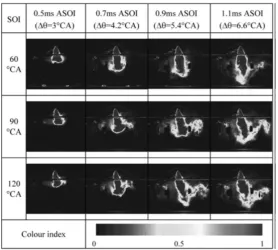
Evolution of the spray pattern at different injection timings of ATDC 60oCA, 90oCA, and 120oCA, with
the SCV fully closed (maximum swirl), a fuel injection pressure of 7 MPa, and a coolant temperature of
40oC is displayed in Figure 3. As shown, there are two distinct features in the spray structures; one is
start to be separated from the main plume jet towards the cross-flow direction; the latter effect may be a result of high swirling and turbulence. The extent of the separation increases with elapsed time after the start of injection, and those of ATDC 90oCA and 120oCA SOI are more pronounced than that of
[image:6.595.159.438.140.390.2]ATDC 60oCA.
Figure 3. Mie images during the intake stroke under swirl flow, Pinj.=7MPa, and Tcoolant=40ºC.
At 0.9~1.1 ms ASOI, the spray tilt is even more recognizable, with downstream injected fuel droplets largely distributed in the cross-flow direction. This phenomenon represents the promotion of the injected fuel distribution through the combustion chamber. The swirl flow activates the spatial advantage of the multi-hole nozzle to accommodate the homogeneous charge mixture. At 1.1 ms of elapsed time, a small portion of the separated fuel droplets reaches the cylinder wall, which is undesirable. The spray
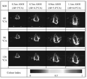
evolution with tumble flow, with a fuel injection pressure of 7 MPa and a coolant temperature of 40oC at
the start of injection at ATDC 60oCA, 90oCA, and 120oCA, is displayed in Figure 4. Similar to the spray
pattern under swirl flow, and for the same reasons, the multiple spray plumes cannot be distinguished. The injected fuel spray plumes cannot avoid the strong influence of the incoming air cross flow during intake valve opening due to the injector position in the cylinder head. Generally, the tumble flow does not deflect the spray pattern as strongly as the swirl flow, and there is no fuel droplet separation phenomenon; the latter indicates no impingement on the liner. The larger spray deflection and droplets separation with swirl flow, as seen in Figure 3, clearly suggest the presence of centrifugal force acting on the fuel droplets away from the centre of the cylinder. Overall comparison with the spray patterns under the flow of Figure 3 indicates that the spatial distribution of the injected fuel spray under tumble flow is apparently less than that of swirl flow, especially over the elapsed time of 0.7 ms. In addition, the tilt of the overall spray in the direction of the intake cross-flow is not as much as the swirl. Therefore, for a well distributed, homogenized and stoichiometric mixture, it is more important for swirl flow to be generated in the cylinder than tumble flow.
3.2. Late Injection for Stratified Lean Operation Mode
The concept of stratification needs to be clarified according to the engine design. At the time of ignition, an ignitable mixture cloud should be around the vicinity of the spark plug. This mixture cloud could be slightly rich in fuel locally, while the remaining volume of the combustion chamber is occupied by air. The size of the mixture cloud increases with increasing engine load, and the load is controlled quantitatively by the amount of fuel injection. The most common technique to achieve mixture stratification is by injecting the fuel during the compression stroke, and after the closure of the inlet valve. In this study, three injection timings during the compression stroke have been selected ATDC
270oCA, 285oCA, and 300oCA, which were defined as medium and late injection timings. During this
increased linearly across the cylinder while the weak main flow moved towards the exhaust valve area. These tumbling/swirl velocity values are much smaller than those of early induction, which may suggest that the injected spray pattern during the compression stroke may be less affected by the tumble motion. The evolution of the spray pattern at the start of injection at ATDC 270oCA, 285oCA, and 300oCA, with
the SCV fully closed (swirl), fuel injection pressure of 7 MPa, and coolant temperature of 40oC, is
displayed in Figure 5. Not like the spray pattern of the intake stroke, the multiple spray plumes from a multi-hole nozzle can clearly be discriminated. As mentioned before, the axial and swirl mean velocities, and also the turbulence level, were not so large as to overcome the spray plume momentum, and therefore there is much less deformation and dispersion of fuel droplets. Until an elapsed time of 0.9 ms ASOI, the spray plume patterns were similar regardless of SOI timing. However, when the elapsed time exceeds 0.9 ms ASOI, the front shape of the tip of spray plumes can no longer maintain its straight penetration, and is distorted slightly perhaps due to the RMS component of swirl flow. With respect to the start of injection timing, the growth of spray penetration is restricted by the upward moving piston
and higher chamber pressure. The spray penetration of ATDC 300oCA SOI was strongly affected, and
[image:7.595.157.440.267.525.2]a shorter spray penetration can be observed.
Figure 4. Mie images during the intake stroke under tumble flow, Pinj.=7MPa, and Tcoolant=40ºC.
The evolution of the spray pattern under conditions of tumble flow, fuel injection pressure of 7 MPa, and
coolant temperature of 40oC is displayed in Figure 6. Similar to the spray pattern under swirl flow, the
whole spray pattern was kept straight regardless of SOI. With respect to the start of injection timing, growth of the spray plumes maintains its straight penetration, unlike that of the swirl flow. From the spray pattern of late injection during the compression stroke, it can be argued that the spray shape and penetration were affected by the RMS component of in-cylinder flow and piston movement. In particular, the spray penetration of the latest start of injection is strongly restricted
by the upward moving piston.
3.3. Temperature Effect on Spray Droplet Vaporization
Figure 5. Mie images during the compression stroke under swirl flow, Pinj.= 7 MPa, and Tcoolant =40ºC.
Figure 6. Mie images during the compression stroke under tumble flow, Pinj.=7MPa, and Tcoolant=40ºC.
[image:8.595.150.442.600.751.2]Figure 8 illustrates the temperature effect on spray droplet vaporization for sprays injected at 7 MPa and 12 MPa into the cylinder. In general, the results show that a small amount of liquid fuel is vaporized for a temperature rise from 40oC to 90oC, this is perhaps expected since the boiling temperature of the
fuel (isooctane) is 102o~105oC @0.1 MPa; similar results was reported (Mitroglou, 2005) for the same
increase in temperature. It is also evident that the amount of vaporize fuel is slightly more with higher injection pressure probably due to minor improvements in atomization and efficacy. A more specific analysis is needed to quantify the effect of a coolant temperature of 90oC in spray vaporization relative
to 40oC. For example, taking plane Mie images rather than surface images will help considerably, along
with taking extra images at temperatures above the fuel boiling point. Overall, the present results show that only small amounts of liquid are expected to vaporize during the injection, and this would most likely happen around the edges of the individual fuel spray jets, away from the injector exit.
Figure 8. Effect of the coolant temperature on fuel vaporization at ATDC 300°CA SOI under tumble flow.
3.4. Spray Penetration and Cone Angle
The spray penetration and spray cone angle at different injection timing, injection pressure, and coolant
temperature at 1000 rpm are plotted in Figure 9 and Figure 10. The spray penetration of 60oCA SOI
and Tcoolant=40oC is shown in Figure 9(a). The penetration is affected by fuel injectionpressure so that at
[image:9.595.86.513.585.704.2]initial stage till 0.5 ms ASOI, the spray penetration at 7 MPa is a little greater than that of 12 MPa, mainly because the mechanical operational delay time of the injector at 12 MPa is longer. However, the injected fuel droplets had a substantial momentum, as a result of the higher fuel pressure, and consequently, penetrated further into the cylinder than those injected at a lower injection pressure as the time ASOI increases.
Figure 9. Spray penetration during intake and compression strokes.
From the elapsed time of 0.6 ms ASOI, the spray penetration at 12 MPa becomes greater than that at 7 MPa. The penetration continues to increase until 0.8 ms ASOI, and from 0.8 ms ASOI onward, the
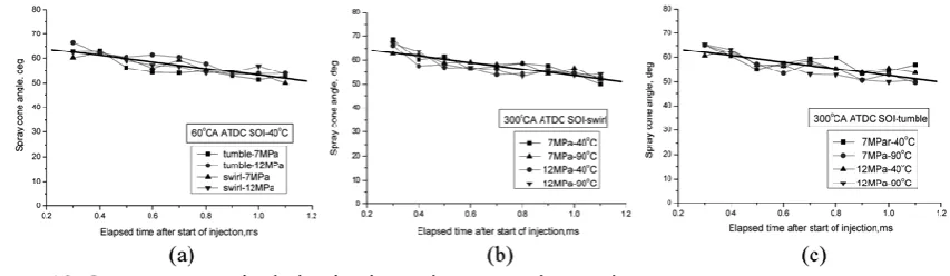
SOI under swirl and tumble flow are shown in Figure 9(b) and Figure 9(c), respectively. The spray penetration during the compression stroke has a similar trend to that of the intake stroke. The penetration is also affected by fuel injection pressure. But additionally, it is strongly affected by the chamber pressure (moving piston), which causes a maximum penetration of 35 mm, shorter than that of the intake stroke. After 0.9~1.0 ms ASOI, the spray tip starts to impinge on the piston. The injected fuel of high pressure reaches the piston earlier than that of lower pressure. Therefore, it is necessary to carefully consider the extent of fuel impingement according to the fuel pressure. But, the temperature effect on the spray penetration is small and not as noticeable as the fuel pressure. The plane (A-A), where the overall spray angle was calculated, is shown in Figure 2, and the angle was measured between the extreme edges of the two outer jet sprays near the injector tip, where the effects of the cross-flow was minimum. Figure 10 shows the spray cone angle during intake and compression stroke, and at different injection pressures and coolant temperatures.
Figure 10. Spray cone angle during intake and compression strokes.
The results showed that the overall spray angle remained constant and almost independent of injection pressure, chamber pressure, and coolant temperature. There is also a small and gradual reduction in the overall spray cone angle with the elapsed time ASOI, which is similar for all conditions tested, making the overall spray cone angle smaller than that of the nominal value. This can be related to the complex flow structure inside the nozzle hole, especially in the presence of different types of cavitation, depending on pressure differences across the nozzle due to the opening of the needle. In particular, there is a geometric cavitation that forms on the upper part of the nozzle, and can affect the trajectory of the exiting fuel jets by forcing them downwards.
4. CONCLUSION
Spray characteristics of a high pressure 6-hole multi-hole injector were investigated in an optical engine using Mie scattering. The results were obtained at an engine speed of
1000 rpm, and the effects of injection timing, in-cylinder charge motion, coolant temperature, and injected fuel pressure were investigated. The most important findings are summarized below:
(1) To obtain a homogeneous and stoichiometric mixture, in-cylinder swirl proved to be far more effective than tumble flow during the intake stroke. The results showed a clear shift of the spray jets in the direction of the intake cross-flow.
(2) The spray pattern of late injection during the compression stroke was little affected by tumble and swirl cross-flow. However, the effect of increased chamber pressure due to piston movement was considerable in limiting the spray jet penetration.
(3) The effect of coolant temperature on fuel droplets vaporization was found to be small when the temperature was raised from 40oC to 90oC.
(4) Fuel pressure promotes spray penetration although, during the compression stroke, it is strongly affected by the upward moving piston causing an increase in the air density in the cylinder. (5) The overall spray cone angle was found to be constant and almost independent of injection
pressure, chamber pressure, and coolant temperature. A gradual reduction in the overall spray angle was also found with elapsed time after the start of injection, which can be related to the development of cavitation in the nozzle holes.
REFERENCES
Birth, I. G., M. Rechs, M. U., Spicher, U. and S. Bernhardt, S. (2006). Experimental investigation of the in-nozzle flow of valve covered orifice nozzle for gasoline direct injection. 7th Int. Symp. Internal Combustion Diagnostics, 59−78, Kurhaus Baden-Baden.
Fraidl, G. K., Piock, W. F. and Wirth, M. (1996). Gasoline direct injection. actual trends and future strategies for injection and combustion systems. SAE Paper No. 960465, 95− 111.
Honda, T., Kawamoto, M., Katashiba, H., Sumida, M., Fukutomi, M. and Kawajiri, K. (2004). A study of mixture formation and combustion for spray guided DISI. SAE Paper No. 2004-01-0046.
Karaiskos, I. E. (2005). Spray Structure and Mixture Distribution in a Direct Injection Gasoline Engine. Ph. D. Dissertation, University of London.
Li, T., Nishida, K. and Hiroyasu, H. (2004). Characterization of initial spray from a D.I. gasoline injector by holography and laser diffraction method. Int. J. Atomization and Sprays, 14, 477−494.
Lippert, A. M., El Tahry, S., Huebler, M. S., Parrish, S. E., Inoue, H., Noyori, T., Nakama, K. and Abe, T. (2004). Development and optimisation of a small-displacement spark-ignition direct-injection engine-stratified operation. SAE Paper No. 2004-01-0033.
Mitroglou, N. (2005). Multi-Hole Injectors for Direct- Injection Gasoline Engines. Ph. D. Dissertation. The City University.
Mitroglou, N., Arcoumanis, C., Mori, K. and Motoyama, Y. (2005). Mixture distribution in a multi-valve twinspark ignition engine equipped with high-pressure multihole injectors. ICOLAD 2005, 27−40. Mitroglou, N., Nouri, J. M., Gavaises, M. and Arcoumanis, C. (2006). Flow and spray caracteristics in
spray-guided direct injection engines. J. Engine Research 7, 3, 255− 270.
Mitroglou, N., Nouri, J. M., Yan, Y., Gavaises, M. and Arcoumanis, C. (2007). Spray structure generated by multi-hole injectors for gasoline direct injection engines. SAE Paper No. 2007-01-1417.
Nouri, J. M. and Whitelaw, J. H. (2002). Effect of chamber pressure on the spray structure froma swirl pressure atomiser for direct injection gasoline engines. 1st Int. Conf. Optical Diagnostics, ICOLAD, 1, 121−129.
Nouri, J. M. and Whitelaw, J. H. (2006). Impingement of gasoline sprays on angled plates. Int. J. Atomization and Sprays 16, 6, 705−726.
Nouri, J. M., Mitroglou, N., Yan, Y. and Arcoumanis, C.
(2007). Internal flow and cavitation in a multi-hole injector for gasoline direct injection engines. SAE Paper No. 2007-01-1405.
Nouri, J. M. and Whitelaw, J. H. (2007). Impingement of gasoline sprays on angled plates. Int. J. Atomization and Sprays 17, 6, 1−20.
Ortmann, R., Arndt, S., Raimann, J., Grzeszik, R. and Wurfel, G. (2001). Methods and analysis of fuel injection, mixture preparation and charge stratification in different direct-injected SI engines. SAE Paper No. 2001-01-0970.
Preussner, C., Doring, Fehler, S. and Kampmann, S. (1998). GDI: interaction between mixture preparation combustion system, and injector performacne. SAE Paper No. 980498.
Shim, Y. S., Choi, G. M. and Kim, D. J. (2008). Numerical modeling of hollow-cone fuel atomization, vaporization and wall impingement processes under high ambient temperatures. Int. J. Aumotive Technology 9, 3, 267− 275.
Skosberg, M., Dahlander, P., Lindgren, R. and Denbratt, I. (2005). Effects of injector parameters on mixture formation for multi-hole nozzles in a spray-guided gasoline DI engine. SAE Paper No. 2005-01-0097.
Wirth, M., Piock, W. F., Fraidl, G. K. K., Schoeggi, P. and Winklhofer, E. (1998). Gasoline DI engines. The complete system approach by interaction of advanced development tools. SAE Paper No. 980492.
Wirth, M., Zimmermann, D., Friedfeldt, R., Caine, J., Schamel, A., Davies, M., Peirce, G., Storch, A., Ries-Müller, K., Gansert, K. P., Pilgram, G., Ortmann, R., Würfel, G. and Gerhardt, J. (2004). A cost optimised gasoline spray guided direct injection system for improved fuel economy, seminar on fuel economy and engine downsizing. Institution of Mechanical Engineers, One Birdcage Walk, London, 13 May 2004.