IAC-14-C1.6.11
ANALYTICAL THREE-PHASE TRANSFER TO A SOLAR POLAR ORBIT USING SOLAR SAIL PROPULSION
Ciara McGrath
University of Strathclyde, United Kingdom, [email protected] Malcolm Macdonald
University of Strathclyde, United Kingdom, [email protected]
A general solution for a 3-phase transfer trajectory from the Earth to a solar polar orbit using solar sail propulsion is presented, deriving for the first time the optimal trajectory architecture without the need for engineering assumptions and numerical analysis. The 3-phase transfer presented involves spiralling in close to the Sun, performing a rapid inclination increase, and spiralling back out to the final target orbit. The general perturbation solution allows the split of inclination change per phase to be optimised for the minimum transfer duration, negating the need for assumptions used in previous numerical optimisations. This method offers significant advantages over the numerically optimised solutions currently available as it allows for a complete understanding of the optimal structure of the trajectory to be gained. These results show that the 3-phase transfer can offer time savings of approximately 30% when compared with a 2-phase transfer. By further sub-dividing the spiral phases into shorter sections it is found that it is possible to further optimise the trajectory; this approach could theoretically be extended to approximate an optimal transfer trajectory. The simplest of these extensions, the 5-phase transfer, is found to offer only a 1% time saving compared with the 3-phase transfer, suggesting that further optimisation beyond the 3-phase transfer may yield only minor improvements. Comparison with existing numerical solutions shows the general perturbation solution to offer a 10% reduction in transfer time due to the optimisation of the amount of inclination change per phase. Thus, this analytical description of the time-optimal transfer trajectories for a mission to a solar polar orbit offers significant advantages for system design trade studies and future mission design.
I. INTRODUCTION
Scientific missions to observe the solar poles have been proposed since the 1970s1 but have yet to be achieved with the exception of Ulysses, which necessitated long revisit times and took no visual images of the solar poles. Solar Orbiter, due to launch in 2017, will allow space based observations only within ± 36° of the solar equator due to the high change in velocity required to increase inclination. The use of solar sail propulsion overcomes this difficulty2.
Previous general perturbations studies have proposed the use of a 2-phase transfer to reach a solar polar orbit. This consists of an initial phase to reduce the semi-major axis to the target value and a second phase in which the inclination is rapidly increased3. However, it has been identified that using a 3-phase transfer, which involves spiralling in close to the Sun, performing a rapid inclination increase, and spiralling back out to the final target orbit, may offer time savings over the 2-phase approach4.
This paper uses a general perturbation solution to describe the optimal trajectory for a 3-phase transfer from the Earth to a solar polar orbit using solar sail propulsion. Numerically optimized solutions for the 3-phase transfer are available5 however they do not allow
for a complete understanding of the optimal structure of the trajectory to be gained.
A general perturbation solution has previously been derived for the 2-phase transfer. This solution can be analytically solved and has been used to define feasible transfer trajectories for a solar polar mission6. By extending this work to include the 3-phase transfer option, feasible trajectory architectures with significantly reduced transfer times can be identified. Further, by breaking each transfer phase into smaller increments it is possible to approximate an optimal control law for the out-of-plane thrust vector during the transfer.
II. TRAJECTORY DEFINITION
phase involves spiralling out to the target orbit of semi-major axis
a
2 and inclinationi
3.The transfer trajectory can be described using general perturbation approximation equations for solar sail propulsion7 and extending them to describe a 3-phase transfer. These are derived from the Lagrange-Gauss variational equations adapted for a spiral transfer using a solar sail. From these, the transfer time for a spiral transfer in which the semi-major axis is reduced or increased can be described by
3 3
2 2
1 0
2
3
sin
cos (cos
)
spiral
a
a
t
[1]where the ‘±’ indicates a positive or negative rate of change of semi-major axis respectively. That is, for a decrease in semi-major axis the negative term is used, and for an increase in semi-major axis the positive term is used.
If an inclination change occurs during the spiral manoeuvre, the resultant orbit inclination is given by
3 2 2 0 0 3 2 2 0
3 csc sec (sec )
2 tan ln
3 csc sec (sec )
spiral spiral t a i i a [2]
where again ‘±’ indicates a positive or negative rate of change of semi-major axis respectively.
For the transfer phase in which the inclination is varied while maintaining a constant semi-major axis, also known as the ‘cranking’ phase, the transfer time is given as
3
2 2
1 1 2
csc (sec
)
2
crank
a
i
i
t
[3]where the ‘±’ term here represents a negative or positive rate of change of inclination respectively. That is, for an increase in inclination the negative term is used, and for a decrease in inclination the positive term is used.
Summing up the transfer time required for each transfer phase, and subbing for the inclination change occurring during the spiral manoeuvre using equation [2], can give the total transfer time for the 3-phase manoeuvre expressed in terms of the sail lightness number β, the semi-major axis a at each transition point, the augmented sail clock angle γ for each manoeuvre phase, the initial and final inclinations i, the gravitational constant for the central body µ, and the sail pitch angle α. The sail lightness number, augmented sail clock angle and sail pitch angle here are all as
previously defined by Macdonald8. This can be written in the form,
3 2 2 1 3
1
1
[
cos
cos
1
t
a
A
B
3 2 2 3 3 2
1 3 1
3 2 1
1
1
{
log[
] tan
}
cos
c s
(
o
a
a
a
B
3 23
tan
1(
log[
1]
))]
i
a
C
B
D
[4]where
A
,B
,C
andD
are all constants determined by the orbit parameters.Multi-Phase Transfers
By breaking the two spiral phases of the 3-phase trajectory into smaller sub-phases it is theoretically possible to adapt the general perturbation solution to approximate a fully optimal control law for the out-of-plane thrust vector during the transfer. The simplest of these adaptations is a 5-phase transfer which consists of two spiralling manoeuvres towards the Sun, each with a different sail angle, a rapid inclination change in the cranking orbit, and two spiralling manoeuvres away from the Sun, again each with a different sail angle. An expression describing the 5-phase trajectory can be derived in a similar manner as for the 3-phase trajectory.
III. GENERAL APPROACH
Due to the number of variables in equation [4] the 3-phase trajectory general perturbation solution cannot be analytically solved. The same is true for the multi-phase transfers described. However, using a constrained non-linear optimisation, with constraints set on the minimum cranking and target orbit semi-major axes, it is possible to solve the general perturbation solution to determine the combination of variables which will provide the minimum total transfer time.
To validate this optimisation approach, a 2-phase transfer was initially investigated. The results produced were identical to the analytical solutions found by Macdonald9 and confirm the validity of the approach used here to find an optimal solution.
IV. RESULTS
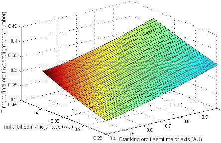
The minimum total transfer time required for a variety of cranking and final orbit semi-major axes is shown in Fig. 1. This demonstrates that, as would be expected, the smaller the cranking and target orbits, the shorter the time required to carry out the transfer. The time here is expressed in terms of the lightness number, demonstrating that these results are independent of the solar sail and spacecraft properties.
Knowing that for the 3-phase transfer the total transfer time is at a minimum when the semi-major axes of the cranking and target orbits are minimised, by defining the cranking and target semi-major axes,
a
1 anda
2 respectively, and the target inclinationi
3, then the sail angle for the first and third transfer phases,
1 and
3, can be plotted against the total transfer time. This is shown in Fig. 2 and Fig. 3 for a solar sail with a characteristic acceleration of 0.2 mm/s2 (lightness number, β = 0.03372). The values for the figures shown are selected assuming a transfer from a 1AU circular orbit within the ecliptic plane, to a cranking orbit at 0.25AU, and ending in a 0.4AU orbit of the Sun at an inclination of 82.75°. It also assumes1
1
tan
2
[5]for the locally optimal rate of change of semi-major axis10.
[image:3.612.316.538.71.215.2]From Fig. 2 it can be seen that, in general, the total transfer time increases as the sail angle in the first phase increases. That is, in general, the greater the amount of inclination change performed in the first phase, the slower the transfer will be. However, looking at a zoomed in region of the same graph as shown in Fig. 3, it can be seen that the shortest transfer time does not occur when
1= 0, instead there is a defined point at which the time is minimised, corresponding to a small sail angle in the first phase. There is likewise a specific value for
3which will give the shortest time. This means that for defined target and cranking orbits, a combination of sail angles can be identified for which the trip time is minimised. [image:3.612.317.541.260.429.2] [image:3.612.318.535.497.656.2]Fig. 1: 3-Phase Minimum transfer time for a range of cranking orbits and target orbits
Fig. 2: Total transfer time versus sail angle for the first and third phases with
a
1=0.25AU,a
2=0.4AU,i
3=82.75°
Fig. 3: Close up view of total transfer time versus sail angle for the first and third phases with
a
1=0.25AU,2
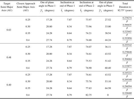
Table 1 details the optimal general perturbations solutions for transfers from a circular 1AU orbit within the ecliptic plane to an 82.75° inclined, circular orbit at a range of target solar radii, and for a variety of cranking orbit semi-major axes. By comparing these results with existing analyses11 it can be shown that the 3-phase transfer offers a time saving of approximately 30% when compared with the 2-phase transfer. In all cases the inclination at the end of the first phase is typically between 7 – 9 degrees, and at the end of the second phase is typically between 74 – 83 degrees. The out-of-plane angle in Phase 1,
1, ranges from 17 – 28 degrees whilst in Phase 3,
3, ranges from 27 – 44 degrees.It is of note that the sail angle in the first phase and the inclination at the end of the first phase,
1 andi
1, are dependent only on the cranking orbit radius and are independent of the target orbit parameters. In addition, both values increase as the semi-major axis of the cranking orbit increases, meaning that a greaterpercentage of the inclination change is performed in Phase 2 as the cranking orbit approaches the Sun. The inclination at the end of the second phase, as well as the sail angle in the third phase,
i
2 and
3, are dependent on the parameters of both the cranking and target orbits and both are seen to increase as the semi-major axes of both relevant orbits increase.5-Phase Transfer
The results of the optimisation of the 5-phase transfer are shown in Fig. 4 where the minimum total transfer time required for the 5-phase trajectory is plotted for a range of cranking and final orbit semi-major axes. This is done again in terms of the lightness number of the solar sail and assumes a transfer from a 1AU circular orbit within the ecliptic plane, to a final orbit with an inclination of 82.75°. It also assumes the same value of α as in the 3-phase case. As in the case of the 3-phase transfer, the minimum transfer time occurs when the target and cranking orbit semi-major axes are minimised.
Target Semi-Major
Axis (AU)
Closest Approach Semi-Major Axis
(AU)
Out-of-plane angle in Phase 1
1
(degrees)Inclination at end of Phase 1
1
i
(degrees)Inclination at end of Phase 2
2
i
(degrees)Out-of-plane angle in Phase 3
3
(degrees)Total Duration to 82.75° (years)
0.63
0.25 17.28 7.87 73.97 27.52 0.278274
0.30 20.80 8.34 73.96 33.00 0.300639
0.35 24.28 8.64 74.21 38.54 0.325463
0.4 27.74 8.79 74.68 44.24 0.352856
0.48
0.25 17.28 7.87 74.07 36.11 0.255542
0.30 20.80 8.34 74.61 43.52 0.278646
0.35 24.28 8.64 75.53 51.42 0.304664
0.4 27.74 8.79 76.90 60.40 0.333877
0.40
0.25 17.28 7.87 74.61 43.52 0.245221
0.30 20.80 8.34 75.76 53.10 0.269168
0.35 24.28 8.64 77.63 64.58 0.296594
[image:4.612.69.538.351.697.2]0.4 27.74 8.79 82.75 0 0.328460
In the case of the 5-phase transfer the increased number of variables means that even defining the cranking and target orbit radii and the final inclination does not allow for an analytical solution to be derived. However, using the constrained non-linear optimisation approach, with constraints set on the minimum cranking and target orbit semi-major axes, it is possible to determine the sail angle required in each phase to give the minimum transfer time, as well as the optimal point at which the sub-phase division should occur in phases 1 and 3.
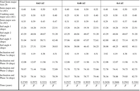
Table 2 details the optimal general perturbations solutions for a 5-phase transfer from a circular 1AU orbit within the ecliptic plane to an 82.75°, circular orbit at a range of target solar radii, and for a variety of cranking orbit semi-major axes. For the cases considered the resulting inclination at the end of Phase 1a ranges from 3° - 5°, and at the end of Phase 1b ranges from 11° - 13°. At the end of the cranking phase, Phase 2, the inclination value ranges from 70° - 77°, and the inclination at the end of Phase 3a ranges from 78° - 80°.
The general trend seen in the results suggests that an optimal trajectory would gradually increase the sail angle during solar approach and decrease this angle during the outwards spiral. This results in a gradual
inclination increase through all spiral phases, with the majority of the inclination change taking place close to the Sun.
[image:5.612.320.537.199.344.2]Further increasing the number of sub-phases should approximate an optimal trajectory and allow the transfer time to be further reduced. However, the results in Table 2 show that the 5-phase transfer offers a time saving of only 1% when compared with the 3-phase transfer suggesting that further trajectory optimisation may produce only limited time savings.
Fig. 4: 5-Phase minimum transfer time for a range of cranking orbits and target orbits
Final Semi-major
Axis 2b 0.63 AU 0.48 AU 0.4 AU
Semi-major axis
1a (AU) 0.40 0.46 0.50 0.55 0.40 0.46 0.50 0.55 0.40 0.46 0.50 0.55
Cranking
semi-major axis (AU) 0.25 0.30 0.35 0.40 0.25 0.30 0.35 0.40 0.25 0.30 0.35 0.40 Semi-major axis
2a (AU) 0.35 0.39 0.43 0.47 0.31 0.35 0.39 0.43 0.29 0.33 0.37 0.40
Sail angle 1
(degs) 13.26 16.26 19.34 22.51 13.26 16.26 19.34 22.51 13.26 16.26 19.34 22.51 Sail angle 2
(degs) 43.29 46.04 48.67 51.20 43.29 46.04 48.67 51.20 43.29 46.04 48.67 51.20 Sail angle 3
(degs) 51.04 54.93 58.71 62.48 57.06 62.00 67.07 72.61 62.00 68.12 75.14 82.75 Sail angle 4
(degs) 22.31 27.51 32.99 38.83 30.56 38.08 46.43 56.25 38.08 48.25 60.92 40.11 Inclination end
Phase 1a (degs) 3.92 4.19 4.38 4.51 3.92 4.19 4.38 4.51 3.92 4.19 4.38 4.51 Inclination end
Phase 1b (degs) 12.08 12.07 11.96 11.76 12.08 12.07 11.96 11.76 12.08 12.07 11.96 11.76 Inclination end
Phase 2 (degs) 70.97 71.44 72.08 72.89 71.78 72.78 74.10 75.86 72.78 74.41 76.75 82.75 Inclination end
Phase 3a (degs) 78.25 78.16 78.21 78.39 78.17 78.36 78.77 79.46 78.36 78.88 79.85 82.75
Time (years)
0.2749
0.2972
0.3221
0.3497
0.2527
0.2758
0.3019
0.3313
0.2426
0.2666
0.2941
0.3261
[image:5.612.71.546.387.698.2]
IV. COMPARISON WITH NUMERICALLY OPTIMISED TRAJECTORIES
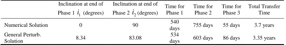
A 3-phase transfer to a solar polar orbit has previously been proposed and analysed by Leipold12. His analysis assumed the use of a solar sail with a characteristic acceleration of 0.5mm/ s2 (β=0.08432). The trajectory involved initially spiralling to an orbit with a semi-major axis of 0.3AU while maintaining a constant inclination, cranking the orbit up to 90° while maintaining a constant semi-major axis, and finally spiralling back out to a final orbit of 0.3968AU.
The results of Leipold’s analysis are shown in Table 3 where they are compared with a general perturbation solution for the same trajectory. The key difference between the two solutions is that the general perturbation solution includes a modest plane change manoeuvre in both the first and third phases. This greatly reduces the length of time required to be spent in the cranking phase and reduces the overall transfer time by approximately 3.5 months or 10% of the total time. This is a significant improvement over the numerical solution presented.
V. CONCLUSION
The general perturbation solution for a multi-phase transfer to a solar polar orbit is shown to be both feasible and practical. The nature of the solution allows the trajectory to be defined in terms of system parameters, allowing for straightforward mission and
system trades, and thus offers significant advantages over a numerically optimised solution with regard to mission design and planning.
The use of the 3-phase transfer is shown to offer a time reduction of approximately 30% compared with the 2-phase transfer and as such is an attractive option for a mission requiring a polar orbit of the Sun. Further sub-division of the phases was shown to be possible and could theoretically approximate an optimal control law for the sail angle throughout the transfer. However, the use of the 5-phase transfer offers less than a 1% time reduction when compared with the 3-phase transfer, suggesting that the use of a fully optimal control law during the first and third phases may offer only a modest reduction in the overall transfer time. This is encouraging as a 3-phase transfer, with a fixed sail angle for each phase, is a more feasible option in terms of spacecraft operations.
When compared with existing numerically optimised trajectories, the general perturbation solution is found to offer a time saving of almost 10%. This is a significant improvement which highlights the advantages of this approach and is due to the implementation of moderate plane change manoeuvers in both the first and third phases. The general perturbations approach here can thus be shown to offer significant advantages in terms of trajectory architecture design as well as for system design trade studies and future mission design.
Inclination at end of
Phase 1
i
1 (degrees)Inclination at end of
Phase 2
i
2(degrees)Time for Phase 1
Time for Phase 2
Time for Phase 3
Total Transfer Time
Numerical Solution 0 90 540
days 755 days 55 days 3.7 years General Perturb.
Solution 8.34 83.08
534
[image:6.612.64.528.474.547.2]days 603 days 86 days 3.35 years
REFERENCES
1
Bohlin, J.D “Advanced Solar Space Missions,” 17th Aerospace Sciences Meeting Jan. 1979.
2 Goldstein, B., Buffington, A., Cummings, A., Fisher, R., Jackson, B., Liewer, P., Mewaldt, R. and Neugebauer, M. “A Solar
Polar Sail Mission: Report of a Study to Put a Scientific Spacecraft in a Circular Polar Orbit about the Sun,” Proceedings of MTG: SPIE International Symposium on Optical Science, Engineering and Instrumentation, July 1998.
3
Macdonald, M. “Analytical, circle-to-circle low-thrust transfer trajectories with plane change”.AIAA Guidance, Navigation and Control Conference 2013, Boston, Massachusetts, 2013.
4
Macdonald, M., Hughes, G.W., McInnes, C.R., Lyngvi, A., Falkner, P., Atzei, A. “Solar polar orbiter: a solar sail technology reference study”, Journal of Spacecraft and Rockets, Vol. 43 No. 5, pp. 960-972, 2006.
5
Macdonald, M., Hughes, G.W., McInnes, C.R., Lyngvi, A., Falkner, P., Atzei, A. “Solar polar orbiter: a solar sail technology reference study”, Journal of Spacecraft and Rockets, Vol. 43 No. 5, pp. 960-972, 2006.
6
Macdonald, M. “Analytical, circle-to-circle low-thrust transfer trajectories with plane change,” AIAA Guidance, Navigation and Control Conference Aug. 2013.
7
Macdonald, M. “Analytical, circle-to-circle low-thrust transfer trajectories with plane change”.AIAA Guidance, Navigation and Control Conference 2013, Boston, Massachusetts, 2013.
8
Macdonald, M. “Analytical, circle-to-circle low-thrust transfer trajectories with plane change”.AIAA Guidance, Navigation and Control Conference 2013, Boston, Massachusetts, 2013.
Macdonald, M. “Analytical, circle-to-circle low-thrust transfer trajectories with plane change”.AIAA Guidance, Navigation and Control Conference 2013, Boston, Massachusetts, 2013.
10 Macdonald, M. “Analytical, circle-to-circle low-thrust transfer trajectories with plane change”.AIAA Guidance, Navigation
and Control Conference 2013, Boston, Massachusetts, 2013. 11
Macdonald, M. “Analytical, circle-to-circle low-thrust transfer trajectories with plane change”.AIAA Guidance, Navigation and Control Conference 2013, Boston, Massachusetts, 2013.
12 Leipold, M., “Solar Sail Mission Design,” Ph.D. Dissertation, DLR German Aerospace Center, Cologne, Germany, Feb.