Elsevier Editorial System(tm) for Robotics and Computer Integrated Manufacturing Manuscript Draft
Manuscript Number: RCIM-D-09-00078R1
Title: An Assembly-Oriented Design Framework for Product Structure Engineering and Assembly Sequence Planning
Article Type: Research Paper
Keywords: Assembly-Oriented Design, Design for Assembly, Product Structure, Assembly Process Planning.
Corresponding Author: Mister Frédéric Demoly, Ph.D. Student
Corresponding Author's Institution: Mechatronics, Methods, Models and Skills Laboratory - M3M, Université de Technologie de Belfort-Montbéliard
First Author: Frédéric Demoly, Engineer
Order of Authors: Frédéric Demoly, Engineer; Xiu-Tian Yan, Ph.D.; Benoît Eynard, Ph.D.; Louis Rivest, Ph.D.; Samuel Gomes, Ph.D.
Abstract: The paper describes a novel framework for an Assembly-Oriented Design (AOD) approach as a new functional part of the Product Lifecycle Management (PLM) strategy, by considering product design and assembly sequence planning phases concurrently. Integration issues of product lifecycle into the product development process have received much attention over the last two decades, especially at the detailed design stage. The main objective of the research is to define assembly sequence into preliminary design stages by introducing and applying assembly process knowledge in order to provide an assembly context for the product development process, particularly for product structuring. The proposed framework highlights a novel algorithm based on a mathematical model integrating boundary conditions related to DFA rules, engineering decisions for assembly sequence and the product structure definition. This framework has been implemented in a new system called PEGASUS considered as an AOD module for a PLM system. A case study of applying the framework to a Catalytic-Converter and Diesel Particulate Filter sub-system, belonging to an exhaust system from an industrial automotive supplier, is introduced to illustrate the efficiency of the proposed AOD
Cover Letter
Dear Editor of the Robotics and Computer-Integrated Manufacturing Journal,
Enclosed is a paper, entitled “
Assembly-Oriented Design Framework for Product Structure
Engineering and Assembly Sequence Planning
”. Please accept it as a candidate for publication
in the Robotics and Computer-Integrated Manufacturing Journal. Below are our responses to
your submission requirements:
Corresponding author:
Frédéric Demoly
Mechatronics, Methods, Models, and Skills Laboratory
Université de Technologie de Belfort-Montbéliard
90010 Belfort Cedex, France
Tel: +33 (0)3 84 58 37 50
Fax: +33 (0)3 84 58 32 07
[email protected]
Regarding the option of nominating up to three reviewers, our three nominees are:
Dimitris Kiritsis
Laboratory of Computer-Aided Design and Production (STI-IPR-LICP) Swiss Federal Institute of Technology in Lausanne (EPFL)
Station9, ME B1 344, CH-1015 Lausanne, Switzerland
Lionel Roucoules
Team IMSEcole Nationale Supérieure d’Arts et Métiers (ENSAM) CER d’Aix-en-Provence
2 cours des Arts et Métiers, 13617 Aix-en-Provence, France
Chris Paredis
The George W.Woodruff School of Mechanical Engineering Georgia Institute of Technology
Atlanta, GA, USA
The work described has not been submitted elsewhere for publication, in whole or in
part, and all the authors listed have approved the manuscript that is enclosed.
An Assembly-Oriented Design Framework for
Product Structure Engineering and Assembly Sequence Planning
_______________________________________________________________________________________________
Abstract:
The paper describes a novel framework for an Assembly-Oriented Design (AOD) approach as a new functional part of the Product Lifecycle Management (PLM) strategy, by considering product design and assembly sequence planning phases concurrently. Integration issues of product lifecycle into the product development process have received much attention over the last two decades, especially at the detailed design stage. The main objective of the research is to define assembly sequence into preliminary design stages by introducing and applying assembly process knowledge in order to provide an assembly context for the product development process, particularly for product structuring. The proposed framework highlights a novel algorithm based on a mathematical model integrating boundary conditions related to DFA rules, engineering decisions for assembly sequence and the product structure definition. This framework has been implemented in a new system called PEGASUS considered as an AOD module for a PLM system. A case study of applying the framework to a Catalytic-Converter and Diesel Particulate Filter sub-system, belonging to an exhaust system from an industrial automotive supplier, is introduced to illustrate the efficiency of the proposed AOD methodology.
Keywords: Assembly-Oriented Design, Design for Assembly, Product Structure, Assembly Sequence Planning.
___________________________________________________________________________________________________________________________________________
1. Introduction
The current ultra-competitive market in terms of Quality-Cost-Time coupled with the global financial crisis leads companies to set up research and development strategies in order to improve their competitiveness. Companies in the automotive industries are particularly facing their own industry-sector specific re-organization by bringing geographically distributed teams and expertise networks closer. Thus, the current industrial need requires the tackling of the traditional sequential engineering phases by taking concurrent engineering approach to overlapping lifecycle engineering activities. Indeed, the inclusion and integration of product lifecycle activities into the product development process have received much attention over the last two decades, especially at the detailed design phase. Pondering over these severe constraints, methods, tools and techniques for such an integration of product lifecycle activities are the focus of common research interest. One particular area is to research into how to undertake product design and assembly sequence planning (ASP) in a concurrent way [1]. The main objective of the paper focuses on the generation of assembly sequence definitions and applying this information as early as possible into the preliminary design stages by introducing relevant assembly process information in order to provide a better assembly-oriented design guidance. Therefore, considering assembly issues such as ASP phase in early preliminary design stages represents an emergent and novel research approach in the broader context of Assembly-Oriented Design (AOD). Considered as a top-down design methodology [2], AOD approach aims at tackling the lack of lifecycle context in the product development process, which is traditionally based on product functional definitions [3]. AOD is a promising approach to bring out an assembly context for product structuring and modelling by taking into account the resulting preliminary assembly sequence during the product development process.
Based on previous work on assembly sequence definition [4], the paper describes an initial effort towards an AOD framework for product structure engineering using ASP information. In contrast to other work on AOD, this paper presents a novel approach to bringing and integrating assembly information in early design stage, so that product designers have all assembly related information to make informed assembly oriented design decisions. The proposed approach highlights a novel algorithm called ASDA (Assembly Sequence Definition Algorithm) and based on a mathematical model integrating boundary conditions related to DFA rules, engineering decisions for assembly sequence and the product structure definition.
The paper begins by presenting in section 2 a literature survey in which current research state of the art and challenges in terms of ASP and DFA are depicted. In section 3, the novel methodology describes an AOD framework for product structure engineering and related ASP in the early product development process. The proposed approach is implemented in a new system called PEGASUS, which is developed as an AOD module for PLM system. Finally, a case study based on a Catalytic-Converter and Diesel Particulate Filter sub-system, which belongs to an exhaust system from an industrial automotive supplier, is introduced to evaluate the AOD approach and its efficiency.
2. Literature survey
This section gives an overview on the significant amount of published-research work on ASP and DFA. It also gives a conclusion of the key findings of the current research status and challenges in the fields.
*Manuscript
2.1 Assembly Sequence Planning
ASP is considered as the sub-domains of Assembly Process Planning field. Research interest on ASP has received much attention in manufacturing industries and research projects over the past 20 years. Such research has led to various approaches for assembly sequences generation through algorithms, representation using graphs and diagrams, and evaluation with decision criteria to reduce combinatorial complexity. Bourjault was the first to cover this issue through directed graphs and recurring questions [5]. In addition, De Fazio and Whitney reduced the number of expert questions in Bourjault‟s approach [6]. Then, Homem de Mello and Sanderson showed an AND/OR graph as a decomposition graph, thus giving a description of the assembly [7]. Santocchi and Dini analyzed subassemblies and assembly sequences based on a mathematical model of the obtained product by introducing three matrices, namely the interference matrix, the contact matrix and the connection matrix in the Cartesian coordinate system [8]. Besides, Mascle improved the functional model integrating mechanical bonds and related half-degree bonds [9]. More recently, Gu et al. presented an Ordered Binary Decision Diagram (OBDD) to represent and manipulate all the possible assembly sequences [10]. These attempts highlighted the added value of a graph-based and matrix-based approach only for around ten components. However, for product with more components, these approaches have not been tested and will increase the reasoning complexity of an assembly planner.
Several authors proposed to work on detailed product geometry as an input for their approaches. Starting from a CAD (B-Rep) model, Laperrière and ElMaraghy carried out a generative assembly sequences approach from a geometric, stable and accessible point of view in order to improve the procedure efficiency [11]. Moreover, Gottipolu and Gosh described a matrix-based methodology for automatically generating assembly sequences in a CAD system, starting from contact and interference vectors [12,13]. On the other hand, Zhang et al. described a mathematical model based on connection matrix to define feasible assembly sequences for automotive parts in the body in white context [14]. Recently, Lin et al. proposed a contact relation matrix to generate assembly sequences and to aid engineers for design alternative identification [15]. In a closer connection with CAD system, the authors have also emphasized the importance of understanding relational information and geometry characteristics to optimize the assembly sequence planning.
During the last decade, most of research work has focused on optimisation methods such as metaheuristics algorithms [1]. Genetic algorithms (GA) have also been used to generate various solutions, some of them being finely optimised. Thus, Bonneville et al. used a GA to generate and evaluate assembly plans [16]. De Lit et al.
developed a GA to generate assembly trees, and used a system expert to choose optimal sequence [17]. In addition, Smith and Smith provided an automated assembly planning based on an enhanced GA which was more reliable and quicker than usual GA [18]. Tseng et al. used an improved GA called memetic algorithm to generate feasible assembly sequences with large constraints using the connector concept [19]. More recently, Su proposed a hierarchical ASP approach, so that geometric and engineering admissible assembly sequences could be reasoned out automatically and that the optimal sequences could be selected easily [20]. Although GA based approaches has been evaluated as more efficient methods to generate and choose assembly sequences, the global optimum corresponding to the best assembly sequence is not necessarily reached.
Based on the above findings and limitations, other approaches in the field of knowledge-based engineering and artificial intelligence have been explored. Zha and Du promoted a knowledge-based system using Multi-Agents Systems (MAS) and Petri Net to support assembly design and ASP by considering a start from part relations information [21]. In a separate paper, Dong et al. described a knowledge-based ASP approach in which the assembly was modeled as a connection-semantics-based assembly tree (CSBAT) [22]. As result of these efforts, the introduction of semantic and knowledge in assembly model proved to provide a better integration and understanding of assembly intents, especially with the use of the agent-based techniques.
Furthermore in the context of PLM, Bowland et al. integrated Computer Aided Assembly Process Planning (CAAPP) system functionalities into a Product Data Management (PDM) system, providing a data management framework and a high-level data structure system to form the basis of APP [23]. Ming et al. proposed a collaborative approach through process planning (CAPP) and manufacturing (CAM) in the broader context of PLM [24]. Starting from contact and precedence constraints in CAD models, Demoly et al. laid out a matrix-based approach to generate feasible assembly sequences into a PLM system and simulated it into a CAD system [4].
2.2 Design for Assembly
process [27]. Then, Yamagiwa proposed the Sony DAC method based on design rules or requirements in order to adjust product for automatic assembly [28]. More recently, Stone et al. introduced a conceptual DFA method using a functional basis and heuristic rules in order to identify and produce modular product architecture [29]. Although these approaches have obtained interests from industry, subjective nature is highlighted as a potential hindrance because of the required user understanding.
As a result, other approaches have been proposed and denoted formal analysis with quantitative evaluation. Boothroyd and Dewhurst presented their experience-based method considering systematic handling and insertion time from a Motion-Time-Measurement (MTM) study, for each part of the product and part-to-part difficulties in order to reduce part number and therefore simplifying assembly operations [30,31]. Swift proposed Lucas‟ procedure based on an assembly sequence flowchart and a functional analysis of the product [32].
Moreover, Whitney et al. introduced a strategic concept to rationalize product design by considering manufacturing and assembly processes [33]. This first attempt promoted “Assembly-Oriented Design” philosophy as it took into account assembly constraints in the product development process [34]. Lee and Shin defined a liaison graph to identify the merge rules for parts [35].
Considering the interrelationships between assembly design, assembly process, and assembly operations, Su proposed the assembly-oriented product design and optimization approach, in which assembly structure evaluation, assembly process planning and assembly system design were integrated according to the principle of concurrent engineering [20]. Pu and Su presented an algorithm to aid designers in the design of assembly plans based on case-based reasoning (CBR) paradigm [36,37].
De Fazio et al. highlighted the weaknesses of traditional DFA approaches and proposed to consider choice and partitioning of sub-assemblies and assembly sequence choice in order to dwell on combinatorial aspects in DFA approaches [38]. Recently, Mascle proposed an approach for computer-aided assembly system using assembly features supported by the agent paradigm [39]. Barnes et al. highlighted the need of decision support for assembly sequence and product structure generation. A two-stage decision support procedure to define parts and their assembly sequences was introduced [40]. Coma et al. have presented a fuzzy decision support system based on Boothroyd and Dewhurst DFA methodology [41]. More recently, a DFA approach has been initiated based on SysML (System Modeling Language) paradigm in the PLM context considering an assembly-oriented product structure based on preliminary assembly sequence [42,43].
2.3 Synthesis
Among various identified approaches in the field of ASP and DFA as summarized in section 2.1 and 2.2, the authors have reviewed each research work on their suitability of the engineering applications, the abstraction level, and the automation degree. The majority of these approaches reviewed are typically semi-generative, based either on heuristic rules or algorithm procedures in order to enable more assembly-friendly product design, and to generate all admissible assembly sequences. Integration attempts in CAD models have meant to take into consideration of geometric data as input for assembly sequence generation in an efficient way. However, these research works focused on detailed product geometry which essentially introduces combinatorial problems in ASP phase due to the product design complexity. Besides, traditional well-known DFA approaches can be considered as reactive, since they work on a detailed product geometry after all design decisions made, hence they lead to redesigns and delays due to late decisions changes. These approaches therefore result in late decision support and missing a true opportunity for an efficient product development process.
These deficiencies point to the need of developing an emergent, proactive, generative, and Web-based approach to design for assembly in the broader context of PLM [44]. In such a system, it is important to introduce efficient assembly information based reasoning as early as possible into the preliminary product development process in order to define assembly sequences. At this stage, combinatorial complexity can be reduced by introducing assembly logical information embedded into directed graphs and related matrices to influence the product structuring and modeling. Studies have shown that the decisions made during the product development process impact the great majority of product costs and it is imperative to externalise these impacts as early as possible. Based on the reviews and the understanding of the problems, the main objective of this research is therefore to bring assembly process knowledge into early design stage by developing a concurrent approach taking into account assembly engineering information into preliminary design stages. This approach will enable significant benefits by applying AOD philosophy to entire product lifecycle, and bridging the PLM gaps between procedures and available company solutions, and intelligent data management framework in the AOD context. To become more competitive in the modern global manufacturing competition, enterprises must address these current identified needs and integrating new solutions to the AOD framework as PLM enablers.
3. Assembly-Oriented Design framework
framework considers the dynamic aspect of the model, and provides guidance to assembly sequence planning and product structure engineering before product geometry being specified. The information handling during engineering design such as information modeling, processing, checking, and propagation are detailed starting from the early product development process.
3.1 Assembly-Oriented Design methodology
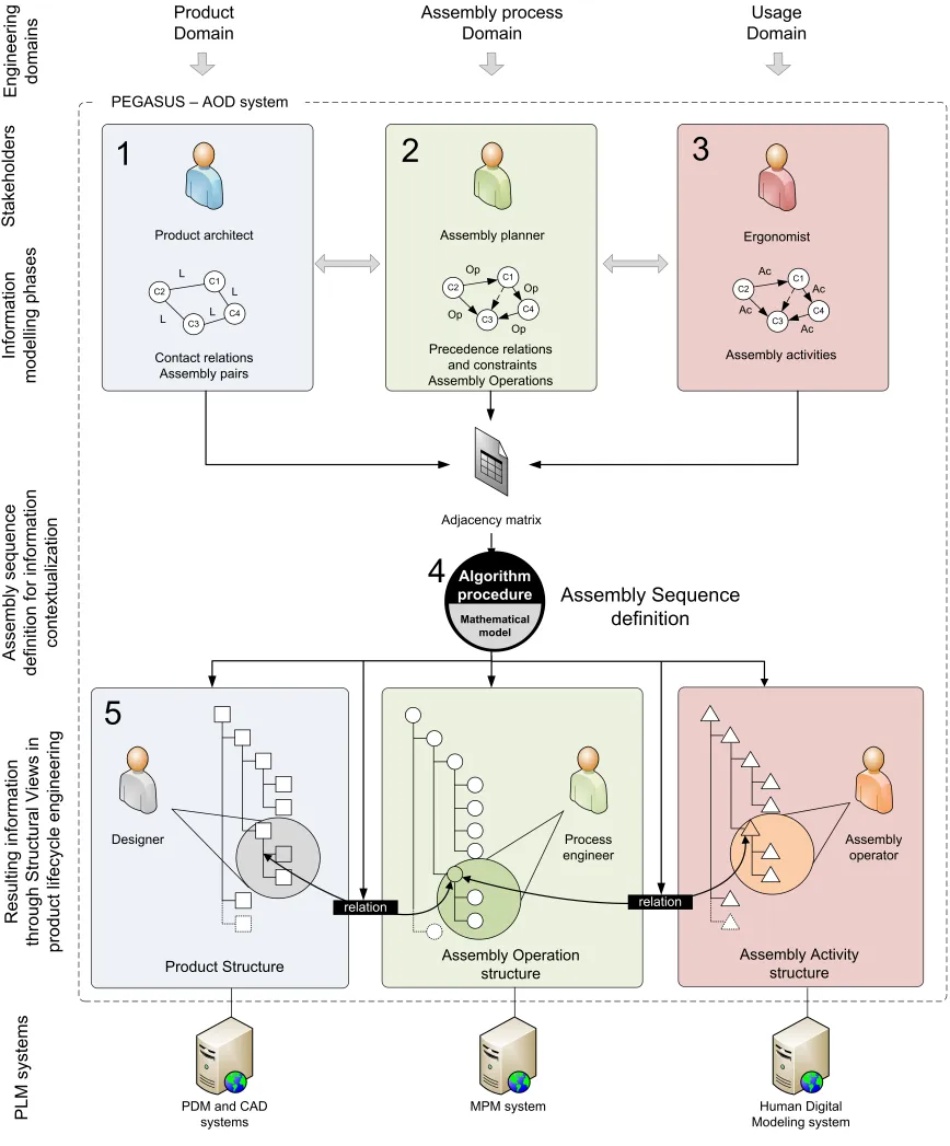
The proposed AOD methodology (Fig. 1) involves several product lifecycle stakeholders related to assembly considerations, which starts with a high level of abstraction into the preliminary design stage. The first step consists of setting up a multidisciplinary and multifunctional working team within a company integrating specific roles of the stakeholders, consisting of:
- the product architect who manages product structure and modeling context for designers in consistency with functional requirements,
- the designer who specifies and defines product geometric information according to product geometric requirements and lifecycle engineering constraints,
- the assembly planner who plans assembly sequences, assembly operations and allocates assembly resources,
- the process engineer who produces and brings out all relevant information for a specific/standard assembly process.
- the ergonomist who defines and analyses the assembly operator activity during the assembly of the product.
As a result, this integrated framework (Fig. 1) brings the following added value to the AOD approach:
1. Starting from a product structure and its associated breakdown fulfilling functions and previously defined requirements, the product architect defines a liaison graph by describing contact relations and assembly pairs between product components in which estimated mass are described.
2. Based on the liaison graph defined by the product architect, the assembly planner assigns assembly operation for each contact relation regarding assembly pairs. As a result, the planner defines a directed graph by introducing the precedence constraints.
3. Based on the directed graph defined by the product architect and the assembly planner, the ergonomist identifies and describes the identified assembly operations. Besides, he/she introduces component mass and time constraints and limitations as decision making criteria for selecting future sub-assemblies. 4. The directed graph is converted into an adjacency matrix as relevant input information for the
algorithm. The proposed framework is based on a mathematical model which will be described in
section 3.2. The algorithm integrates the definition of sub-matrix types related to sub-assembly types, and generates several sub-assembly alternatives with several dimensions. The assembly planner manages sub-assembly layers by taking into account criteria related to the ergonomics and assembly process engineering. Once the assembly sequence is defined, the ASDA algorithm creates XML files for each engineering domain, namely product structure, assembly operations structure, and assembly activities structure. This in turn enables information propagation to others PLM systems such as CAx, PDM, and MPM (Manufacturing Process Management) systems.
5. Starting from each generated structure, designers, process engineers and assembly operators can work concurrently on a local and single product perspective definition integrating contextualized information. For instance, designers could work on a skeleton geometry model which integrates geometric constraints related to DFA rules and assembly sequence.
It is necessary to highlight the novel aspect of the proposed framework. Whilst the traditional approaches tend to perform tasks 1, 2, and 3 in sequential fashion, the novel aspect of this work lies in that a concurrent execution of tasks 1, 2, and 3 is fully supported as indicated by bidirectional arrows among them. This is enabled because all these three tasks provide inputs to the critical adjacency matrix, from which anyone of the three stakeholders can access lifecycle related design information at any time. The following section will describe the underlying ASDA algorithm which enables the above capabilities.
Fig. 1. Assembly-Oriented Design framework as functional part of PLM strategy
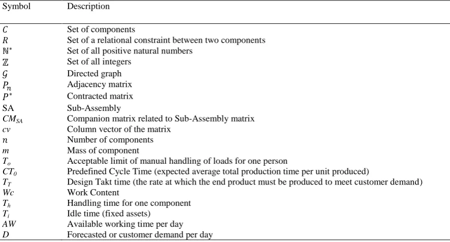
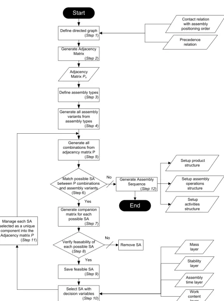
In the dynamic context of the suggested framework, the authors focus on the mathematical model describing the ASDA algorithm of generating assembly sequences for product structure engineering. This algorithm is considered as the body of the AOD framework by the definition of sub-assembly types, DFA heuristic rules in mathematical equations, and by the resulting domain-specific view generation based on the defined assembly sequence. A flowchart is introduced to represent the algorithm in which each step is described into the following sub-sections (Fig. 2). A summary of notations used in this model is given in Table 1.
Table 1
Notations used in the mathematical model
Symbol Description
Set of components
Set of a relational constraint between two components Set of all positive natural numbers
Set of all integers Directed graph Adjacency matrix Contracted matrix
SA Sub-Assembly
CMSA Companion matrix related to Sub-Assembly matrix
cv Column vector of the matrix Number of components
m Mass of component
To Acceptable limit of manual handling of loads for one person
CT0 Predefined Cycle Time (expected average total production time per unit produced)
TT Design Takt time (the rate at which the end product must be produced to meet customer demand)
Wc Work Content
Th Handling time for one component
Ti Idle time (fixed assets)
AW Available working time per day D Forecasted or customer demand per day
3.2.1 Definition of directed graph and adjacency matrix (steps 1 and 2 of Figure 2)
A directed graph model with directed edges is set up to represent the abstract information from each engineering domain which takes into account all the preliminary information, and is much useful for visual analysis. This model is converted into a matrix form called “adjacency matrix” which is used for computer processing in the proposed framework. The adjacency matrix of a directed graph is always anti-symmetric about the diagonal line running from the upper left entry to the lower right.
Let be the finite set of all product components with a cardinality of . Let be the finite set of all relational constraints between two components with a cardinality of . Suppose a directed graph where vertices or nodes represent components and ordered pairs of vertices called directed edges (or bonds) represent relational information. Among these relations, we define various abstraction levels of input information from each stakeholder‟s point of view, as described into the proposed framework. At first, this graph models include two types of information:
- contact relation as a physical relation between two components (in solid line),
- precedence relation defining an assembly logical order for two components in contact (solid arrow) and in non-contact (dot pattern arrow).
Let be the adjacency matrix defined from the directed graph as a fixed anti-symmetric n by n matrix
entries (Fig. 3).
Fig. 3. Directed graph and related adjacency matrix
Described in the directed graph , a comprehensive product lifecycle relationships can be defined into an adjacency matrix. These relations about the contact and precedence information are defined as follows:
;
;
In this framework, the adjacency matrix is decomposed into three layers with different information from a stakeholder‟s point of view. The first layer contains contact relation information, the second one defines precedence relations and assembly operation time related to assembly operations, and the third describes work content of activities. Assembly operation time and work content are associated to each from the first layer. The following sections detail the algorithm proposed and implemented in this research.
3.2.2 Sub-Assembly identification rules (steps 3 to 6 of Figure 2)
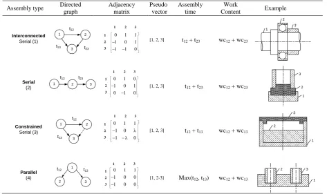
[image:9.595.62.536.450.731.2]Starting from the previous adjacency matrix, it is important to identify possible sub-assemblies with the definition of assembly types. As a result, four kinds of assemblies can be identified, and directed graph, matrix form, pseudo-vector, assembly time and work content are listed in Table 2. For each type, a pseudo-vector can be generated to represent the assembly sequence. The authors use a “,” between two components to describe a serial assembly operation and a “-“ for parallel assembly operation. Assembly time and work content are associated to each directed edges and therefore computed for each kind of assembly. For instance, a serial assembly will have one contact relation between two consecutive components only, whereas a parallel assembly will have all other components connected only to a base component.
Table 2
Assembly Types of three components and related relevant information for computer processing
Assembly type Directed graph Adjacency matrix Pseudo- vector Assembly time Work
Content Example
Constrained
Serial (3)
1 2
3
t12
t13
0 λ 1 λ 0 1 1 1 0
1 2 3
1
3
2 [1, 2, 3] t12 + t13 wc12 + wc13
1 2 3 Parallel (4) 2 3 1
t12 t13
0 0 1 0 0 1 1 1 0
1 2 3
1
3
2 [1, 2-3] Max(t12, t13) wc12 + wc13 1
2 3 Interconnected Serial (1) 1 2 3 t12 t23
t13
0 1 1 1 0 1 1 1 0
1 2 3
1
3
2 [1, 2, 3] t12 + t23 wc12 + wc23
3 2
1
Serial
(2)
1 2 3
t12 t23
0 1 0 1 0 1 0 1 0
1 2 3
1
3
2 [1, 2, 3] t12 + t23 wc12 + wc23
1 2 3
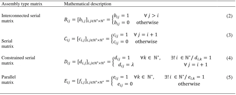
Table 3
Mathematical description of each kind of assembly matrix
Assembly type matrix Mathematical description
Interconnected serial matrix
(2)
Serial matrix
(3)
Constrained serial matrix
(4)
Parallel matrix
(5)
For each assembly, the ASDA algorithm generates all the permutations in order to facilitate sub-matrices recognition from the adjacency matrix . This approach avoids time-consuming process mainly by investigating subassemblies through simplified and smaller sub-matrices as shown in Table 2.
Let be the set of all combinations of each matrix related to assembly types:
(6)
Let be the set of all combinations of sub-assembly matrix variants:
(7)
Once the definition and generation of assembly variants are completed, the total number of valid matrix combinations to be tested is described below. here represents the set of all combinations of k elements taken from n elements of in order to represent combinations of k by k matrices into .
(8)
Let be the set of candidate sub-assemblies matrices of k dimension in :
(9)
As soon as the full match is found, each sub-matrix representing possible SA can be tested in order to check the engineering feasibility through interference with the remaining components.
3.2.3 Sub-Assembly validation rules (steps 7 to 9 of Figure 2)
For each identified SA from the generated adjacency matrix, a companion matrix CM is associated and extracted regarding the relations between SA components and the remaining components of the product in order to determine if the SA is feasible from an interference point of view (Fig. 4). As a result, a rule must be applied with the associated companion matrix (10). Let be the set of companion matrices related to candidate sub-assemblies of k dimension in . Let be the set of fixed anti-symmetric k by k matrix in
(10)
[image:11.595.209.495.607.715.2](a) Directed graph (b) Adjacency matrix
Fig. 4. Sub-assembly SA identification and related companion matrix CMSA
So if the signs of non-zero elements in kth column are neither all positive nor all negative, there are interferences between the sub-assembly matrix set and other remaining components. Therefore, this set cannot be considered as a feasible assembly from an engineering point of view. Once the engineering feasible sub-assemblies identified, further decision supports based on specific criteria such as stability, mass and so on, can be used to provide guidance to choose suitable sub-assemblies.
3.2.4 Decision support (step 10 of Figure 2)
In order to provide a decision support for the sub-assembly selection, an initial assembly context previously defined by the assembly planner will have to be taken into account. Starting from the forecast (or customer) demand per day and the available work time per day, the design Takt time is defined to indicate the assembly frequency of sold product and is calculated automatically.
(11)
Decision support variables and the procedure use information that have been modeled into the several graph layers, as described in the proposed AOD framework. Firstly, predetermined mass of product components and assembly time associated to assembly operation are used as decision making criteria. In addition, criterion related to assembly stability with kinematics pairs is explored. The processing rules to establish these engineering criteria are described below.
Let m be the predetermined mass associated to each product component. Let To be the acceptable limit of manual handling of loads for one person. For each engineering feasible sub-assembly, the mass (12) and the acceptable limit of manual handling of loads limitations (13) are calculated automatically and limited by predetermined constraints such as and defined in the system complying with NF X35-109 and NF EN 1005-5 ergonomics standards [45,46].
(12)
(13)
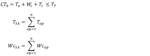
Concerning assembly operation, the authors have defined for each assembly type a calculated and predetermined cycle time using standard assembly operation time , idle time and work content .
(14)
(15)
(16)
For the stability criteria, the main rule defines a SA stable if no mobility exists between its own components, in other words, if all its components are held in position.
Once the assembly planner has chosen engineering feasible sub-assemblies in the first procedure cycle, the ASDA algorithm processes each selected SA as a single component to be reintroduced in the adjacency matrix . Based on , a new smaller adjacency matrix called contracted matrix is generated (Fig. 5). Thus, others sub-assemblies can also be detected and selected in another assembly layer. This matrix depends on the k by k
selected SA matrices, and the size of is: n – k + 1. To build , several rules regarding SA matrix and related companion matrix must be followed in order to assign entries. These rules describe how SA inherits the relational information of its internal components with the remaining components.
If (all elements in the jth columns of companion matrix = 0) ThenpSA,j= 0
If (all non zero elements in the jth columns of companion matrix > 0 and = ) ThenpSA,j =
OtherwisepSA,j = 1
If (all non zero elements in the jth columns of companion matrix < 0 and = - ) ThenpSA,j= -
OtherwisepSA,j = -1
(17)
(a) Contracted graph (b) Contracted matrix
Fig. 5. Contracted graph and related contracted matrix
3.2.6 Assembly sequence and resulting information (step 12 of Figure 2)
At the end of the procedure, an assembly sequence is computed as a master result for specific product structure for each engineering domain. Consequently, the setup product structure (Fig. 6) based on the assembly sequence will be considered as a core contextual support for AOD in which several elements are highlighted including:
- Sub-Assembly: this is the sub-assembly selected by the assembly planner regarding assembly type, assembly time, work content, mass and stability,
- Skeleton: describing, for each assembly level, the context in which parts are assembled, - Part: elementary component composing the sub-assembly, e.g. base part, fastener, etc., - Assembly parameters: managing assembly data in the local view.
Fig. 6. Setup product structure defined by the assembly sequence
At each SA level in the product structure, a base part will be identified according to the SA pseudo-vector previously defined. The base part is considered as the reference component for the SA, that is to say the component on which the other components will be assembled.
4. Case study in an industrial application
The above concurrent approach has real industrial relevance, as manufacturing companies have a real need in integrated methods for product design and assembly process engineering, especially at their interfaces. This approach has been applied to a company as a case study. The chosen part is a Catalytic-Converter and Diesel Particulate Filter sub-system (Cat-Converters & DPF) belonging to an exhaust system from an industrial automotive supplier and this case study is designed to illustrate the efficiency of the proposed AOD methodology.
4.1 Case study: Catalytic Converters and Diesel Particulate Filter and their design problem definition
The company is an automotive supplier working on exhaust system development for car manufacturers. Engineering departments are facing information exchange issues, mainly between engineering design and assembly process engineering departments, because of the numerous information systems implemented in the company and the lack of information integration at the various design stages. Assembly issues are often identified in the prototype phases in which the detailed design is finalised and to be validated. As a result of such a design approach, several problems have been highlighted:
- ASP phase is performed in a sequential way and therefore introducing rework in the product development, - Numerous BOM (Bill of Materials): E-BOM (Engineering), CAD-BOM (CAD), M-BOM (Manufacturing) defined in a sequential and independent way into various systems (CAD, PDM, MPM, ERP, etc.),
[image:13.595.61.531.253.329.2]- Assembly issues are often neglected during the design process, especially at the preliminary design stage.
Table 4
Parts list for the case study
No. Name Type No. Name Type
1 DPF Sub-Assembly 7 Bracket right Sub-Assembly
2 Cat-Converter Sub-Assembly 8 Bracket left Sub-Assembly
3 Insulating right Sub-Assembly 9 Pressure bracket Part
4 Insulating left Sub-Assembly 10 Left Half-shell link Part
5 Inlet Sub-Assembly 11 Right half-shell link Part
6 Outlet Sub-Assembly
(a) ISO view (b) Exploded view
Fig. 7. Catalytic-Converters and Diesel Particulate Filter
4.2 The approach based on the framework
The authors focus on three roles: the product architect, the assembly planner and the ergonomist working into different departments of the company. Various initial conditions must be introduced in order to launch the ASDA algorithm. First of all, the company applies a “one piece flow” strategy to achieve just-in time manufacturing. As a result, the design Takt time was calculated with a forecast demand of 500 units per day and 450 min of available working time in order to limit each predetermined cycle time as follows:
D = 500 units,
AW = 1 shift/day = 8.5 hrs – 0.5 hr (lunch) – 0.5hr (breaks) = 450 mins.
Next, the ergonomist also introduces mass and the acceptable limit of loads for manual handling for one person in the reference condition for manual assembly according to [45]:
All these initial conditions are considered as decision making support constraints for sub-assemblies selection. A directed graph and the corresponding adjacency matrix including three layers have been generated into PEGASUS (Fig. 8). These ones integrate all relevant input information from all stakeholders involved for assembly sequence and product structure definition.
(a) Directed graph (b) Adjacency matrix
4.3 System execution
With relevant information as inputs for the algorithm of assembly sequences definition, the assembly planner introduces assembly time regarding assembly operation for each contact relation in a second layer. The third layer integrates work content related to assembly time. Indeed, work content is defined by the ergonomist to bring required time to perform other related operations such as handling, insertion and inspecting operations. For the proposed experimentation, the authors focus on sub-assembly identification with in order to have a fine granularity level for the assembly sequence definition. Once all these initial conditions and relevant information identified, the assembly sequence of the product will be defined. The ASDA algorithm computed 3 cycles, therefore representing 3 assembly layers in order to assemble all the product components shown in PEGASUS (Fig. 9). The result for the case study is presented below (Fig. 10):
Assembly sequence = {(((2,5,10),11,3),((4,1,6),7,8),9)} with 5 serial sub-assemblies: SA1 = (2,5,10),
SA2 = (4,1,6),
SA3 = (SA2,7,8) = ((4,1,6),7,8),
SA4 = (SA1,11,3) = ((2,5,10),11,3),
SA5 = (SA4,SA3,9) = (((2,5,10),11,3),((4,1,6),7,8),9).
The component 2, 4, SA2, SA1, and SA4 are considered as base part in each generated SA.
Fig. 9. Assembly planner view integrating directed graph and choice of feasible sub-assemblies
Fig. 10. Representation of the resulting assembly sequence
Using the PEGASUS system, the product and the assembly operation structures are automatically generated. The resulting information of the product structure and assembly structure could also be used by other related systems such as PDM, MPM, and CAD system through XML files. Fig. 11 shows a setup product structure defined in CATIA v5 through an import of CATscript file automatically generated from PEGASUS.
Fig. 11. Assembly-oriented product structure based on the previous assembly sequence and defined by a CATscript file into CATIA v5
Fig. 12. Functional skeleton model of the Catalytic-Converters and Diesel Particulate Filter considered for the experimentation
4.3 Discussions
ASP is a crucial step to enable feasible engineering product solutions. The authors have focused on extracting and applying assembly sequence definition at the preliminary design stage to generate an assembly-oriented product structure solution by constraining the product design with assembly process information. This approach differs significantly from the traditional engineering design approaches that define assembly sequence after the detailed design stage. In addition, the proposed approach offers a gain in productivity and efficiency by avoiding rework caused by a lack of consideration of assembly, as the preliminary design decisions are made based on assembly considerations and requirements. The AOD framework takes into account the management of information status, relationships and changes in order to keep traceability and consistency of decision making to meet the overall PLM requirements and challenges [47].
Traditional design process doesn‟t support the designer to have access to information of the assembly process. For life-cycle oriented design, this is critical to help designer‟s decision making. Such unavailability of assembly information can be avoided by creating a link between the product development process and the ASP phase and this case study demonstrated such a feasible and effective approach.
5. Conclusion and future work
Current status and challenges in DFA and ASP approaches have been highlighted in this paper. Build on these, an Assembly-Oriented Design framework based on a rigorous and novel mathematical model capturing DFA rules and engineering decision making process is proposed and implemented in a Web-based PEGASUS system. The framework approach enables the concurrent generation of preliminary design solution information and the assembly sequence information. Such an approach hence follows a designer to access to this critical assembly information ever at the preliminary design stage and consequently enable the designer to make assembly oriented and informed decisions. Design decisions made in such a manner allow the designer to foresee any potential assembly difficulties and issues at much early stage, hence avoiding any rework. This is the fundamental difference of the proposed work to other design for assembly work and this is also where the authors argue the key contribution this work made to the field. The above idea has been proved and demonstrated through an industrial automotive supplier case study which has been implemented to evaluate the proposed approach and address advantages and drawbacks of the AOD framework.
Considering product design and assembly sequence planning in a concurrent way is a huge challenge as there are challenges to be addressed in providing right information of different life-cycle phase at right time from different stakeholders. It is important to focus on several strategic and tactical aspects of the product that the issue can be used as a natural launch pad for integrated product-process design in PLM context. This work paved the way for future research and development in this field by providing a framework and associated Web-based tool, however the authors will need to address further research issues. One area of future research is to enable proactive support feature of the framework further by providing timely assembly relevant guidelines and heuristics knowledge into the preliminary design process at the right time [48]. Another aspect is to improve the robustness of assembly sequence generated concurrently during the early design as there is certain information missing and this may be addressed by deploying full product functional definition and introducing assembly functional axis. The future work will also support the product modeling phase by introducing the definition of geometric skeletons related to the assembly sequence. A multiple-view model will also be implemented into PEGASUS in order to manage information and knowledge throughout the product lifecycle and from various identified views according to stakeholders‟ concerns.
6. Acknowledgements
The research activity is a part of the CoDeKF Research Project (Collaborative Design and Knowledge Factory) which has been funded by the French Automotive Cluster „Pôle de Compétitivité Véhicule du Futur‟. The authors would like to thank Bernard Mignot for Algorithm Development, Faurecia Emissions Control Technology for this collaboration, and all the financial contributors of this research and technology program: DRIRE de Franche-Comté, Communauté d‟Agglomération du Pays de Montbéliard, Conseil Général du Doubs, and Conseil Régional de Franche-Comté.
7. References
[1] L. Wang, S. Keshavarzmanesh, H.-Y. Feng, R.O. Buchal, Assembly process planning and its future in collaborative manufacturing: a review, Int. J. Adv. Manuf. Tech., 41 (2009) 132-144.
[2] L. Yu-liang, Z.O Wei, Development of an integrated-collaborative decision making framework for product top-down design process, Robot. Comput.-Integr. Manuf., 25 (2009) 497-512.
[4] F. Demoly, S. Gomes, B. Eynard, L. Rivest, PLM based approach for Assembly Process Engineering, Int. J. Manuf. Res., 2010, in Press.
[5] A. Bourjault, Contribution à une approche méthodologique de l‟assemblage automatisée: Elaboration automatique des séquences opératoires, Thèse d‟Etat, Université de Franche-Comté, Besançon, France, November, 1984.
[6] T. De Fazio, D. Whitney, Simplified Generation of all mechanical assembly sequences, IEEE J. Robot. Autom., 3(6) (1987) 640-658.
[7] L.S. Homem de Mello, A.C. Sanderson, Representations of Mechanical assembly sequences, IEEE Trans. Robot. Auto., 7(2) (1991) 211-227.
[8] M. Santochi, G. Dini, Computer Aided Planning of Assembly Operations: The selection of assembly sequences, Robot. Compu.- Integr. Manuf., 9(6) (1992) 439-446.
[9] C. Mascle, Approche méthodologique de détermination de gammes par désassemblage, Thèse de l‟Ecole Polytechnique de Lausanne, 1990.
[10]T. Gu, Z. Xu, Z. Yang, Symbolic OBDD representations for mechanical assembly sequences, Comput-aided Des., 40 (2008) 411-421.
[11]L. Laperrière, H.A. ElMaraghy, GAPP: A Generative Assembly Process Planner, J. Manuf. Systems, 15(4) (1996) 282-293.
[12]R.B. Gottipolu, K. Ghosh, Representation and selection of assembly sequences in computer-aided assembly process planning, Int. J. Prod. Res., 35(12) (1997).
[13]R.B. Gottipolu, K. Ghosh, A simplified and efficient representation for evaluation and selection of assembly sequences, Comput. in Ind., 50 (2003) 251-264.
[14]Y.Z. Zhang, J. Ni, Z.Q. Lin, X.M. Lai, Automated sequencing and sub-assembly detection in automobile body assembly planning, J. Mat. Process. Tech., 129 (2002) 490-494.
[15]M-C. Lin, Y-Y. Tai, M-S. Chen, C.A. Chang, A Rule Based Assembly Sequence Generation Method for Product Design, Conc. Eng., 15 (2008) 291-308.
[16]F. Bonneville, C. Perrard, J-M. Henrioud, A genetic algorithm to generate and evaluate assembly plans, IEEE Symp. Emer. Tech. Fact. Autom., 2 (1996) 231-239.
[17]P. De Lit, P. Latinne, B. Rekiek, A. Delchambre, Assembly planning with an ordering genetic algorithm, Int. J. Prod. Res., 39(16) (2001) 3623-3640.
[18]G.C. Smith, SS-F. Smith, An enhanced genetic algorithm for automated assembly planning, Robot. Comput.-Integr. Manuf., 18(5-6) (2002) 355-364.
[19]H-E. Tseng, W-P. Wang, H-Y. Shih, Using memetic algorithms with guided local search to solve assembly sequence planning, Exp. Sys. Appli., 33 (2007) 451-467.
[20]Q. Su, A hierarchical approach on assembly sequence planning and optimal sequences analyzing, Robot. Comput.-Integr. Manuf., 25(1) (2009) 224-234.
[21]XF. Zha, H. Du, A PDES/STEP-based model and system for concurrent integrated design and assembly planning, Comput-aided Des., 34(14) (2002) 1087-1110.
[22]T. Dong, R. Tong, L. Zhang, J. Dong, A knowledge-based approach to assembly sequence planning, Int. J. Adv. Manuf. Tech., 32(11-12) (2007) 1232-1244.
[23]N.W. Bowland, J.X. Gao, R. Sharma, A PDM- and CAD-integrated assembly modelling environment for manufacturing planning, J. Mat. Process. Tech., 138 (2003) 82-88.
[24]X.G. Ming, J.Q. Yan, X.H. Wang, S.N. Li, W.F. Lu, Q.J. Peng, Y.S. Ma, Collaborative process planning and manufacturing in product lifecycle management, Comput. in Ind., 59(2-3) (2008) 154-166.
[25]M.M. Andreasen, S. Kahler, T. Lund, Design for Assembly. IFS Publications Ltd, Springer, Verlag, UK, 1983. [26]A. Redford, J. Chal, Design for Assembly - Principes and Practice, McGraw- Hill Inc, England, 1994.
[27]S. Miyakawa,T. Shigemura, The Hitachi assemblability evaluation method (AREM), Proceedings Jpn. Soc. Mech. Eng., Conf. Mfg. Syst. Environ.-looking Toward 21st Century, (1990) 277-282.
[28]Y. Yamagiwa, An Assembly Ease Evaluation Method For Product Engineers: DAC, Techno Japan, 21(12) (1988). [29]R. Stone, D. McAdams, V.J. Kayyalethekkel, A product architecture-based conceptual DFA technique, Des. Stu., 25(3)
(2004) 301-325.
[30]G. Boothroyd, P. Dewhurst, Product Design for Assembly, Boothroyd Dewhurst, Inc., Wakefield, RI, USA, 1990. [31]G. Boothroyd, Product design for manufacture and assembly, Comput-aided Des., 26(7) (1994) 505-520. [32]K.G. Swift, Design for assembly Handbook, Salford University Industrial Centre Ltd., UK, 1981.
[33]D.E. Whitney, J.L. Nevins, T.L. De Fazio, The strategic approach to product design, Design and Analysis of Integrated Manufacturing Systems, (1988) 200-223.
[34]D.E. Whitney et al. Designing Assemblies, Res. in Eng. Des., (11) (1999) 229-253.
[35]S. Lee, Y.G. Shin, Assembly Co-planner: Cooperative Assembly Planner Based on Subassembly Extraction, J. Int. Manuf., 4(3) (1993) 183-198.
[36]P. Pu, An Assembly Sequence Generation Algorithm Using Case-based Search Techniques, IEEE Int. Conf. Robot. Autom., Nice, France, (1992) 2425-2429.
[37]Q. Su, Applying case based reasoning in assembly sequence planning, Int. J. Prod. Res., 45(1) (2007) 29-47.
[38]T.L. De Fazio, S.J. Rhee, D.E. Whitney, Design-Specific Approach to Design for Assembly for Complex Mechanical Assemblies, IEEE Trans. Robot. Autom., 15(5) (1999) 869-881.
[39]C. Mascle, Feature-based assembly model for integration in computer-aided assembly, Robot. Comput.-Integr. Manuf., 18 (2002) 373-378.
[41]O. Coma, C. Mascle, M. Balazinski, Application of a fuzzy decision support system in a design for assembly methodology, Int. J. Comput. Intell. Mfg, 17(1) (2004) 83-94.
[42]F. Demoly, S. Gomes, B. Eynard, J-C. Sagot, Towards a Design For Assembly Approach based on SysML Paradigm and PLM systems, 2nd CIRP Int. Conf. on Assembly Technologies and Systems (CATS), 21-23 September 2008, Toronto, Canada, ISBN: 978-0-9783187-1-0, pp. 100-113.
[43]F. Demoly, S. Gomes, B. Eynard, L. Rivest, J-C. Sagot, Assembly-oriented product structure based on preliminary assembly process engineering, International Conference on Engineering Design, ICED‟09, 24-27 august 2009, Stanford, CA, USA.
[44]H.P. Wiendahl, H.A. ElMaraghy, P. Nyhuis, M.F. Zäh, H.H. Wiendahl, N. Duffie, M. Brieke, Changeable Manufacturing – Classification, Design and Operation, CIRP Annals, 56(2) (2007) 783-809.
[45]X35-109, Acceptable limits of manual load carrying for one person, French Norm, 1989, ISSN 0330-3931.
[46]Norme européenne NF EN 1005-5, Sécurité des machines, Performances physique humaine. Partie 5 : Appréciation du risque relatif à la manipulation répétitive à fréquence élevée, Mai, 2007.
[47]V. Srinivasan, An integration framework for product lifecycle management, Comput-aided Des., (2010) in Press. [48]X. T. Yan, J Borg, N P Juster, Concurrent modelling of components and realization systems to support proactive design