Article
A Suitable Constitutive Model for Solid Tire Analysis
under Quasi-Static Loads using Finite Element
Method
Juthanee Phromjan and Chakrit Suvanjumrat
*Laboratory of Computer Mechanics for Design (LCMD), Department of Mechanical Engineering, Faculty of Engineering, Mahidol University, Nakhon Pathom 73170, Thailand
*E-mail: [email protected] (Corresponding author)
Abstract. The rubber solid tire was built using three different compound layers. In order
to develop solid tire, the finite element method (FEM) was employed to model and analyze its performance. The constitutive model was important to describe the simulated results of FEM; therefore, the hyperelastic material models were implemented for each compound of solid tire layers. The second order Ogden model was the most agreement with the compression test of the rubber compound specimens. The R2 of internal, middle
and tread compound layer was 0.990, 0.988 and 0.989, respectively. The solid tire model was developed and tested with the compressive loads. Particularly, the compressive loads on the solid tire were performed with the experiment regarding to the simulation. The solid tire model which was complied with the Ogden model had good agreements with the experimental results. It had an average error less than 8.49%. The Ogden model which was implemented with the mechanical property of rubber compound of solid tire was found that it would be advantageous to design and develop the novel solid tire in the future work.
Keywords: Constitutive model, solid tire, analysis, quasi-static load, finite element method.
ENGINEERING JOURNAL Volume 22 Issue 2
1.
Introduction
The tire testing had employed the finite element method (FEM) to simulate the test in place of the physical experiment [1-3]. The FEM could be used well to develop and design the tires which it was caused the decrease of cost and time consuming by using the trial and error method. In order to receive the accurate results, the constitutive models were important to develop for description of the deformable behavior of rubber material of the tires. The constitutive model was satisfied for the rubber tire analysis, such as the Mooney-Rivlin, Arruda-Boyce, Yeoh and Ogden. Mohsenimanesh et al. [4] used Mooney-Rivlin model to describe the deformable behavior of rubber material which was the tread of tractor tire for analyzing the contact pressure distribution. Alkan et al. [5] created the pneumatic tire model using the Mooney-Rivlin material model for analyzing the vertical stiffness of tire. Yang and Olatunbosun [6] had analyzed the racing tire using FEM. The Yeoh model was good to describe the stress-strain characteristic of the racing tire material. The vertical stiffness of racing tire was optimized for the tire improvement. Behroozi et al. [7] created the aircraft tire model for the tire burst and inflation analysis using FEM with the Yeoh material model. Baranowski et al. [8] had implemented Ogden formulation with the rubber material of the trucks supporting military operations tire. Baranowski et al. [9] also had applied Ogden formulation for the rubber material of pneumatic tire model under the dynamic analysis comprising of the radial reflection test, bounce test, and blast loading test. Wei and Olatunbosun [10, 11] selected Yeoh model for the pneumatic tire to analyze the ride comfort assessment, cornering performance, and relaxation length for a constant slip angle of the rolling tire model. These constitutive models which were carried out to use with the FEM were obtained by implementation in the stress-strain characteristic of tire material. The tensile test specimen was referred to the thin rubber material which was the components of the pneumatic tires.
The solid tire was produced deliberately to support the heavy load; therefore, it was concerned with the compressive load unavoidably. In order to obtain the stress-strain characteristic of the solid tire material, the compression test should be used to test material properties of the solid tires. The compressive specimens had a cylindrical shape which was referred to the ASTM D575-91 [12]. They were difficult to cut directly from the solid tires; therefore, they were prepared from the rubber compounds which were used to produce the solid tires. The curing time for solid tires was more than the specimen; therefore, the moving die rheometer (MDR) was used according to the ASTM D5289 [13] to characterize the rubber compound curing. Hu et al. [14] had been designed the compression packer which was recommended to use the rubber material B75. They had determined that the optimized constitutive model for this material and the Ogden and Arruda-Boyce were adopted for the constitutive model. The Ogden model was suitable for a large strain that happening on the B75 material. Sesso et al. [15] characterized a rubber membrane which was used as the air-oil separator in vibration dampers of helicopter blades. The Ogden model was a material model for describing the mechanical behavior of membrane under oil pressure conditions by the FEM for evaluation its lifetime. Wu et al. [16] had used the explicit finite element method to analyze a sliding lead rubber bearing (SLRB). The Mooney-Rivlin model was implemented for the rubber component of SLRB and could reproduce the vertical stiffness and hysteresis behavior of the SLRB. Zhou et al. [17] created the O-ring model for analyzing the seal capacity using FEM. The Mooney Rivlin model was used to explain the deformable behavior of nitrile-butadiene rubber which was used for the material of O-ring. Some constitutive models were developed to characterize the stress-strain behavior of rubberlike material under the compression test. The response in compression test which was the deformation of the slightly compressible rubbers was proposed [18]. Although the constitutive models were applied and developed for the compression test result of rubber material, they were lack of the constitutive model of the rubber solid tires. Therefore, the simulation of solid tire was not widely used in the solid tire industry to develop their current products. This research had developed the approach to determine the constitutive model of the solid tires for the compression test by FEM. The solid tire model which had the suitable material property also was developed for simulation of the compression test. The finite element model of solid tire will be advantageous to develop the good quality of solid tire for manufacturing in the future.
2.
Constitutive Models
rubber material properties comprising of thepolynomial, Mooney-Rivlin, Yeoh, Arruda-Boyce, and Ogden model.
2.1. Polynomial Model
The polynomial model is formulated in terms of the two strain invariants of the left Cauchy-Green deformation tensor which is written by the following equation.
𝑈 = ∑𝑛𝑖=1𝐶𝑖𝑗(𝐼̅1− 3)𝑖(𝐼̅2− 3)𝑗+ ∑𝑖=1𝑛 𝐷1𝑖(𝐽𝑒𝑙− 1)2𝑖 (1)
where , 𝐶𝑖𝑗 is the material constant, 𝐼̅1 is the first invariant of the deviatoric strain, 𝐼̅2 is the second invariant
of the deviatoric strain, 𝐷𝑖 is the compressibility, and 𝐽𝑒𝑙 is the elastic volume ratio.
2.2. Mooney-Rivlin Model
The simplest polynomial model is Mooney-Rivlin model which is written the strain energy function as follows:
𝑈 = ∑𝑛𝑖=1𝐶𝑖0(𝐼̅𝑖− 3)𝑖+ ∑𝑛𝑖=1𝐷1𝑖(𝐽𝑒𝑙− 3)2𝑖 (2)
where , 𝐶𝑖0 is the material constant which described the shear behavior of material, 𝐼̅𝑖 is the invariant of the deviatoric strain,𝐷𝑖 is the constant of material compressibility, and 𝐽𝑒𝑙 is the elastic volume ratio.
2.3. Yeoh Model
The Yeoh model [19] is expressed the strain energy function as follows:
𝑈 = ∑3 𝐶𝑖0(𝐼̅𝑖− 3)𝑖
𝑖=1 + ∑𝑛𝑖=1𝐷1𝑖(𝐽𝑒𝑙− 3)2𝑖 (3)
where , 𝐶𝑖0 is the material constant which described the shear behavior of material, 𝐼̅𝑖 is the invariant of the
deviatoric strain, 𝐽𝑒𝑙 is the elastic volume ratio.
2.4. Arruda-Boyce Model
The Arruda-Boyce model is based on an explanation of a molecular chain network. The strain energy is equal to the summation of strain energy of the individual chain orientation randomly in space [20]. It is written by the following equation.
𝑈 = 𝜇 ∑ 𝐶𝑖
𝜆2𝑖−2(𝐼̅1𝑖 − 3𝑖)
5
𝑖=1 +𝐷1(𝐽𝑒𝑙
2−1
2 − 𝑙𝑛(𝐽𝑒𝑙)) (4)
where 𝜇 is the initial shear modulus, 𝐶1 is 0.5, 𝐶2 is 0.05, 𝐶3 is 0.0105, 𝐶4 is 0.0027, 𝐶5 is 0.0077, 𝜆 is the
locking stretch, 𝐼̅𝑖 is the invariant of the deviatoric strain, 𝐷 is the double inverse bulk modulus at small strain, and 𝐽𝑒𝑙 is the elastic volume ratio.
2.5. Ogden Model
The Ogden model proposes the strain energy function based on principle stretches for incompressible material [21, 22]. The strain energy potential of Ogden has been written the important relation as follows:
𝑈 = ∑ 𝜇𝑖
𝛼𝑖(𝜆̅1
𝛼𝑖+ 𝜆̅
2 𝛼𝑖+ 𝜆̅
3 𝛼𝑖− 3)
𝑛
𝑖=1 + 4.5𝐾(𝐽1/3− 1)
2
where 𝜆̅𝑖= 𝐽−1/3𝜆
𝑖, 𝐽 = 𝜆1𝜆2𝜆3, 𝜆𝑖 is the deviatoric principle stretches, 𝐽 is the Jacobean determinant, 𝐾 is
the initial bulk modulus, and 𝜇𝑖, 𝛼𝑖 is constant.
3.
Experiments
This research was set up the compression tests for rubber specimens and solid tires. The compression test of specimens was performed in order to achieve the stress-strain characteristic of rubber compounds of the solid tire layers while the compression test of solid tire was performed to investigate the vertical deformation of solid tires.
3.1. Rubber Compounds
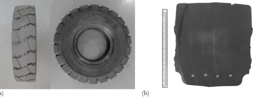
The solid tires were produced by V.S. Industry Tyres Co., Ltd. It was assembled by three natural rubber layers and steel wires (Fig. 1). Each rubber layer of solid tire was the different compounds. The industrial code of compound was M058, M047 and M067 for the internal, middle and tread layer of solid tires, respectively. The layers of solid tire were hard and difficult to cut for the preparation of specimen; therefore, the rubber compounds which were regarded to build the tire layers were prepared specimens for the standard test methods in compression. The specimen preparation was accorded to ASTM D575-91 which had the diameter and thickness of 28.6 and 12.5 mm, respectively. Figure 2a shows the rubber specimen which is produced from the rubber compounds. This specimen was much smaller than the solid tires; therefore, the curing time was also much less than the solid tires. In order to characterize the rubber compound curing, the MDR was performed according to the ASTM D5289. The compression test had been performed by the tensile and compression tester (INSTRON, Model: 5969) according to ASTM D575-91 on five pieces of specimen for each rubber compound. Each compression test was performed repeatedly three times to reduce the Mullins effect. Figure 2b shows the compression test of the rubber specimen by the tester. The vertical deflection of specimens was specified at -50% of their thickness for each compression test. The final test results would be collected to investigate the stress-strain characteristic of rubber compounds. The true stress vs. strain graph of each rubber compound was plotted for the curve fitting with the constitutive models.
3.2. Solid Tire
(a) (b)
Fig. 1. The testing solid tire in: (a) overview and (b) its section view to show its components.
(a) (b)
Fig. 2. (a) The rubber compound specimen and (b) the compression test of the rubber specimen.
Table 1. The characteristics of a KOMACHI solid tire.
Size
(inch) Rim Size (inch)
Tire Dimension (mm)
Weight (kg) Section
Width Outside Diameter
6.00-9 4.00E-09 145 523 27
(a) (b)
Fig. 3. The compression test of solid tire using (a) the tire stiffness tester (EKTRON TEK, Model: PL-2003) with (b) the position transducer and load cell installing under the measurement table.
Load cell
[image:5.595.73.489.80.243.2] [image:5.595.72.522.453.694.2]4.
Finite Element Method
The specimen was modeled using FEM and defined each material model which was comprised of the 2nd
order invariant, 3rd order deformation, Mooney-Rivlin, Yeoh, Arruda-Boyce, and Ogden model. The 3D
specimen model was divided by hexagonal elements which were used by the total number of 48,000 elements to create the finite element model. The vertical displacement was specified to compress on the top surface of the specimen model according to the physical experiment.
The KOMACHI solid tire is modeled in three dimensions using data from the 3D scanner (Artec 3D, Eva) and SolidWorks software (Fig. 4). The internal layer, middle layer and steel wire of solid tire model were meshed using hexagonal elements while the tread layer was meshed only using tetrahedral elements. Consequently, the internal, middle, tread layer and steel wires were built using 28,080, 22,320, 80,871, and 5,760 elements, respectively. The tread layer was set the element size finer than the internal and middle layer of solid tire model. Figure 5 shows the finite element model of the KOMACHI solid tire. The specimen and solid tire deformation cause of the compressive load are governed by the following equations.
𝜕𝜎𝑖𝑗
𝜕𝑥𝑗 + 𝛾𝑖 = 0 (6)
and
Fig. 4. The CAD model of KOMACHI solid tire. Fig. 5. The finite element model of KOMACHI solid tire.
𝜏𝑖 = 𝜎𝑖𝑗𝑛𝑗 (7)
where 𝜎𝑖𝑗 is Cauchy stress tensor, 𝑥𝑗 is the Cartesian coordinate, 𝛾𝑖 is the body force, and 𝜏𝑖 is the boundary traction components.
Equation 6 can be transformed using FEM [23] and written as follows:
(𝑲𝑬+ 𝑲𝑮) ∙ ∆𝒗 = 𝒇𝒍𝒐𝒂𝒅+ 𝒇𝒊𝒏𝒕𝒆𝒓𝒏𝒂𝒍 (8)
𝑲𝑬= ∫ 𝑩𝑻𝑫𝑩𝑑𝑉
0 (9)
𝑲𝑮= ∫(𝐿𝑗𝑝𝑘∙ 𝜎𝑘𝑖0 ∙ 𝐿𝑗𝑞𝑖− 2𝐵𝑗𝑝𝑘∙ 𝜎𝑘𝑖0 ∙ 𝐵𝑖𝑞𝑗)𝑑𝑉0 (10)
𝒇𝒍𝒐𝒂𝒅= 𝒇𝒃𝒐𝒅𝒚+ 𝒇𝒕𝒓𝒂𝒄𝒕𝒊𝒐𝒏= ∫ 𝑵𝑻∙ 𝜸𝑑𝑉0+ ∫ 𝑵𝑻∙ 𝝉𝑑𝑆0 (11)
𝒇𝒊𝒏𝒕𝒆𝒓𝒏𝒂𝒍= ∫ 𝑩𝑻∙ 𝝈𝑑𝑉0 (12)
[image:6.595.166.522.596.727.2]the element, 𝑩 is the strain interpolation matrix, 𝑉0 is the element volume, 𝑆0 is the element surface,𝐿𝑗𝑝𝑘 is the Cartesian different operator, and 𝑵 is the shape function matrix.
Each finite element model of solid tire layers was defined material model which had the good correlation with the stress-strain characteristic of the rubber compounds. The compressive loads were specified on the solid tire model according to the physical experiment. The RBE2 elements were defined to link the axis of solid tire model with its rim as the steel wheel fitting. The fixed boundary condition was assigned on the solid tire axis as same as the solid tire mounting on the axis of the stiffness tester. The vertical force was specified upward onto a rigid plate to lift and press the solid tire model. The contact boundary was specified between the solid tire model and rigid plate model to mimic the compression test of solid tire by the measurement table of tire stiffness tester. The finite element analysis (FEA) of the compression test on the specimen and solid tire was performed using MSC Marc software which was installed in a personal computer with a Core-i7 CPU and RAM memory of 8 GB.
5.
Results and Discussions
The results were explained step by step which was started on the implementation of rubber compound material to the final step as the finite element model of solid tire.
5.1. Curve Fitting Method
The constitutive models of three rubber compounds were determined using the curve fitting method. The six constitutive models which were comprised of the 2nd order invariant, 3rd order deformation,
Arruda-Boyce, Mooney-Rivlin, Yeoh, and Ogden were fitted with the stress-strain curve of rubber compounds by a curve fitting tool of MSC Marc software. Figure 6 shows the curve fitting results of six constitutive models for the rubber material code M058, M047 and M067. The Ogden model had a good agreement with the stress-strain curve of each rubber compound more than the other constitutive models. It could be a good description of the large strain behavior for the rubber compounds. Table 2 shows R2 results of six
constitutive models. The R2 of Ogden model which was more accurate than other constitutive models was
0.990, 0.988 and 0.989 for the stress-strain curve of the rubber material code M058, M047 and M067, respectively. The Ogden model which is correlated well with the stress-strain characteristics has the constant value for each rubber compound of the solid tire as shown in Table 3.
5.2. Compression Test
5.2.1. Specimen
5.2.2. Solid Tire
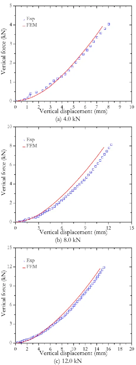
The Ogden model of each rubber compound was defined to be the material property of solid tire layers. The compression test on solid tire was simulated regarding to the physical experiment. The simulation results are shown in Fig. 9. The Von Mises stress and vertical displacement of solid tire were showed by the color contour. The maximum and the minimum value were yellow and blue, respectively. The large deformation of solid tire occurred at the tire tread which contacted to the rigid floor. The maximum Von Mises stress also occurred in the solid tire model when the tire tread contacted to the rigid floor (yellow color). The solid tire model and experimental tire were compared for describing of the deformable behavior which was used the Ogden model as the material property of solid tire. Figure 10 shows the vertical deformation of solid tire which is supported different compression loads. The vertical displacement of solid tire was gradually nonlinear increase following the increased compression load. The FEM was obtained a good agreement with the experimental data. The average error of simulation when compared with the physical experiment was 8.37%, 10.86%, and 6.24% for the solid tire model at the compression load of 4.0 kN, 8.0 kN and 12.0 kN, respectively. The solid tire model which was developed by assigning the Ogden model as material property of each tire layer could characterize well the deformable behaivor of the physical solid tire.
The layers of solid tire were different deformation cause of the different rubber compounds for building the KOMACHI solid tire. The tread and middle layer were softer than the internal layer of solid tire. The heavy load supporting which was the distinctive characteristic of the solid tire was obtained from the rubber compounds. The internal layer should not be deformed because it had been designed to fit with steel wheel drum. The middle layer had been designed to support the impact load or to maximize shock absorption when the solid tire was rolled on the step. The tire tread was available for good contact and traction performance. The contact area on the rigid floor which was simulated by FEM could show the traction performance of solid tire. The tread performance of solid tire is interested and will be studied in the future work.
Table 2. The curve fitting results of six constitutive models.
Rubber Compound
R2 of the Constitutive Model
2rd Order
Invariant 3
rd Order
Deformation Arruda-Boyce Mooney-Rivlin Yeoh Ogden
M058 0.757 0.989 0.751 0.175 0.988 0.990 M047 0.761 0.939 0.807 0.554 0.927 0.988 M067 0.760 0.927 0.800 0.760 0.912 0.989
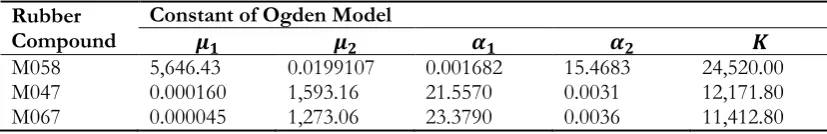
Table 3. The constants of Ogden model for each rubber compound.
Rubber
Compound Constant of Ogden Model 𝝁𝟏 𝝁𝟐 𝜶𝟏 𝜶𝟐 𝑲
[image:8.595.74.522.452.535.2] [image:8.595.90.504.582.649.2](a) M058
(b) M047
(c) M067
[image:9.595.182.414.79.697.2]M058 M047 M067
(a)
(b)
[image:10.595.71.536.101.361.2](a) M058
(b) M047
(c) M067
[image:11.595.177.412.89.709.2]4.0kN 8.0kN 12.0kN
(a) Von Mises Stress
(b) Vertical Displacement
[image:12.595.76.537.89.667.2](a) 4.0 kN
(b) 8.0 kN
[image:13.595.182.414.77.697.2](c) 12.0 kN
6.
Conclusions
The rubber compounds of the solid tire (KOMACHI) had been carried out to test the stress-strain characteristics. They were three rubber compounds for the internal layer, the middle layer, and the tread layer. The stress-train curve of rubber compounds was fitted with six constitutive models which were comprised of the 2nd order polynomial, 3rd order polynomial, Mooney-Rivlin, Yeoh, Arruda-Boyce, and
Ogden model. The Ogden model was the best fitting model with the stress-strain curve for all rubber compounds. It was precisely shown the R2 of 0.990, 0.988 and 0.989 for the internal, middle and tread layer,
respectively. The six constitutive models were implemented with FEM for simulation of the compression test on a cylindrical specimen. The vertical displacement which increased following the compressive load was carried out to compare with the simulation results. The compressive load vs. vertical displacement curves were nonlinear increase. The specimen model which was defined the material model as the Ogden model had a very good agreement with the experimental data. It had an error of 7.35%, 8.03% and 8.13% for implementation in the internal layer, middle layer, and tread layer, respectively.
The KOMACHI solid tires were performed the compression test. The three compressive loads were specified which were comprised of 4.0, 8.0 and 12.0 kN. The FEM were employed to create the solid tire model. The tetrahedral and hexagonal elements were used to model the solid tire. The tire layers were assigned the Ogden model for the material properties; therefore, each layer was different constant values. The solid tire model was tested with the compressive loads regarding to the physical experiment. The simulation results were good agreement with the experimental results. The vertical displacement of solid tire was nonlinear increase by the increasing of compressive load. The layers of solid tire were different deformation. The internal layer was harder than other layers; therefore, it was rid of deformation. The tread layer was soft as same as the middle layer then it was distinctly investigated deformation at the contact point between tread and floor. The solid tire simulation for the compression test had a little error when it was compared with the physical experiment. The average error of the FEM was 8.49%. The finite element model of solid tire was satisfied to analyze the tire performance. It was found that the Ogden model was suitable for the material property of solid tire components which were three rubber layers of KOMACHI solid tires. The solid tire model which was developed in this research will be advantage for design and development of the new solid tire for manufacturing in the further work.
Acknowledgement
This research was funded by The Thailand Research Fund (TRF) and V. S. Industry Tyres Co., Ltd under Research and Researchers for Industries (RRI) Master Scholarship (MSD59I0010). This work was also supported by the 60th year supreme reign of His Majesty King Bhumibol Adulyadej Scholarship, granted by
the faculty of graduate studies academic year 2016, Mahidol University.
References
[1] S. Palanivelu, K. V. N. Rao, and K. K. Ramarathnam, “Determination of rolling tyre model parameters using finite element techniques and operational model analysis,” Mech. Syst. Signal PR., vol. 64-65, pp. 385-402, Dec. 2015.
[2] S. L. Sokolov, “Calculation of the stress-strain state of pneumatic tires by the finite element method,”
Journal Machinery Manufacture and Reliability, vol. 36, no. 1, pp. 57-63, Jan. 2007.
[3] H. Guo, C. Bastien, M. Blundell, and G. Wood, “Development of detailed aircraft tyre finite element model for safety assessment,” Mater. Design, vol. 53, pp. 902-909, Jan. 2014.
[4] A. Mohsenimanesh, S. M. Ward, and M. D. Gilchrist, “Stress analysis of multi-laminated tractor tyre using non-linear 3D finite element analysis,” Mater. Design, vol. 30, no. 4, pp. 1124-1132, Apr. 2009. [5] V. Alkan, S. M. Karamihas, and G. Anlas, “Finite element modeling of static tire enveloping
characteristics,” Int. J. Auto. Tech. Kor., vol. 12, no. 4, pp. 529-535, Aug. 2011.
[6] X. Yang and O. A. Olatunbosun, “Optimization of reinforcement turn-up effect on tyre durability and operating characteristic for racing tyre design,”Mater. Design, vol. 35, pp. 798-809, Mar. 2012.
[8] P. Baranowski, J. Malachowski, and L. Mazurkiewicz, “Numerical and experimental testing of vehicle tyre under impulse loading conditions,” Int. J. Mech. Sci., vol. 106, pp. 346-356, Feb. 2016.
[9] P. Baranowski, J. Malachowski, J. Janiszewski, and J. Wekezer, “Detail tyre FE modelling with multistage validation for dynamic analysis,” Mater. Design, vol. 96, no. 15, pp. 68-79, Apr. 2016.
[10] C. Wei and O. A. Olatunbosun, “The effect of tyre material and structure properties on relaxation length using finite element method,” Mater. Design, vol. 102, no. 15, pp. 14-20, Jul. 2016.
[11] C. Wei and O.A. Olatunbosun, “Transient dynamic behavior of finite element tire traversing obstacles with different heights,” J. Terramechanics, vol. 56, pp. 1-16, Dec. 2014.
[12] Standard test methods for rubber properties in compression, ASTM D575, American Society for Testing and
Materials, 1991.
[13] Standard test methods for rubber properties–Vulcanization using rotorless cure meters, ASTM D5289, American
Society for Testing and Materials, 2001.
[14] G. Hu, P. Zhang, G. Wang, M. Zhang, and M. Li, “The influence of rubber material on sealing performance of paking element in compression packer,” J. Nat. Gas Sci. Eng., vol. 38, pp. 120-138, Feb. 2017.
[15] M. Sesso, G. Chiappini, M. Rossi, E. Mancini, L. Cortese, and D. Amodio, “Structural analysis of an elastomeric below seal in unsteady conditions: simulations and experiments,” Int. J. Mech.Mater. Des., vol. 13, no. 3, pp. 347-362, Sep. 2017.
[16] Y. F. Wu, H. Wang, A. Q. Li, D. M. Feng, B. Sha, and Y. P. Zhang, “Explicit finite element analysis and experimental verification of sliding lead rubber bearing,” J. Zhejing Univ-Sci A (Appl. Phys. & Eng.), vol. 18, no. 5, pp. 363-376, May. 2017.
[17] C. Zhou, J. Zheng, C. Gu, Y, Zhao, and P. Liu, “Sealing performance analysis of rubber O-ring in high-pressure gaseous hydrogen based on finite element method,” Int. J. Hydrogen Energ, vol. 42, no. 16, pp. 11996-12004, Apr. 2017.
[18] C. O. Horgan and J. G. Morphy, “Compression tests and constitutive models for the slight compressibility of elastic rubber-like materials,” Int. J. Eng. Sci., vol. 47, no. 11-12, pp. 1232-1239, Nov.-Dec. 2009.
[19] O. H. Yeoh, and P. D. Fleming, “A new attempt to reconcile the statistical and phenomenological theories of rubber elasticity,” J. Polym. Sci. Pol. Phys., vol. 35, no. 12, pp. 1919-1931, Sep. 1997.
[20] E. M. Arruda and M. C. Boyce, “A three-dimensional constitutive model for the large stretch behavior of rubber elastic materials,” Journal of Mechanics and Physics of Solids, vol. 41, no. 2, pp. 389-412, Feb. 1993.
[21] R. W. Ogden, “Large deformation isotropic elasticity: on the correlation of theory and experiment for incompressible rubberlike solids,” in Proc. R. Soc. Lond. A., vol. 326, no. 1567, pp. 565-584, Feb. 1972. [22] R. W. Ogden, G. Saccomandy, and I. Sgura, “Fitting hyperelastic models to experimental data,”Comput.
Mech., vol. 34, no. 6, pp. 484-502, Nov. 2004.
[23] K. J. Bathe, “Finite element nonlinear analysis in solid and structural mechanics,” in Finite Element