Aircraft turbine engine control systems development:
Historical
Perspective
Jackson Lutambo
1, Jiqiang Wang
1, 2, Hong Yue
3, Georgi Dimirovsky
41. Jiangsu Province Key Laboratory of Aerospace Power System, Nanjing Universityof Aeronautics and Astronautics,Nanjing,210016, China
2. AVIC Shenyang Engine Design & Research Institute, Shenyang 110015, China 3. The University of Strathclyde, Glasgow, UK
4. Dogus University of Istanbul, Istanbul, Turkey
E-mail: [email protected], [email protected], [email protected], [email protected]
Abstract: This paper describes the development of aircraft turbine engine control systems from the historical point of view to the present. With the increasing emphasis on aircraft safety, enhanced performance, and affordability, as well as the need to reduce the environmental effect caused by aircraft, there are many new challenges being faced by the designers of aircraft propulsion systems. The paper provides an overview of the various technological development activities in aircraft engine control and diagnostics, both current and some accomplished in the recent past. The motivations for each of the research efforts, the research approach, technical challenges, and the key progress to date are summarized.
Keywords: Control system, Gas Turbine Engine, Hydromechanical System, FullAuthority Digital Electronic Control (FADEC),
Digital Electronic Engine Control (DEEC)
1.0 Introduction
The goal of any engine control system is to allow the engine to perform at maximum efficiency for a given condition. The complexity of this task is proportional to the complexity of the engine. Historically, jet engines have been controlled by hydromechanical control systems which consisted of simple mechanical linkages controlled by the pilot. As the engines have become more complex, with more control signals and higher demands on performance and functionality, electronic control systems have been introduced [1].The modern aero-engine used today for aircraft propulsion has evolved into its current form over the past 60 years, and Control technology has played a critical role in improving the performance, reliability, operating lifetime, and safety. Today all modern aero engines are controlled by Full Authority Digital Electronic control (FADEC) systems, or a combination of electronic and hydromechanical systems. The control functions implemented in many of these systems have not changed that much. The principle of using only fuel flow for speed control and limit the amount during transients, as in the first hydromechanical systems is
still the main control strategy in many systems. Other control signals are often open loop scheduled, or used only for limiting engine parameters. Interaction among the various control loops are most often neglected in the design of control law and the resulting problems are solved by a large number of fixes and special cases andthis still works satisfactorily for the engines used today [1].
The trend towards increasingly complex jet engines will undoubtedly continue in order to meet increasing demands on performance, fuel consumption and functionality. The interaction between the engine and aircraft systems will also increase, with mission-specific control and with the control of thrust direction. To utilize the potential of these engines, it is also necessary to use more advanced control concepts than conventionally used today. The trend is towards control concepts often referred to as ‘smart engines’ andthe multivariable controllers are most often the core of these advanced control concepts[1]. This paper discuss some of the developments which have taken place since the introduction of turbine engine as the main propulsion device on the aircraft with regards to the control systems.
2.0 The birth ofTurbine Engine Control
Systems
The 1930’s saw the evolution of independent design and development work on gas turbine engines in Great Britain and Germany. Sir Frank Whittle patented his gas turbine engine in 1930 and after several years of development, a version of the same † We wish to acknowledge the support of the Natural
Science Foundation of Jiangsu Province (No. BK20140829);
Jiangsu Postdoctoral Science Foundation (No.1401017B); and
the Scottish Government which funded this project through the
Royal Society of Edinburgh in partnership with the NNSFC; Fund
was first installed on an aircraft in 1941 [2]. Hans von Ohain had a patent for his engine in Germany in 1936 and the first flight with this engine had taken place in 1939 [2]. The first gas turbine engine developed by Whittle [2] had a simple throttle lever that controlled fuel flow into the engine. To accommodate the functional requirements when fitted on aircraft, design of fuel control system had to take into account effects of altitude, temperature and forward speed [3]. At the same time, continued requirements to improve gas turbine engine performance, production and life limiting processes had their impacts on gas turbine technologies [3]. In the 1950s, aircraft engine control systems were based on hydromechanical technologies and were complex artifacts. They encompassed a large number of components and subcomponents, and they were application-specific, such that a change in the design of the engine required a change in the design of the control system. Hydromechanical control systems reached a technological ceiling in a relatively short time. The maturity of the technology enabled engineers to understand, articulate, and modularize the interfaces between the engine and the hydromechanical control system. Furthermore, performance improvements derived primarily from operational experience rather than from scientific or technological breakthroughs had their impacts on turbine technology[4]. In the mature stage of development reached in the 1970s, hydromechanical control systems were characterized by a relatively low rate of technological change and increasingly predictable interdependencies with the other components. Although hydromechanical control systems had achieved relatively high reliability, they displayed limitations. Higher-thrustengines that were being developed during the 1970s were characterized by a larger number of parameters that needed accurate measurement and computation. In particular, the increasing bypass ratio (i.e., the ratio of mass flow through the fan or bypass duct to that through the core) of the newly developed engines posed several problems for the calculation and control of thrust during engine operation. To avoid over-boost and over-temperature, more frequent adjustmentsof the power lever were required, and traditional hydromechanical control systems could not manage these problems. The complexity of thrust calculations, the high accuracy andquick-response time required, and the fact that most parameters (turbine temperature, fan speed, altitude) were available in electronic form therefore rendered digital electronics more suitable for control systems [5]. In order to introduce redundancy and enable greater safety in operation, certain electric supervisory devices and limiter controls were introduced. The subsequent
growth of electronics and computer technology with their enhanced reliability enabled full authority digital electronics to be used. A historical perspective of the advancement in control technologies for aircraft gas turbine engines related to the US scenario has been outlined in [6]. A simple engine speed-power lever angle loop is illustrated in Figure 1.
[image:2.595.319.523.208.257.2]PLA – Power Lever Angle, FF – Fuel Flow, N – Rotational Speed, metering valve, Nd – N-Demand, MVd – MV-demand, Nact – N-actual, MVact – MV-actual
Figure 1: Typical engine speed-Power Lever Angle (PLA) loop
3.0 Hydromechanical Fuel Control
cam was developed with a notched surface that facilitated scheduled fuel control and variable stator vane revolution. Increased precision and miniaturization enabled the utilization of these systems in aircraft jet engines. However, the notched surface of three-dimensional cams did not facilitate the fine-tuning of the preset fuel schedule, and controlling it based on exhaust gas temperatures was difficult [9].
4.0 Digital Electronic Engine Control (DEEC)
Mechanical control systems when integrated with newer turbine engines suffered from the inherent limitations of tuning and adjustment beyond their physical defined limits. The electronic software based control thus offered distinct advantages, such as: Ease of adjustments of transient schedules/limiter schedules/Magnitude changes and slope changes in schedules/Changes in control logics. All these could be accomplished by changes of software build of the embedded controller in the electronic system [10]. Based on the redundancy management architecture, safe operation even with one lane nonoperational could be demonstrated. At the start of the gas turbine era, there had been only one control variable, namely, fuel flow. With advances in gas turbine cycles and technologies, the need for a greater number of control variables had slowly evolved over the decades. The introduction of digital electronics progressively enlarged the role, importance, and functions of the engine control system as well as its interfaces with the other engine components and the airframe. The radical Technological shift led to a functional shift as Digital electronics is a fast moving technology. This high rate of advance enabled the embodiment in the control system of a large and increasing number of functionalities previously carried out by the pilot. The digital control system became the brain of the engine. In addition, digital control systems potentialities created new sets of technological imbalances between the control system and the engine power system. Although digital control systems interacted with, in fact, controlled a higher and enlarging number of engine components, these interdependencies were governed by the so called interface software. Due to this software component, digital control systems were not application-specific, and hardware and software modules could be reused in different applications. Digital control systems therefore exhibited predictable product systemic interdependencies, since such interdependencies were managed by the interface software [4].
DEEC was initially tested and evaluated by the NASA Dryden Flight Research Center from 1981 to 1983 in a joint endeavor with engine manufacturer Pratt and Whitney, the U.S. Air Force, and NASA's
Lewis Research Center (now the NASA Glenn Research Center) [11].The DEEC was developed for the Pratt and Whitney F100 turbofan engine, but its technology is now incorporated on other engine models. The DEEC replaced the F100 test engine's standard control system and had full control authority over a variety of engine functions.
Development of the DEEC is looked upon asa milestone in propulsion control, and a major transition from hydro mechanical to digital control.Benefits of the system are substantial and include reduced operating and maintenance costs, plus major boosts in engine performance and extended engine life[11].
5.0 Full Authority Digital Electronic Control (FADEC)
Full authority digital engine control (FADEC) is a system consisting of a digital computer, called an electronic engine controller (EEC) or engine control unit (ECU) and its related accessories that control all aspects of aircraft engine performance. FADECs have been produced for both piston and jet engines.True full authority digital engine controls have no form of manual override available, placing full authority over the operating parameters of the engine in the hands of the computer. If a total FADEC failure occurs, the engine fails. If the engine is controlled digitally and electronically but allows for manual override, it is considered solely an EEC or ECU. An EEC, though a component of a FADEC, is not by itself FADEC. When standing alone, the EEC makes all of the decisions until the pilot wishes to intervene.
identical all engin monitors subsystem fault tole in opera efficiency emergenc but limita no means
6.0 Adv
With the Synthesis Isolation there wa engine co grew sign of techn NASA pr research how to a control a and perfo and actu thus prov research. technolog incorpora in the FA engine c performa not be performa emerge. investiga enabled aviation control challengi environm accompli described 6.1 Integ
In the m military f aircraft such as s and high flight/pro order to reasonab The maj integrated (2) cent
digital chann e functions w a variety of ms and related erant engine c
ation are co y. Maximum cy situations i ations can’t b s of manually
vanced Engin
e success of th s (MVCS)
and Accom as renewed in ontrol technol nificantly dur nology develo
rograms and i programs. T apply emergin approaches to ormance for e ators on the viding an opp
The continu gy also op ating more co ADECs. The
components ance througho
constrained ance at other There was ate nontraditi through adv safety, and architectures ing goals of in mental impac ishments in th d.
grated Flight/
mid-1980s to fighter/tactica with new/enh short takeoff h-angle-of-atta opulsion contr obtain thes le pilot workl ajor design
d airframe/eng tralized cont
nels. Each cha without restrict f data coming d aircraft syste control. In flig onstantly ma m thrust is if the throttle i be exceeded; th
overriding th
ne Control
he F100 Mul and Adva mmodation (A
nterest at GR logies[11]. Th ring the 1990s opment effor in collaboratio The research
ng multivariab provide impro engines. The n engines conti portunity for a ued advancem pened the omplexity into
idea of using to maximize out the operati to accept than design s additional ional uses vanced contr
to start fo that will ncreased effic ct. Some of he mid-1990s
/Propulsion C
o 1990s, the al aircraft desig
hanced mane and vertical ack performan
rol (IFPC) sys se enhanced
oad.
steps are (1 gine models f trol design,
annel may pro tion. FADEC g from the en ems, providin ght, small cha ade to main s available is advanced to
he flight crew e FADEC
ltivariable Co anced Detec ADIA) progr RC in investin he Controls g s with a multi rts under var on with Air F emphasis wa ble and intelli oved function number of sen inued to incre advanced con ment in comp
possibilities o the control l g active contro
e the achiev ing envelope,
the subopt points, bega opportunity of the eng rols, to incr rmulating en help meet iency and red f the signif to early 2000
Control
e trend in fu gn was toward euver capabil
landing (STO nce. An integr stem is require
capabilities
1) generation for control de
considering ovide also ngine g for anges ntain for o full, w has ntrol ction, rams, ng in group itude rious Force as on igent nality nsors ease, ntrols puter of logic ol of vable , and timal an to y to gines, rease ngine the duced ficant s are uture ds lities OVL) rated ed in with
n of sign; the
[image:4.595.331.524.490.698.2]airframe and (3) partitioni separate airf Operational scheduling o nonlinear des for operation assembly and for IFPC desi the landing a [12]. During transitions fr aerodynamic system gene technologies multivariable developed as and Airfram study [12]. T problem fram using H-infin of thumb for the design pr partitioning a hierarchical scheme for c robustness control desig designing int which guara single-actuato shows applic the propulsio design (Matte
Figure 4.—Inte (from Matterna
engine system ing of the c frame and e flight enve of the partit sign such as i nal safety; and
d evaluation. ign for a conc approach to ho g this phase t
rom forces an control effec erated forces
that are rel e control d
part of the M me Control IM hese are (1) a mework for ro
nity control de r selecting var rocedure; (2) a centralized c
subsystem co controller sche
properties gns; and (4) tegrator wind-antees closed-or saturation. ation of the o on control po ern andGarg 1
egrator wind-up and Garg 1992;
m as an integ centralized c engine subco elope expans tioned subco incorporation d (6) full syst The approach ceptual ASTO
over transition the control o nd moments ctors to pure s and mome levant to pra design techn Methodology f
MPAC-based a generic comm
obust control esign techniqu rious frequen
a systematic controller into ontrollers; (3) eduling, whic of centraliz ) a modified -up protection -loop system An example optimized IWP
rtion of the S 1992) is shown
p protection for ; courtesy NAS
grated system ontroller into ontrollers; (4) sion through ontrollers; (5) of limit logic tem controller h was applied OVL aircraft in n flight phase of the aircraft generated by ely propulsion ents. Various actical use of niques were for Propulsion IFPC design mand tracking law synthesis ues with rules ncy weights in procedure for decentralized ) a simplified h exploits the zed/partitioned d scheme for n (IWP) gains m stability for
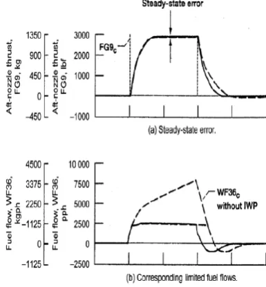
e result which P technique to STOVL IFPC n in Figure 4.
Shown are the responses of the aft nozzle thrust (FG9) to a step command and the corresponding fuel flow (WF36) requirement with and without the IWP. Without IWP (dashed lines), when the fuel flow limit is encountered, the fuel flow command continues to grow because of integrator wind up. As the FG9 command is reduced to zero, the integrator takes time to wind down and the FG9 response is degraded. With IWP active (solid lines), the fuel flow command tracks the fuel flow limit, and good FG9 tracking performance is obtained when the step command is removed. Although IMPAC methodology was successfully demonstrated by NASA, its application to current and future aircraft configurations was perceived as too complex during industry evaluation. However, the technologies developed for practical application of multivariable control design techniques were perceived to be of value by the industry and were transferred to industry through joint studies as documented in [13].
6.2 Intelligent Life Extending Control
With the desire to reduce engine operating cost, the industry is interested in developing technologies that will allow the engine and its components to operate (remain on wing) longer, thus increasing the time between engine overhauls. How the engine is controlled has a significant impact on the life of the components. Typically, the propulsion system control design engineer attempts to get the maximum performance out of the system while maintaining safe operation. Recent studies have shown that small changes in engine operating parameters, such as turbine inlet temperature, can have a significant impact on the damage accrued by engine components while having little to no effect on engine performance. GRC developed the concept of Life Extending Control where the engine control system is designed to achieve the desired performance while minimizing the damage accrued in engine components, hence maximizing the usable engine life.
6.3 High Stability Engine Control (HISTEC)
For aircraft engines, a safety margin, called the “stability margin,” is built into the operation of the engine to prevent inception of fan/compressor stall due to inlet distortions caused by aircraft maneuvers or atmospheric disturbances. This stability margin results in a performance penalty being paid even at low distortion operating conditions such as cruise. Engine companies have estimated that being able to actively control the engine to safely maintain low stability margins under such low distortion operating conditions can result in reduction of 2 percent or more in specific fuel consumption.
6.4 Active Stall Control
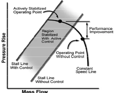
[image:5.595.320.519.475.637.2]The peak efficiency operating point of a turbine engine compressor is typically very near the compressor stall line as shown in Figure 5. In order to prevent catastrophic stall from occurring during large transients, the engine is operated with a sufficiently large safety margin. If the compressor can be safely operated closer to the designed compressor peak efficiency, then it will result in increased engine efficiency leading to significant savings in aircraft fuel costs. Even if compressor efficiency drops, cycle efficiency can be higher at higher overall pressure ratios. As shown in Figure 5, the compressor stall line can be moved up through active control thus allowing safe operation at peak efficiencies. Under the active stall control concept, however, the engine stall line is moved up through some active flow control. The active stall control is obtained by sensing pressure changes at the inlet face of the compressor, which will indicate flow distortion that is the precursor to stall, and activating high bandwidth flow valves located around the circumference of the compressor that blow high-pressure air to counter the flow distortion before it builds up to stall. The challenges for implementation of active stall control are developing accurate models of the stall phenomenon that can be used for control design, developing high-bandwidth (on the order of 500 Hz) actuators for controlling flow valves, and understanding the effectiveness of different actuating schemes for stall control.
Figure 5.—Active stall control extends operating region forengines (image courtesy of NASA).
6.5 Current Research
control technologies to replace the Full Authority Digital Engine Control (FADEC) system currently used by turbine engines is being undertaken. The intent was to investigate a solution which reduces energy consumption and increases efficiency of turbine engine operations. Active component control approaches such as active combustion control and active flow control for compression systems, and distributed engine control architecture are critical enabling technologies to meet the challenging goals of reducing aircraft engine emissions. Integrated control of inlet and engine systems is key for achieving safety and performance goals of high speed propulsion system. Intelligent propulsion control and diagnostics can significantly increase aircraft safety and improve operational reliability of space launch systems.All these are under study by various groups and individuals to improve turbine engine controls.
7.0 Conclusion
In conclusion, this paper provided a broad overview of the state-of-the-art of engine control, some significant past development of the engine controls that have resulted in increased efficiency and performance of aircraft engines, and some recent accomplishments where elements of the technologies developed can be expected to find their way into future aircraft engines.
References
[1] MelkerHarefors (1996). Multivariable Control Design For a Jet Engine: Volvo Aero Corporation, S-46181 Trollhattan, Sweden.
[2] Flack, R.D., Fundamentals of Jet Propulsion and Applications, Cambridge University Press, 2005.
[3] Balakrishnan S.R. (2013) Control System Development Experience for Aero Gas Turbine Demonstrator Engines. Gas Turbine Research Establishment, DRDO, Bangalore, India
[4] Prencipe, A (2000). Breadth and depth of technological capabilities in complex product systems: The
case of the aircraft engine control system." Research Policy, 29: 895-911.
[5] Griffiths, D. M., and R. D. Powell. The use of digital control for complex power plant management, AGARD Conference Proceedings N. 151, Power Plants Controls for Aircraft Gas Turbine Engines, Ustaoset, Norway.September.
[6] Link C Jaw and Sanjay Garg, Propulsion Control Technology Development in the United States, NASA/TM-2005-213978.
[7] Otto, E. W., and Taylor, B. L., III, (1950). “Dynamics of a turbojet engine considered as a quasi-static system.” NACA Report 1011, NACA, Washington, DC,
[8] Ketchum, J. R., and Craig, R. T. (1952). Simulation of linearized dynamics of gas-turbine engines. TN–2826, NACA, Cleveland, OH,
[9] Brusoni, S., Prencipe, A., &Pavitt, K. (2001). Knowledge specialization, organizational coupling, and the boundaries of the firm: Why do firms know more than they make? Administrative Science Quarterly, 46, 597–621.
[10] Balakrishnan, S.R., Evolution of control systems for Aircraft Gas Turbine Engine under development, J. AeSI, 48(1) (1996), 94-104.
[11] Sanjay Garg (2013) Aircraft Turbine Engine Control Research at NASA Glenn Research Center. Glenn Research Center, Cleveland, Ohio USA
[12] Garg, S., and Mattern, D. L. (1994). “Application of an integrated methodology for propulsion and airframe control design to a STOVL aircraft.” 94–3611, AIAA, Reston, VA.
[13] Watts, S. R., and Garg, S. (1995). “A comparison of multivariable control design techniques for a turbofan engine control.” ASME 40th Gas Turbine and Aeroengine Congress and Exposition, Houston, TX.
[14] DeCastro, J. A., Litt, J. S., and Frederick, D. K. (2008). “A modular aero-propulsion system simulation of a large commercial aircraft engine,” 2008–4579, American Institute of Aeronautics and Astronautics (AIAA), Reston, VA.
[15] Flack, R.D., Fundamentals of Jet Propulsion and Applications, Cambridge University Press, 2005.