University of Windsor University of Windsor
Scholarship at UWindsor
Scholarship at UWindsor
Electronic Theses and Dissertations Theses, Dissertations, and Major Papers
11-28-2018
Model-Guided Data-Driven Optimization and Control for Internal
Model-Guided Data-Driven Optimization and Control for Internal
Combustion Engine Systems
Combustion Engine Systems
Qingyuan TanUniversity of Windsor
Follow this and additional works at: https://scholar.uwindsor.ca/etd
Recommended Citation Recommended Citation
Tan, Qingyuan, "Model-Guided Data-Driven Optimization and Control for Internal Combustion Engine Systems" (2018). Electronic Theses and Dissertations. 7625.
https://scholar.uwindsor.ca/etd/7625
This online database contains the full-text of PhD dissertations and Masters’ theses of University of Windsor students from 1954 forward. These documents are made available for personal study and research purposes only, in accordance with the Canadian Copyright Act and the Creative Commons license—CC BY-NC-ND (Attribution, Non-Commercial, No Derivative Works). Under this license, works must always be attributed to the copyright holder (original author), cannot be used for any commercial purposes, and may not be altered. Any other use would require the permission of the copyright holder. Students may inquire about withdrawing their dissertation and/or thesis from this database. For additional inquiries, please contact the repository administrator via email
Model-Guided Data-Driven Optimization and Control for
Internal Combustion Engine Systems
By
Qingyuan Tan
A Dissertation
Submitted to the Faculty of Graduate Studies
through the Department of Electrical and Computer Engineering
in Partial Fulfillment of the Requirements for
the Degree of Doctor of Philosophy
at the University of Windsor
Windsor, Ontario, Canada
2018
Model-Guided Data-Driven Optimization and Control for
Internal Combustion Engine Systems
by
Qingyuan Tan
APPROVED BY:
______________________________________ C.R. Koch, External Examiner
University of Alberta
______________________________________________ J. Tjong,
Department of Mechanical, Automotive & Materials Engineering
______________________________________________ M. Saif,
Department of Electrical and Computer Engineering
______________________________________________ B. Shahrrava,
Department of Electrical and Computer Engineering
______________________________________________ X. Chen, Co-Advisor
Department of Electrical and Computer Engineering
______________________________________________ M. Zheng, Co-Advisor
Department of Mechanical, Automotive & Materials Engineering
iii
DECLARATION OF ORIGINALITY
I hereby certify that I am the sole author of this thesis and that no part of this thesis has
been published or submitted for publication.
I certify that, to the best of my knowledge, my thesis does not infringe upon anyone’s
copyright nor violate any proprietary rights and that any ideas, techniques, quotations, or
any other material from the work of other people included in my thesis, published or
otherwise, are fully acknowledged in accordance with the standard referencing practices.
Furthermore, to the extent that I have included copyrighted material that surpasses the
bounds of fair dealing within the meaning of the Canada Copyright Act, I certify that I
have obtained written permission from the copyright owner(s) to include such material(s)
in my thesis and have included copies of such copyright clearances to my appendix.
I declare that this is a true copy of my thesis, including any final revisions, as approved
by my thesis committee and the Graduate Studies office and that this thesis has not been
iv
ABSTRACT
The incorporation of electronic components into modern Internal Combustion, IC, engine
systems have facilitated the reduction of fuel consumption and emission from IC engine
operations. As more mechanical functions are being replaced by electric or electronic
devices, the IC engine systems are becoming more complex in structure. Sophisticated
control strategies are called in to help the engine systems meet the drivability demands
and to comply with the emission regulations.
Different model-based or data-driven algorithms have been applied to the optimization
and control of IC engine systems. For the conventional model-based algorithms, the
accuracy of the applied system models has a crucial impact on the quality of the feedback
system performance. With computable analytic solutions and a good estimation of the
real physical processes, the model-based control embedded systems are able to achieve
good transient performances. However, the analytic solutions of some nonlinear models
are difficult to obtain. Even if the solutions are available, because of the presence of
unavoidable modeling uncertainties, the model-based controllers are designed
conservatively.
The data-driven control algorithms, on the other hand, are the strategies that rely solely
on the relationships between the control input and the measured system output. By
utilizing the measurement only, data-driven algorithms require no prior-information of
the system. The algorithms do not need system models for the development of the
controllers. Data-driven algorithms are good alternatives for solving optimization
problems when the construction of accurate models of the systems are difficult, costly, or
time-consuming. Though robust, because of the lack of system knowledge, data-driven
algorithms constantly suffer from slow convergence during optimization. Moreover, the
demand for readily available measurement also makes the algorithms, if not impossible,
difficult to foresee and prevent degradation of system performance.
In this dissertation, the Model-Guided Data-Driven, MGDD, algorithms are proposed and
applied to the optimization and control of systems related to IC engine operations.
Compared to the conventional model-based algorithms, the proposed methods have
v
knowledge provided by the models become guidance for the data-driven algorithms. As a
result, the transient performance of conventional data-driven optimization is improved.
By adjusting the signal flow between the system models and the data-driven algorithms,
different MGDD algorithms are proposed for different applications.
Finally, simulations and experimental results on the optimization of injection timing for a
Compression Ignition, CI, engine and the control of an Electronic Throttle Body, ETB,
are provided in this work to evaluate the effectiveness of the proposed MGDD algorithms.
Keywords: Model-guided, data-driven, optimization, feedback, IC engine, experiment,
vi
DEDICATION
To mom and dad:
It's impossible to thank you adequately for everything you've done, from loving
me unconditionally to raising me as a person of integrity. You have instilled virtues and
taught me how to celebrate and embrace life. I could not have asked for better parents or
vii
ACKNOWLEDGMENTS
With great honor, I am sincerely grateful to my supervisors, Dr. Xiang Chen and Dr.
Ming Zheng, for their support and guidance throughout my Ph.D. studies at the
University of Windsor. Their wisdom and enthusiasms for research have inspired me to
face every challenge encountered throughout the development of this dissertation.
Without the encouragement and guidance from them, the completion of this work would
have been impossible.
I have received enormous support from Dr. Ying Tan from the University of Melbourne
and my dear colleagues at the University of Windsor during the entire course of my Ph.D.
study. I feel very grateful and would like to express my deepest appreciation to Dr.
Meiping Wang, Dr. Prasad Divekar, Dr. Ruili Dong, Dr. Shui Yu, Dr. Xuebo Zhang, Dr.
Xiao Yu, Dr. Tongyang Gao, Dr. Xiaoye Han, Dr. Tadonori Yanai, Dr. Marko Jeftic, Dr.
Shouvik Dev, Zhenyi Yang, Mark Ives, Geraint Bryden, Christopher Aversa, Hua Zhu,
Navjot Sandhu, Divyanshu Purohit, Simon Leblanc and Linyan Wang.
I am also grateful for the support from the University of Windsor, AUTO 21, Canada
Research Chair Program, Canada Foundation of Innovation, Ontario Innovation Trust,
Natural Sciences and Engineering Research Council of Canada.
Qingyuan Tan
Windsor, Ontario, Canada
viii
TABLE OF CONTENTS
DECLARATION OF ORIGINALITY ... iii
ABSTRACT ... iv
DEDICATION ... vi
ACKNOWLEDGMENTS ... vii
LIST OF TABLES ... xi
LIST OF FIGURES ... xii
NOMENCLATURE ...xv
CHAPTER 1. INTRODUCTION ...1
1.1 Model-Based Optimization and Control ...1
1.2 Data-Driven Optimization and Control ...4
1.3 Scope of Work ...5
1.4 Dissertation Significance ...6
1.5 Dissertation Outline ...7
CHAPTER 2. OPTIMIZATION OF INTERNAL COMBUSTION ENGINE SYSTEMS AND ELECTRONIC THROTTLE CONTROL ...9
2.1 Optimization of Internal Combustion Engine Systems ...9
2.1.1 Design of Experiments Based Optimization ...9
2.1.2 Data-Driven Based Optimization ...12
2.1.3 Model for a Compression Ignition Engine ...13
2.2 Electronic Throttle Control...19
2.2.1 Existing Challenges ...21
2.2.2 Existing Solutions ...22
CHAPTER 3. DATA-DRIVEN OPTIMIZATION AND CONTROL ...25
3.1 Simultaneous Perturbation Stochastic Approximation ...25
3.2 Iterative Learning Control ...28
3.3 Extremum Seeking Control ...30
CHAPTER 4. EXTREMUM SEEKING CONTROL OF INJECTION TIMING IN A COMPRESSION IGNITION ENGINE USING A SOFT SENSOR ...36
4.1 Problem Formulation and Extremum Seeking Control Using a Soft Sensor ...37
4.1.1 Problem Formulation ...37
4.1.2 Extremum Seeking Control Using a Soft Sensor ...40
4.2 Experimental Setup ...41
4.3 Simulation and Experimental Results ...44
ix
4.3.2 Experimental Validation ...51
4.4 Summary ...55
CHAPTER 5. MODEL-GUIDED EXTREMUM SEEKING CONTROL OF INJECTION TIMING IN A COMPRESSION IGNITION ENGINE ...56
5.1 Model-Guided Extremum Seeking Control...56
5.2 Engine Model Validation ...60
5.3 Optimization of Injection Timing in a Compression Ignition Engine ...63
5.3.1 Applicable Conditions for Model-Guided Extremum Seeking Control ...63
5.3.2 Model-Guided Extremum Seeking Control ...64
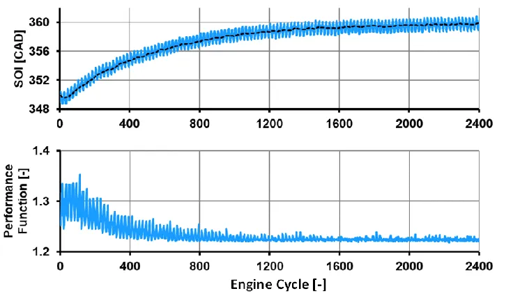
5.3.3 Design of Performance Function ...65
5.3.4 Simulation Study ...66
5.3.5 Experimental Study ...71
5.4 Summary ...75
CHAPTER 6. MODEL-GUIDED EXTREMUM SEEKING CONTROL OF INJECTION TIMING IN A COMPRESSION IGNITION ENGINE WITH ONLINE MODEL CALIBRATION ...76
6.1 Model-Guided Extremum Seeking Control with Online Model Calibration ...76
6.2 Experimental Study ...78
6.2.1 Model Online Calibration ...78
6.2.2 Model-Based Optimization Using Online Calibrated Model ...79
6.2.3 Engine Injection Timing Optimization ...80
6.3 Summary ...81
CHAPTER 7. MODEL-GUIDED DATA-DRIVEN PREDICTIVE CONTROL FOR THE ACTUATION OF AN ELECTRONIC THROTTLE BODY ...83
7.1 Modeling of an Electronic Throttle Body ...84
7.1.1 First-Principle Model ...84
7.1.2 Pseudo-Wiener Model ...89
7.2 Model Identification and Model Validation ...91
7.2.1 Levenberg-Marquardt Algorithm ...92
7.2.2 Experimental Setup...94
7.2.3 Identification and Validation of First-Principle Model ...96
7.2.4 Identification and Validation of Pseudo-Wiener Model ...102
7.3 Model-Guided Data-Driven Predictive Control Strategy ...112
7.4 Experimental Study ...116
x
7.4.2 Experimental Results ...119
7.5 Summary ...129
CHAPTER 8. CONCLUSIONS AND FUTURE PERSPECTIVES ...130
8.1 Conclusions ...130
8.2 Future Perspectives ...131
REFERENCES ...132
xi
LIST OF TABLES
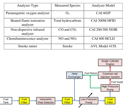
Table 4-1. Gas analyzers ... 43
Table 4-2. Model parameters ... 48
Table 4-3. Summary of test results ... 55
Table 7-1. Parameters for the first-principle ETB model ... 85
Table 7-2. Identified parameters for the first-principle ETB model ... 99
Table 7-3. Identified parameters for the Pseudo-Wiener models ... 109
Table 7-4. MSE for the experiments shown in Figure 7-32 ... 125
xii
LIST OF FIGURES
Figure 1-1. Main contribution ... 7
Figure 1-2. Dissertation outline ... 8
Figure 2-1. The model-based DOE steps ... 11
Figure 2-2. Torque-based throttle opening estimation ... 20
Figure 2-3. Schematic of an ETB ... 21
Figure 2-4. ETB valve opening affected by the flow of air ... 21
Figure 2-5. Rate-dependent characteristics of an ETB system ... 22
Figure 3-1. Structure for perturbation-based ESC ... 31
Figure 4-1. The ESC structure using soft sensor prediction ... 41
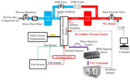
Figure 4-2. Schematic of the single-cylinder research engine platform ... 42
Figure 4-3. Schematic of the fueling system ... 43
Figure 4-4. Working mechanism of the soft sensor ... 45
Figure 4-5. Comparison of steady-state responses among different measurements ... 45
Figure 4-6. Comparison of transient responses between different sensors ... 46
Figure 4-7. Maximum cyclic bulk gas temperature applied for simulation studies ... 47
Figure 4-8. Simulation results: application of feedback with no delay ... 49
Figure 4-9. Simulation results: application of feedback with delay ... 49
Figure 4-10. Simulation results: application of a slower perturbation signal ... 50
Figure 4-11. Test 1: ESC test results for optimizing the thermal efficiency only ... 52
Figure 4-12. Test 2: ESC test starts from a different SOI value ... 53
Figure 4-13. Test 3: ESC test results for optimizing the thermal efficiency and NOx ... 54
Figure 4-14. Test 4: ESC test results using the soft sensor ... 54
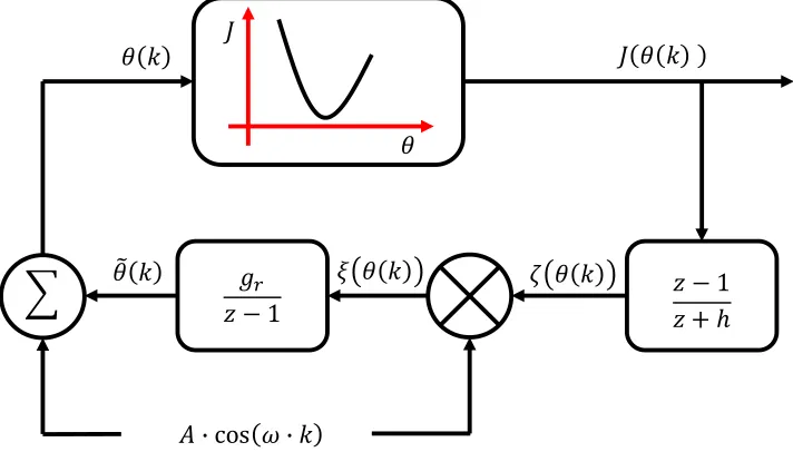
Figure 5-1. Schematic for a model-guided ESC structure ... 60
Figure 5-2. Comparisons between measurement and model output ... 62
Figure 5-3. Model-guided ESC for the optimization of injection timing in a CI engine .. 64
Figure 5-4. Performance function ... 66
Figure 5-5. Modeled rate of heat release ... 67
Figure 5-6. The effect of model accuracy on model-guided ESC ... 67
Figure 5-7. The effect of model accuracy on the model-guided ESC ... 68
xiii
Figure 5-9. Simulation under transient conditions: application of model-guided ESC .... 70
Figure 5-10. The measured relationship between ignition delay and SOI ... 71
Figure 5-11. Engine test results: model-guided ESC ... 72
Figure 5-12. Engine test results: ESC without model guidance ... 73
Figure 5-13. Transient engine test: ESC optimization without model guidance ... 74
Figure 5-14. Transient engine test: Model-guided ESC ... 75
Figure 6-1. Model-guided ESC structure with online model calibration... 77
Figure 6-2. Online model calibration ... 79
Figure 6-3. Gradient descent optimization... 80
Figure 6-4. Engine test results ... 81
Figure 7-1. First-principle ETB model ... 84
Figure 7-2. Coulomb friction ... 86
Figure 7-3. Nonlinear spring ... 87
Figure 7-4. Gear backlash ... 88
Figure 7-5. The Wiener structure model ... 89
Figure 7-6. Schematic of the ETB test setup ... 95
Figure 7-7. Schematic of the steady flow bench ... 95
Figure 7-8. Control signal (blue) and ETB position (red) ... 98
Figure 7-9. ETB actuated above the limp-home ... 99
Figure 7-10. ETB actuated below the limp-home ... 99
Figure 7-11. Parameter identification for the first-principle ETB mode ... 100
Figure 7-12. Identified first-principle ETB model ... 100
Figure 7-13. Model validation ... 101
Figure 7-14. Poor matching between measurement and model output ... 102
Figure 7-15. Excitation signal for model identification: above limp-home position ... 105
Figure 7-16. Identified Pseudo-Wiener model: above limp-home position ... 106
Figure 7-17. Data-driven Pseudo-Wiener model: above limp-home position ... 107
Figure 7-18. Excitation signal for model identification: below limp-home position ... 108
Figure 7-19. Data-driven Pseudo-Wiener model: below limp-home position ... 108
Figure 7-20. Validation of the PWA model: without air flow condition ... 110
xiv
Figure 7-22. Validation of the PWB model: without air flow condition ... 112
Figure 7-23. Data-driven ETB model ... 112
Figure 7-24. The MGDD predictive control algorithm ... 113
Figure 7-25. Reference trajectory ... 117
Figure 7-26. Tracking test results: values of the weighting factors are set equal ... 118
Figure 7-27. Tracking test results: values of the weighting factors are set differently ... 119
Figure 7-28. Effect of different performance function designs ... 120
Figure 7-29. Control of ETB under air flow conditions ... 120
Figure 7-30. MGDD control structure using two models ... 121
Figure 7-31. Control of ETB: step reference across the limp-home position ... 122
Figure 7-32. Step tracking comparison: no air flow condition ... 125
Figure 7-33. Step tracking comparison: with air flow condition ... 126
Figure 7-34. Tracking of sinusoidal references: no flow condition ... 127
Figure 7-35. Step tracking comparison: reference crosses the limp-home position ... 128
xv
NOMENCLATURE
Acronym
BBM Black-box model
CAD Crank angle degree
CAN Controller area network
CFD Computational fluid dynamic
CI Compression ignition
DC Direct current
DEM Discrete event model
DI Direct injection
DOC Diesel oxidation catalyst
DOE Design of experiments
DPF Diesel particulate filer
ECU Engine control unit
EGR Exhaust gas recirculation
EPA Environmental protection agency
EMF Electromotive force
ESC Extremum seeking control
ETB Electronic throttle-body
EVO Exhaust valve opening
FPM First-principle model
FPGA Field programmable gate array
GBM Grey-box model
HC Hydrocarbon
HCCI Homogeneous charge compression ignition
IC Internal combustion
IMEP Indicated mean effective pressure
xvi
IVC Intake valve closing
LHV Lower heating value
LMA Levenberg-marquardt algorithm
LNT Lean NOx trap
LUT Look-up table
LTI Linear time-invariant
MGDD Model-guided data-driven
MPC Model predictive control
MSE Mean squared error
MVM Mean value model
NOx Oxides of nitrogen – NO and NO2
PC Personal computer
PID Proportional-integral-derivative
PM Particulate matter
PWA Model that covers the ETB response above the limp-home position
PWB Model that covers the ETB response below the limp-home position
PWM Pulse width modulation
RPM Revolutions per minute
RT Real-time
SMC Sliding model control
SI Spark ignition
SISO Single-input-single-output
SOC Start of combustion
SOI Start of injection
TDC Top dead center
TTL Transistor-transistor logic
UHC Unburned hydrocarbon
xvii VRFT Virtual reference feedback tuning
Symbols
Unit
𝜃 Control input [-]
𝜃∗ Optimum control input [-]
𝜃̂∗ Optimum control input for the model [-]
𝑝 In-cylinder pressure [bar]
𝐽 Performance function [-]
𝑔𝑟 Adaptation gain [-]
𝑧 Forward time shift operator [-]
𝐴 Amplitude of the perturbation signal [-]
𝜔 Frequency of the perturbation signal [rad/s]
𝑢 Global input [-]
𝑦 System output [-]
𝑦̂ Model output [-]
ℛ Set of real numbers [-]
𝑆𝐴 Amplitude of the excitation signal [-]
𝑆𝑜𝑓𝑓 Offset of the excitation signal [-]
𝜑 Engine crank angle [o]
𝜔𝑅𝑃𝑀 Engine speed [RPM]
𝑚𝑓𝑢𝑒𝑙 Cyclic injected fuel mass [𝑚𝑔/𝑐𝑦𝑐𝑙𝑒]
𝑍 Vector of performance output [-]
𝑉 Cylinder volume [L]
𝑙 Connecting rod length [mm]
𝑎 Crank radius [mm]
𝑉𝑠 Cylinder swept volume [L]
𝑉𝑐 Cylinder clearance volume [L]
𝑇 In-cylinder bulk gas temperature [K]
xviii
𝑁𝑖𝑚 Total moles of in-cylinder gas before combustion [mol]
𝑅̅ Universal gas constant [J/mol∙K]
𝑝𝑖𝑛 Intake manifold pressure [kpa]
𝑇𝑖𝑛 Intake temperature [K]
𝜂𝑉 Cylinder volumetric efficiency [-]
𝛿𝑄ℎ𝑟 Rate of heat release [J/CAD]
𝛿𝑄ℎ𝑡 Rate of wall heat transfer [J/CAD]
𝑄ℎ𝑟𝑀𝐴𝑋 Maximum rate of heat release [J/CAD]
𝐴𝑠 Surface area of the combustion chamber [mm2]
𝐵 Cylinder bore [mm]
𝑆𝑝
̅̅̅ Mean piston speed [m/s]
𝑝𝑚𝑜𝑡 Instantaneous motored cylinder pressure [bar]
𝐶1 and 𝐶2 Wall heat transfer coefficient [-]
𝑇𝑤𝑎𝑙𝑙 Combustion chamber wall temperature [K]
𝜑𝐶𝐴50 Crank angle of 50% accumulated heat release [CAD]
𝐿𝐻𝑉 Lower heating value [MJ/𝑘𝑔]
𝜑𝐶𝐷 Combustion duration [CAD]
𝑝𝑖𝑚𝑒 Indicated mean effective pressure [bar]
𝑑𝑝𝑚𝑎𝑥 Peak pressure rise rate [bar/CAD]
𝜆𝑏 and 𝑐 Parameters for gradient descent optimization [-]
𝑥𝑖 Normalized cumulative heat release [-]
𝜎1 and 𝜎2 Coefficients for the Wiebe function [-]
𝜑𝑆𝑂𝐼 Crank angle for the start of fuel injection [CAD]
𝑢𝑑𝑢𝑡𝑦, 𝑢𝑑 Duty cycle of the PWM signal [-]
𝑢𝑑𝑟 Voltage output from the motor driver [V]
𝑢𝑎𝑟𝑚 Voltage applied across the DC motor [V]
𝐾𝑑𝑟 Gain of the motor driver circuit [V]
xix
𝐾𝑚 Torque constant [N∙m/A]
𝐾𝑒𝑚𝑓 Electromotive force constant [V]
𝐾𝑣 Viscous friction gain [N∙m∙s/rad]
𝐾𝑝 Proportional gain [-]
𝐾𝐼 Integral gain [-]
𝐾𝐷 Differential gain [-]
𝑁𝑝 Length of prediction horizon [-]
𝑖𝑎𝑟𝑚 Armature current [A]
𝑇𝑑 Torque caused by Coulomb friction [N∙m]
𝑇𝑚 DC motor torque output [N∙m]
𝑇𝑓 Equivalent friction torque [N∙m]
𝑇𝑠 Equivalent spring torque [N∙m]
𝑇𝑙 Torque output from the gearbox [N∙m]
𝑇𝑝𝑡 Torque caused by the pre-tension of the limp-home spring [N∙m]
𝐽𝑒𝑞 Equivalent inertia of the ETB system [𝑘𝑔∙m2]
𝜔𝑒𝑡𝑏 Angular velocity of the ETB valve plate [rad/s]
𝜃𝐿𝐻 Angular limp-home position [ o]
𝜃𝑒𝑡𝑏 Angular position of the ETB valve plate [ o]
𝜃𝑒𝑡𝑏_𝑚𝑎𝑥 Maximum angular opening position of the ETB valve plate [ o]
𝑘𝑠 Spring gain [N∙m/ o]
𝐶𝑑 Discharge coefficient [-]
𝜌𝑎𝑖𝑟 Density of air at 20 oC [𝑘𝑔/𝑚3]
1
CHAPTER 1.
INTRODUCTION
The optimization and control of the internal combustion engine systems are realized
through either the model-based or the data-driven algorithms. In this chapter, some of the
popular model-based and the data-driven algorithms are reviewed. The advantages, as
well as the limitations of the referred model-based and the data-driven algorithms are
presented. To meet the growing demands of performance improvements for the internal
combustion engine systems, a new category of the optimization/control algorithm is
proposed, i.e. the model-guided data-driven algorithm. The significance of the new
algorithm is also addressed. Finally, the outline of the dissertation is presented.
1.1Model-Based Optimization and Control
With the addition of sensors and electronic actuators, the performance improvements of
the modern Internal Combustion, IC, engine systems have become optimal
multi-objective problems [1-4]. The interconnected dynamics within the IC engine systems
require the precise adjustment and coordination of most accessible system inputs [1-4]. In
general, the applied inputs for an IC engine system are bounded – either physically
bounded, such as the control for an Electronic Throttle Body, ETB, is limited by the rated
specifications of the embedded Direct Current, DC, motor [5-8], or bounded by the
purposes, such as the operating ranges for fuel injection timings in a diesel engine that are
confined for achieving the desired engine performances [7][9 -12].
For most optimization and control problems related to IC engines, one of the many
optimization ‘objectives’ is chosen as the target while the rest of the objectives become
the constraints for the optimization [4]. In the past, suitable model-based algorithms have
been attempted to solve such problems. Zhao et al. have presented a mean-value model
that is linearized at multiple operating points of a diesel engine [10]. The model is then
applied towards diesel engine air-path management using the Model Predictive Control,
MPC. In the study presented by Bengtsson et al. [13], the steady-state nonlinear
relationship between multiple control inputs and the combustion phase of a diesel engine
is estimated by a fourth-order polynomial. The inverse of this nonlinear model is
2
identified model to minimize the fuel consumption and the exhaust emission of the diesel
engine. Isermann et al. have proposed a model-based calibration approach for the
optimization of exhaust emission from a diesel engine using a mean-value engine model
[14].
For the model-based optimization and control approaches, the controller is designed
based on the model parameters with the assumption that the model output can predict the
real system behavior accurately [15]. However, in reality, the modeling process is the
development of mathematical expressions that approximate the system characteristics. In
the approximations, some errors are inevitable - unmodeled system dynamics always
exist within a model. As a result, the closed-loop control system using the model-based
algorithms can be less robust and sometimes unsafe [13][14][16][17].
To keep the advantages of the model-based approaches and, at the same time, improve
the robustness against the existed model uncertainties, robust control strategies have been
developed. For the robust control strategies, the parameters of a system model are applied
for controller design while the output from the controller is conservative in order to
preserve the robustness of the closed-loop system [18][19]. As a result, the transient
performances of the system are, in general, sacrificed [18]. Moreover, because a clear and
practical description of ‘model uncertainty’ is currently not available, the design and
deployment of robust control algorithms in real applications are hurdled [15][19].
Besides the development of control strategies, significant efforts have been made
regarding model accuracy improvement for the emulation of different processes within
IC engine systems. The Computational Fluid Dynamic, CFD, models are the ones that
have the capacity to provide detailed spatially-resolved and temporally-resolved internal
fluid field information for an IC engine system [20]. The CFD models have been utilized
to simulate different air motions and chemical kinetics within Spark Ignition, SI, engines
[21][22]. The air motion, combustion, and emission generation from Compression
Ignition, CI, engines have also been investigated using the CFD models [23][24]. Though
the CFD models can provide high fidelity predictions of the real system responses, it is
impractical to use the CFD models for control-oriented applications because of the
3
On the other hand, control-oriented models are computationally efficient models feasible
for real-time applications [26]. Control-oriented models have been broadly classified into
three categories [8][26][27]:
(1) First-Principle Models or FPMs yield physical insights of the real systems;
(2) Black-Box Models or BBMs rely on experimental data alone and do not require any prior knowledge of the physical principles of a system;
(3) Grey-Box Models or GBMs are partially based on first-principle together with the inclusion of a few tuning parameters. Experimental results are required for the
identification of these parameters.
The FPMs usually contain extensive details of the real system. However, the
development of such models are time-consuming and require a thorough understanding
of the system mechanisms [3][8][26][28]. Moreover, to tune the model parameters for an
FPM hence its output can match the measured system response usually leads to
aggregated model parameters [26]. The numerical values of the aggregated model
parameters usually include the effect of unconsidered and distributed dynamics of the real
system [26]. As a result, the parameters are usually not accurate [26]. From the above
discussion, it is evident that the construction of a valid control-oriented FPM is
challenging.
Compared to the FPMs, the BBMs and the GBMs usually have simple structures but
heavily rely on experimental results for model parameter identification. The system is
excited within its operating ranges by specially designed signals, as the system responses
are recorded [27][29]. By applying different model identification techniques, the model
parameters are determined, thus the model output reproduces the system behavior
[27][29]. However, for nonlinear systems, the identified models usually demonstrate
satisfactory accuracy only within the vicinity of the operating point where the model
parameters are identified [26][27][29]. For an IC engine, this is usually around the
calibrated operating points in the steady-state Look-Up Tables, LUTs [30]. The identified
BBM or GBM models also have limited robustness to disturbances. If the disturbances
have affected the model output to depart significantly from the real measurement [26],
4
From the discussion above, it is apparent that the integrity of the system model is
important to the quality of the model-based optimization or control applications.
Unfortunately, the construction of an accurate and computationally efficient system
model within bounded operating ranges, if not impossible, is very challenging [8].
Therefore, the model-free optimization and control algorithms have emerged.
1.2Data-Driven Optimization and Control
The progress achieved in data-acquisition technologies have made it feasible and
straightforward for the sampling of a massive amount of measurement data from a target
system [31][32]. The acquired data can be either collected online during the system
operation or stored for post analysis [31][33]. With the availability of massive amount of
data in real-time, the development of data-driven algorithms for the optimization and
control of real systems has become practical.
The data-driven control and optimization algorithms are built directly on sets of collected
input-output system data [31-34]. Compared to model-based control designs, the
data-driven methods have one distinct feature: the fixed structure of the data-data-driven controller
is neither dependent on the system model nor to any previous knowledge of the system
[34]. As a result, the twinborn problem between the unmodeled system dynamics and the
robustness of model-based control does not exist for data-driven algorithms [15][33][34].
For the data-driven optimization and control algorithms, the numerical values of the
controller parameters are tuned based on large batches of measurements obtained from the system [31-34]. This is also different from the adaptive control in which the controller parameters are usually determined by a few samples or even from a single pair
of input-output data [34]. Most of the data-driven algorithms are built on the concept of
optimization for different performance criteria where system performance is measured by
the 2-norm of certain sampled signals [34-39]. These optimization problems are later
solved either through the ‘one-shot’ approach [40-42], i.e. with a single batch of data
sampled at a single operating point [34], or through the iterative computations [43][44].
The Virtual Reference Feedback Tuning, VRFT, is a representative of the ‘one-shot’
5
controller parameters for the Linear Time-Invariant, LTI, systems [33][34]. By
introducing a virtual reference signal, the parameters of the optimum controller can be
derived [33][34][40][41]. Though the VRFT may avoid the construction of a system
model, it suffers from a few drawbacks [15]: (1) the parameters of the controller are
tuned offline, which limits the robustness of the controller; (2) the insufficient data-set
requirement may cause miss interpretation of the system dynamics.
The data-driven approaches using iterative computations are recursions, and are capable
of generating successive approximations towards the global optimum of the designed
performance function [15][34]. Compared to the ‘one-shot’ methods, the iterative
data-driven algorithms are the more popular strategies that have been applied to a number of
engineering applications related to IC engine systems. Zhang et al. [45] and Rezaeizadeh
et al. [46] have applied the iterative data-driven algorithms to the optimization of spark
timing for SI engine systems. Min et al. [47] have developed an iterative data-driven
algorithm to identify the best actuation profiles for both an Exhaust Gas Recirculation,
EGR, valve and a set of nozzle vanes of a Variable Geometry Turbocharger, VGT, in a
diesel engine system. Ishizuka et al. [48] have implemented an iterative data-driven
algorithm to tune the parameters for a NOx, oxides of nitrogen – NO and NO2, model thus
to improve the model predictions of NOx quantity from a diesel engine system.
Because of the model-free nature, the data-driven algorithms cannot foresee the system
performance using model prediction. As a result, more time and efforts are usually
needed for the optimization to converge. The data-driven algorithms are limited to
applications with relaxed requirements of system transient performances [15][34][49].
1.3Scope of Work
In this dissertation, the author attempts to integrate the nonlinear system models with the
data-driven algorithms as alternative solutions for the control and optimization of some
nonlinear processes in IC engine systems. Necessary assumptions are provided prior to
the introduction of each algorithm. Thereon, experimental verifications are given as proof
of validation. The proposed solutions are termed the Model-Guided Data-Driven,
6
the MGDD algorithms are not based on the model parameters, whereas the output from
complicated nonlinear system models can be directly utilized by the MGDD algorithms.
Compared to the data-driven algorithms, the transient performance of the system
response can be improved by using available model output.
In this dissertation, the proposed MGDD algorithms have been applied to solve two
problems:
(1) Thedetermination of optimum reference trajectories for IC engine systems; (2) The design of controllers for nonlinear actuators of IC engine systems.
Three examples related to the optimization of injection timing of a CI engine are first
provided as demonstrations of the MGDD algorithms applied in the determination of
optimum reference trajectories. The timing of fuel injection is chosen as the tuning
parameter by the conventional data-driven optimization algorithm. The optimization is
constrained by different performance functions. The MGDD algorithms are formed by
integrating a first-principle engine model with the data-driven optimization and provide
feedforward or feedback assistances to improve the transient performance of the
data-driven optimization.
Then, the actuation of an Electronic Throttle Body, ETB, is presented as a demonstration
of using the MGDD algorithm to control a non-smooth and nonlinear actuator. A
data-driven Pseudo-Wiener model is proposed in this work to predict the ETB response in
real-time. A nonlinear model predictive control structure with the online model update is
then introduced to optimize the ETB control input and to achieve the desired system
response confined by a performance function.
In the next section, the significance of the dissertation is presented.
1.4Dissertation Significance
The main contribution of this work is the proposition of the MGDD algorithms together
with the experimental validation. As shown in Figure 1-1, under the ideal scenario, if
accurate, yet computationally efficient, system models are available, the model-based
7
On the other hand, if models are unavailable, the data-driven algorithms become the only
applicable solutions for system optimization and control.
Figure 1-1. Main contribution
For situations in which the systems can be described by certain mathematical models that
are complicated in structure and suffering from plausible fidelity, the MGDD algorithms
become the alternative solutions for the optimization and control of such systems. The
models that are not suitable for model-based optimization/control designs, can be utilized
to provide feedforward or feedback assistances for the data-driven optimization/control
algorithms. As a result, the systems can achieve the desired performances with improved
transient system responses, compared to the conventional data-driven algorithms.
1.5Dissertation Outline
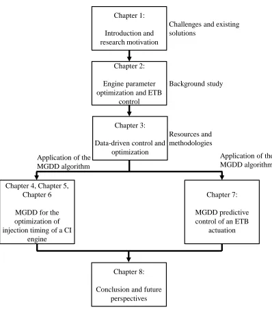
The outline of this dissertation is schematically presented in Figure 1-2. The motivation
of the research is first introduced in the present chapter. The preliminary knowledge
related to engine parameter optimization and ETB control is introduced in Chapter 2.
Three popular data-driven strategies are briefly summarized in Chapter 3. Chapters 2 and
3 provide the motivation and the technologies required for the derivation of the MGDD
algorithms. Three different examples on the optimization of injection timing for a CI
engine using different MGDD algorithms are presented in Chapters 4, 5, and 6. Chapter
7 demonstrates the actuation of an ETB valve using the MGDD predictive control
algorithm. Finally, concluding remarks and future perspectives are given in Chapter 8.
Ideally Accurate Model No Model Available Data-Driven Only Motivation: Model Availability Solution:
Control Strategy Model-Based
MGDD Approach Model with Uncertainties Main Contribution
8 Figure 1-2. Dissertation outline
Chapter 1:
Introduction and research motivation
Chapter 7:
MGDD predictive control of an ETB
actuation
Chapter 8:
Conclusion and future perspectives
Chapter 2:
Engine parameter optimization and ETB
control
Chapter 3:
Data-driven control and optimization
Chapter 4, Chapter 5, Chapter 6
MGDD for the optimization of injection timing of a CI
engine
Challenges and existing solutions
Background study
Resources and methodologies
Application of the MGDD algorithm
9
CHAPTER 2.
OPTIMIZATION OF INTERNAL COMBUSTION
ENGINE SYSTEMS AND ELECTRONIC THROTTLE CONTROL
Preliminary introductions of the optimization of IC engine parameters and the control of
the Electronic Throttle Body, ETB, are provided in this chapter. The challenges for the
engine parameter optimization and the ETB control are also addressed.
2.1Optimization of Internal Combustion Engine Systems
The calibration of an IC engine system is essentially a multi-objective optimization
problem [1][2]. The control parameters of an IC engine system are tuned to yield the
optimum system performance requirements. These performance requirements are often
trade-offs among fuel efficiency, emissions, and reliability [14][50]. Electronic actuators,
from simple versions like the ETB in the air-intake path to complex sub-systems with
integral intelligence, have been added to the IC engine systems to assist with the
achievement of the system performance requirements [51]. In traditional engine
calibration processes, extensive time and efforts have been invested to generate Look-Up
Tables, LUTs [52][53]. The LUTs are used to store the optimum parameters identified
under different engine calibrations [52][53]. Profound knowledge of engine operation
principles as well as advanced optimization methods is called in to complete the
sophisticated IC engine calibration process [54]. In this chapter, the Design of
Experiments, DOE, based optimization and the data-driven optimization are presented.
2.1.1 Design of Experiments Based Optimization
For an on-road vehicle, depending on different operating conditions, the onboard Engine
Control Unit, ECU, assigns the optimal parameters or reference trajectories from the
LUTs to different actuators based on different system performance requirements [54][55].
The DOE methods have been applied to determine the optimal control parameters on-line
or off-line [55-58]. The identified parameters are then stored inside the LUTs at different
engine operating conditions [55-58].
The creation of engine LUTs starts with the identification of the control variable limits
10
because of safety and engine performance concerns [7][9-12]. Usually, the minimal sets
of experiment points required from engine dynamometer tests can be generated using
different DOE methods. These methods include the full factorial design [62] and different
optimal design approaches [59][60-62].
The obtained test data, which often include the engine torque, emissions, and fuel
consumption measurement, are then applied for engine model identification and
validation [55][59-61]. The engine models can be built using regression or neural
network structures [59-61]. After a qualified model is obtained, the model-based
optimization techniques are used to determine the optimum control parameters. These
parameters can keep the engine model running under the desired performance
requirements [59-61]. Finally, the optimum parameters are recorded on different LUTs.
From the above descriptions, it is obvious that the system model plays an important role
in the DOE based optimization. In real practices, the DOE based optimizations are
realized with the considerations of different constraints and budget limits [60]. Despite
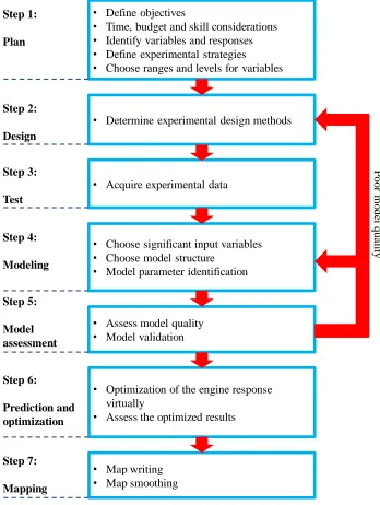
the differences, all DOE procedures do share a common workflow as summarized in
Figure 2-1 [50][60][61]. For the completeness of this work, a brief description of this
7-step workflow is given below:
Step 1.Plan: In this step, the objectives of the engine calibration are first defined. Time, budget, and available technical support are taken into consideration for choosing the
best experimental strategies. The viable operating boundaries and operational
constraints for the control variables are decided. The necessary system responses are
also identified to form a reasonable test plan.
Step 2.Design: Experimental setup and reasonable design methods, such as D-optimal design, are selected for the tests.
Step 3.Test: Experiments that are designed based on the preparations made in Step 1 and Step 2 are carried out on the engine dynamometer test bench. Test data are collected.
11
as different regression models, are chosen to build the relationships between the
system control inputs and the system outputs. The model parameters are derived
based on the experimental data collected in Step 3.
Figure 2-1. The model-based DOE steps
Step 5.Model assessment: The accuracy of the model is assessed. Experiment data other than the ones applied for model parameter identification are used for model validation.
Step 5:
Model assessment
• Define objectives
• Time, budget and skill considerations
• Identify variables and responses
• Define experimental strategies
• Choose ranges and levels for variables
• Determine experimental design methods
• Acquire experimental data
• Choose significant input variables
• Choose model structure
• Model parameter identification
• Assess model quality
• Model validation
• Optimization of the engine response virtually
• Assess the optimized results
• Map writing
• Map smoothing
12
If the model quality cannot meet the fidelity requirements, a redesign of the system
model is necessary, i.e. Step 1to Step 4 is repeated.
Step 6.Prediction and optimization: A target performance function is often defined for the model-based optimization using the identified engine model. The optimized
control parameters are assessed to validate their robustness under various system
operating conditions.
Step 7.Mapping: The obtained optimal parameters are mapped on the ECU LUTs. To close the gaps between the calibrated points and improve the transient response of the
IC engine, certain smoothing techniques are required to generate the final LUTs.
The LUTs derived through the DOE based optimization have been very effective for IC
engine operations. However, the efforts required to obtain the optimum parameters are
quite time-consuming [63-65]. Since the workflow requires model-based optimization,
the derivation of a reliable engine model is very important. The abundant choices of
available model structures and the addition of control actuators for the operation of IC
engines make the derivation of the IC engine models challenging [54][61][63-65].
2.1.2 Data-Driven Based Optimization
To reduce the effort in DOE based optimization, data-driven algorithms, such as the
Extremum Seeking Control, have been attempted as alternatives for the calibration of IC
engines. Data-driven algorithms are known for their quickness and directness in locating
the optimal parameters [63-68]. The operation of the Extremum Seeking Control, ESC,
relies solely on the relationship between the system input and output [63-65][70][71].
This makes the ESC a model-free optimization method. The tedious modeling work
required by the DOE based optimization is omitted. In a number of previous studies, the
calibrated parameters obtained by the ESC have shown similar or even better results
compared to the calibrated parameters obtained through DOE based optimization in terms
of different performance requirements [63][65]. Both the engine operation and the ESC
optimization can also proceed concurrently in real-time. This simultaneous operation
further reduces the strict design requirements proposed in the DOE based optimization,
13
[63-68]. A few examples of the optimization of IC engines using the ESC are presented
below:
Popovic et al. [63] have used ESC to optimize the valve timings and advanced spark
timing of an SI engine to make sure the engine operates at the best fuel efficiency.
Killingsworth et al. [64] optimized the combustion timing of a natural-gas engine using
the ESC by changing the temperature of the intake charge. The engine achieves the best
fuel efficiency at the selected operating point after the ESC optimization. In the study
carried out by Hellstrom et al. [65], the spark timing for an SI engine is optimized online
using the ESC to operate at its best thermal efficiency. Different ethanol/gasoline fuel
blends, as well as different engine speed/load conditions, are altered during the
optimization. Corti et al. [66] have applied ESC to optimize the air-fuel-ratio and the
spark timing for an SI engine. A higher Indicated Mean Effective Pressure, IMEP, under
constant fueling rate is achieved by the SI engine. Knocking intensity and the temperature
at the exhaust manifold are set as the constraints for this optimization task. Haskara et al.
[67] have optimized the spark timing of a gasoline engine using ESC when the engine
Exhaust Gas Recirculation, EGR, rate is increased without scarifying the combustion
stability. In Larsson et al.’ s work [68], the spark timing for reaching the highest possible
torque output from a gasoline engine is located using the ESC when the EGR ratio of the
engine is adjusted.
Although the ESC has shown advantages over the conventional DOE based optimization
in the aforementioned examples [63-68], the convergence speed of the ESC is usually
limited by the dynamic response of the system. This is caused by the requirement of
time-scale separation for averaging with singular perturbation [39][69]. Therefore, the
application of the ESC to systems with timely performance concerns would be unsuitable
[8]. How to improve the convergence speed of the ESC is, therefore, an interesting
research topic.
2.1.3 Model for a Compression Ignition Engine
In the automotive industry, various types of models for describing different processes
14
highly nonlinear, are usually validated via a large amount of experimental data to attain a
certain level of accuracy. Even if it is practically challenging to conduct a direct
model-based optimization/control design using some of these existing models, it is possible to
extract the output from the models to assist the ESC by providing a reasonable starting
point for the optimization. By using the feedforward information from the models, a
faster convergence of the ESC optimization can be expected.
Many available IC engine models are classified as Mean Value Models, MVMs [8].
MVMs are mostly control-oriented models represented by nonlinear differential
equations in the continuous time-domain [2][8]. The operation of an IC engine differs
from a continuously operating thermal engine mainly in two aspects [2][7][8]: (1) the
highly transient combustion process; (2) the varying thermodynamic boundary conditions
that affect the combustion process. Most existing MVMs focus on the modeling of the
thermodynamic boundary conditions. Therefore, the engine combustion is treated as a
static effect governed by the different boundary conditions [4][8]. The model parameters
of most MVMs are lumped parameters [4][8]. As a result, the output values from the
MVMs are considered as averaged effects over multiple IC engine cycles [4][8]. So far,
MVMs have been used to model the performance of the IC engines in a number of
applications. These include the load estimation of IC engines [72][73], the prediction of
air-path dynamics of a turbo-charged IC engine [74], and the approximation of NOx
emission of an IC engine [14].
Apart from MVMs, Discrete Event Models, DEMs, are also used to predict IC engine
performances under different operating conditions [8][75]. DEMs consider the system
operation as a sequence of discrete events and the approaching of a different event marks
the change of system states [8][75]. The system is assumed to remain unchanged during
two consecutive events [8]. As a result, simulations of DEMs are simply calculated at
each event while the processes between the events are neglected [8]. This is the main
difference compared to MVMs as continuous time has been broken into small-time
sections, hence the states of the DEMs are updated in accordance with the activities that
15
For IC engine models, the DEMs are defined in the crank-angle domain, i.e. all the
control input and the system states become functions of the engine crank-angle 𝜑. This is extremely convenient for modeling the performance of IC engines because the
reciprocating nature of the IC engine operation makes its analysis convenient as a
discrete event process [8].
In this work, a DEM engine model has been selected to support the development of
different MGDD algorithms for the optimization of fuel injection timing in a CI engine
constrained by different performance requirements. The model is developed based on the
first law of thermodynamics applied to the trapped gases in the combustion chamber [28].
Empirically developed sub-models for the heat transfer and combustion processes are
incorporated in this model. The details for the DEM model can be found in the work
titled ‘Clean combustion control in a compression ignition engine’ [28]. For the
completeness of this work, the model is briefly presented in this subsection.
In the model, the crank-angle 𝜑 has a resolution of 1𝑜crank angle. 𝑝
𝑛(𝜑) represents the in-cylinder pressure at 𝜑 within the nth engine cycle. 𝜃𝑛 is the control input for the model. In the model, 𝜃𝑛 is the crank angle for the Start of Combustion, SOC, at the 𝑛𝑡ℎ engine cycle. 𝒖𝒏 is the global input for the CI engine model. In this work, 𝒖𝒏 comprises of the engine speed, 𝜔𝑅𝑃𝑀, and the cyclic delivered fuel mass, 𝑚𝑓𝑢𝑒𝑙. 𝑉(𝜑) is the instantaneous cylinder volume at crank angle 𝜑.
Cylinder Volume
𝑉(𝜑) is expressed as
𝑉(𝜑) = 𝑉𝑐 +𝑉𝑠 2 [
1 + 𝑙
𝑎− 𝑐𝑜𝑠(𝜑) − (( 𝑙 𝑎)
2
− 𝑠𝑖𝑛2(𝜑)) 1 2
]
(2-1)
16
In-Cylinder Bulk Gas Temperature
It is assumed that between 𝜑 and 𝜑 + 1, the in-cylinder process is a quasi-steady state process. When all gas exchange valves are closed, 𝑇𝑛 is the in-cylinder bulk gas temperature, given by:
𝑇𝑛(𝑝𝑛, 𝜑) = [
𝑝𝑛(𝜑) ∙ 𝑉(𝜑) 𝑅̅ ∙ 𝑁𝑖𝑚
] (2-2)
where, 𝑅̅ is the universal gas constant and 𝑁𝑖𝑚 is the total moles of in-cylinder gas when all the gas-exchange valves are closed.
The total moles of the trapped gas are assumed to stay constant during the in-cylinder
process. The 𝑁𝑖𝑚 is defined by:
𝑁𝑖𝑚 = 𝜂𝑉[𝑝𝑖𝑛∙ 𝑉𝑠
𝑅̅ ∙ 𝑇𝑖𝑛] (2-3)
where 𝑝𝑖𝑛 is the intake manifold pressure, 𝑇𝑖𝑛 is the intake temperature, and 𝜂𝑉 is the volumetric efficiency.
The Rate of Wall Heat Transfer
For the engine test setup in the author’s lab, the rate of wall heat transfer 𝛿𝑄ℎ𝑡 is modeled using Woschni’s empirical correlation with the following settings [7]:
𝛿𝑄ℎ𝑡(𝜑, 𝒖𝒏, 𝜃𝑛) = ℎ𝑤(𝑝𝑛, 𝜑) ∙ 𝐴𝑠 ∙ [𝑇𝑛(𝑝𝑛, 𝜑) − 𝑇𝑤𝑎𝑙𝑙] (2-4)
where
ℎ𝑤(𝑝𝑛, 𝜑) = 𝐶1∙ 𝐵−0.2∙ 𝑝𝑛(𝜑)0.8∙ 𝑇
𝑛(𝑝𝑛, 𝜑)−0.55∙ 𝑤(𝑝𝑛, 𝜑)0.8 (2-5)
and
𝑤(𝑝𝑛, 𝜑) = 𝐶2∙ 𝑆̅̅̅ +𝑝 𝑉𝑠∙ 𝑇𝑟𝑒𝑓
17
𝐴𝑠 is the surface area of the combustion chamber, 𝐵 is the cylinder bore, 𝑆̅̅̅𝑝 is the mean piston speed, and 𝑝𝑚𝑜𝑡 is the cylinder pressure obtained during engine motoring, i.e. engine rotation with the help of a motor but without the presence of combustion. 𝑇𝑟𝑒𝑓, 𝑝𝑟𝑒𝑓, and 𝑉𝑟𝑒𝑓 are the reference states used for calculating the heat transfer following the combustion event. The wall heat transfer coefficients, 𝐶1 and 𝐶2 , as well as the combustion chamber wall temperature, 𝑇𝑤𝑎𝑙𝑙, are calibrated based on the engine geometry. Once calibrated, the coefficients and the wall temperature are kept constant
throughout the simulation study. The values of the selected model parameters are later
presented in Table 4-2.
The Rate of Heat Release
A triangular function is used to approximate the rate of heat release, 𝛿𝑄ℎ𝑟:
𝛿𝑄ℎ𝑟(𝜑, 𝒖𝒏, 𝜃𝑛) = {
0
(2 ∙ 𝑄ℎ𝑟𝑀𝐴𝑋)(𝜑 − 𝜃𝑛)
(−2 ∙ 𝑄ℎ𝑟𝑀𝐴𝑋)(𝜑 − 𝜑𝐶𝐴50) + 𝑑𝑄ℎ𝑟𝑀𝐴𝑋 0 𝑖 𝑖𝑖 𝑖𝑖𝑖 𝑖𝑣 (2-7) where, { 𝑖: 𝑖𝑖: 𝑖𝑖𝑖: 𝑖𝑣:
𝜑 < 𝜃𝑛 𝜃𝑛 < 𝜑 < 𝜑𝐶𝐴50 𝜑𝐶𝐴50< 𝜑 < [𝜃𝑛 + 𝜑𝐶𝐷]
𝜑 > [𝜃𝑛 + 𝜑𝐶𝐷]
(2-8)
𝑄ℎ𝑟𝑀𝐴𝑋 =𝑚𝑓𝑢𝑒𝑙∙ 𝐿𝐻𝑉
𝜑𝐶𝐷 (2-9)
𝜑𝐶𝐴50 is the crank angle of 50% accumulated heat release. 𝜑𝐶𝐴50 is approximated by:
𝜑𝐶𝐴50 = 𝜃𝑛 +𝜑𝐶𝐷
2 (2-10)
18
Engine Work Output
𝛿𝑊𝑛 is the work output from the CI engine. 𝛿𝑊𝑛 is derived by:
𝛿𝑊(𝑝𝑛, 𝜑) = 𝑝𝑛(𝜑) ∙ [𝑉(𝜑) − 𝑉(𝜑 − 1)] (2-11)
In-Cylinder Pressure
It is assumed that the trapped gas is ideal gas, and between 𝜑 and 𝜑 + 1, the in-cylinder process is a quasi-steady isochoric process. Thus, the change of the in-cylinder bulk gas
temperature can be expressed as:
𝑇𝑛(𝜑 + 1) =
𝑇𝑛(𝜑) + 𝛼𝑛∙ [𝛿𝑄𝑛(𝜑, 𝒖𝒏, 𝜃𝑛) − 𝛿𝑊𝑛(𝜑, 𝑝𝑛)]
(2-12)
where α𝑛 is related to the ratio of specific heats, 𝛾𝑛 , of the in-cylinder gas mixture and is given by:
𝛼𝑛 = [𝛾𝑛− 1 𝑅̅ ∙ 𝑁𝑖𝑚
]
(2-13)
The ratio of specific heats 𝛾𝑛 usually changes with the temperature 𝑇𝑛. To simplify the model computation, in this work, 𝛾𝑛 is approximated as a constant value:
𝛾𝑛 = 𝛾𝜑𝐼𝑉𝐶 (2-14)
where 𝛾𝜑𝐼𝑉𝐶 is the ratio of specific heats of the gas mixture obtained at the crank angle of Intake Valve Closing, IVC. Based on the previous investigation, for the engine test setup
in the author’s lab, 𝛾𝜑𝐼𝑉𝐶 = 1.37 [76].
𝛿𝑄𝑛(𝜑, 𝒖𝒏, 𝜃𝑛) is defined as the difference between 𝛿𝑄ℎ𝑟(𝜑, 𝒖𝒏, 𝜃𝑛) and 𝛿𝑄ℎ𝑡(𝜑, 𝒖𝒏, 𝜃𝑛), i.e. 𝛿𝑄𝑛(𝜑, 𝒖𝒏, 𝜃𝑛) = 𝛿𝑄ℎ𝑟(𝜑, 𝒖𝒏, 𝜃𝑛) − 𝛿𝑄ℎ𝑡(𝜑, 𝒖𝒏, 𝜃𝑛).
Therefore, the in-cylinder pressure can be derived as:
𝑝𝑛(𝜑 + 1) = [𝑇𝑛(𝜑 + 1) ∙ 𝑅̅ ∙ 𝑁𝑖𝑚
19
In this work, the DEM model, described by equations from (2-1) to (2-15), is integrated
into different MGDD optimization applications presented in CHAPTER 4 - 6.
2.2Electronic Throttle Control
The improvement of control strategies for IC engine systems has become a driving factor
in automotive innovation and development [4][8]. To meet different performance
requirements, all corresponding electrical actuators on an IC engine need to work
collectively and accurately track the optimum parameters determined by the calibrated
LUTs [4][50][60][61].
The ETB system is a suitable example, in the intake air-path of an SI engine, the ETB is
usually installed at the upstream of the intake manifold. The actuation of the ETB
opening can affect the quantity of air-flow into the engine cylinder [5][7][77-79]. The
quality of the in-cylinder air-fuel mixture is controlled by the ETB actuation. As a result,
the engine torque is regulated [80-82].
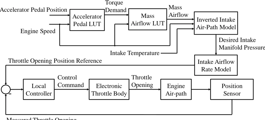
As shown in Figure 2-2 [80-82], when the accelerator pedal is pressed, a change of the
pedal position is detected. The two inputs, i.e. the pedal position and the measured engine
speed, are sent to the Accelerator Pedal LUT, where the value for the corresponding
engine torque is fitted [80][81]. Together with the measured engine speed, the engine
torque is applied as an input for the Mass Airflow LUT to find the desired mass air flow
in the intake manifold for the SI engine [80][82]. Through the calculation of a series of
mathematical models, the ETB opening can be determined [80-82]. A local controller is
presented to make sure the ETB can track the opening position reference derived from the
20
Figure 2-2. Torque-based throttle opening estimation
Fast and accurate ETB actuation can be achieved if the local controller is properly
designed. As a result, the SI engine can respond to different torque demands immediately
and fulfill the performance requirements [7][8][83].
A schematic of the ETB system is presented in Figure 2-3. The opening of the ETB
butterfly valve is governed by a Direct Current, DC, motor through a set of gears.
Limp-home spring is also mounted in line with the axle of the butterfly valve. The spring
exercises a torque on the throttle plate to pull it back to the default limp-home position.
The limp-home position is a fail-safe position of the ETB when motor actuation is not
applied. By design, if the ETB system is out of order, the ETB is mechanically kept open
with a small angle that allows the driver to ‘limp’ the vehicle to a safe place [77-79]. A
pair of redundant position sensors is also embedded in the ETB system. The sensors
provide voltage signals that are proportional to the opening of the ETB valve.
Accelerator
Pedal LUT Inverted Intake
Air-Path Model Accelerator Pedal Position
Engine Speed Mass Airflow LUT Torque Demand Mass Airflow Intake Temperature Throttle Opening Position Reference
Local Controller Electronic Throttle Body Position Sensor
21 Figure 2-3. Schematic of an ETB
2.2.1 Existing Challenges
The control of the ETB opening requires the consideration of the presence of multiple
nonlinearities. These nonlinear characteristics are the limp-home spring nonlinearity, the
stick-slip friction, and the gear backlash [77-79][84]. The nonlinearities are more
noticeable when the ETB is near the fully closed position [85].
Figure 2-4. ETB valve opening affected by the flow of air
Even though the ETB is used to regulate air flow in an SI engine [86], the presence of air
movement can disturb the ETB opening. As shown in Figure 2-4, the ETB opening would
first increase because of the control input change that is highlighted by the red arrows in
the figure. As the test proceeds, the value of control input remains constant and the air
flow alone changes the opening of ETB position as pointed out by the black arrow in the
Gear Box
DC Motor
Throttle Plate
Opening Angle
Position sensors Limp-home
spring
Gear Box
Throttle Plate
Limp-Home
Spring
Position
Sensor
DC Motor
22
figure. To improve the system robustness against air flow disturbances, closed-loop
control is required.
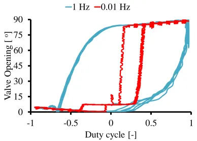
The ETB system also demonstrates rate–dependent characteristics as shown in Figure 2-5.
From the figure, it is obvious that the ETB would respond differently when the
frequencies of control inputs are changed. Therefore, the closed-loop controller designed
for ETB actuation needs to be adaptive, so the system can perform satisfactorily under
dynamic or steady-state conditions alike.
Different solutions have been proposed to achieve the prompt and accurate control of the
ETB system.
Figure 2-5. Rate-dependent characteristics of an ETB system
2.2.2 Existing Solutions
Previously, different closed-loop control strategies have been attempted for ETB control
[77][88-90]. In general, the methods can be characterized into two categories: Using
either the data-driven control strategies or the model-based control strategies.
The Proportional-Integral-Derivative, PID, control is the most popular strategy exercised
for the majority of automotive control applications [80]. The presence of a system model
is not necessary for the design of PID gains, thus under certain scenarios, the PID control
can be considered as a type of data-driven control [15]. Multiple PID gains are usually
required for the PID control of ETB [87]. A few examples on the PID controlled ETB are
briefly summarized as follows:
0 15 30 45 60 75 90
-1 -0.5 0 0.5 1
V al v e O pe ni ng [ o]