1
Comparative study of erosion-corrosion performance on a range of stainless steels
L Giourntasa, T Hodgkiessb, A M Gallowaya
a
Department of Mechanical and Aerospace Engineering, University of Strathclyde, Glasgow
b
Porthan Limited, Lochgilphead, Scotland
1.
Introduction
Erosion-corrosion is a material deterioration phenomenon that occurs in hydraulic machinery that handles aggressive slurries. Many industries attempt to mitigate this challenging feature by modifying the design of components and/or by selecting more erosion-corrosion resistant materials. The latter strategy often involves the selection of corrosion resistant alloys (CRAs), which exhibit good performance in many environments instead of using coating techniques to shield vulnerable materials such as carbon steels even if this increases the initial cost.
An important attribute of the group of materials known as stainless steels is their capacity to resist high flow rates of many aqueous fluids. This contributes to the selection of various types of stainless steel in many engineering applications. Numerous studies have demonstrated that stainless steels display good erosion-corrosion performance in solid-free liquid impingement conditions [1,2]. This good behaviour is due to the ability of its chromium-rich, oxide passive film to resist breakdown even in rapidly flowing liquids and relatively high temperatures (up to 60oC)[3].
It is well known [4] that the durability of stainless steels decreases when suspended solids are present in the flowing liquid. On account of the diversity in composition, metallurgical structure and mechanical properties in stainless steels, it is of interest to compare the erosion-corrosion behaviour of a range of such materials in these more aggressive conditions.
Many past investigations, however, have focused on individual grades of stainless steel, such as the standard austenitic UNS S31600/31603 [5–9] and similar austenitic stainless steel UNS S30400 [10– 12]. When more than one stainless type has been studied they have usually comprised comparing two grades. Examples of such work are studies of UNS S31600 versus superaustenitic stainless steel [13,14], comparison of austenitic UNS S30400 with martensitic UNS S42000 [15], martensitic UNS S41000 against UNS S32760 [16] and duplex/superduplex versus UNS 31600 [17,18]. Some of these researchers have also demonstrated the superior erosion-corrosion resistance of stainless steels over carbon steels [16,17,19,20].
Another important feature, of many studies of the erosion corrosion behaviour of stainless steels (and other materials), has been the application of cathodic protection (CP) for the assessment of the potential benefits of the material durability and also in unravelling of erosion corrosion mechanisms [13,14,17,21].
2
included free erosion corrosion conditions and also experiments involving the application of cathodic protection.
2.
Materials under study and experimental methodology
The steels, that were considered in this study, were an austenitic stainless steel (UNS S31600), two martensitic stainless steels (UNS S42000 and precipitation hardened martensitic UNS S17400), a superduplex stainless steel (UNS S32760) and a medium carbon steel (UNS G10400). The nomimal compositions of all the studied steels are presented on Table 1.
Material C% W% Cr% Ni% Mo% S% Mn
% Cu% Si% N%
Nb+ Ta% UNS
S31600 0.08 17.5 12 2.5 <0.03 <2 <0.75 <0.1 UNS
S32760
0.03
Max 0.75 25 7 3.5 <0.01 1
Max 0.75 0.25
UNS
S42000 <0.15 13 <0.03 <1 <1
UNS
S17400 <0.07 16.5 4 <0.03 <1 4 1 0.3
UNS
[image:2.595.80.516.197.412.2]G10400 0.40 0.05 0.75
Table 1 Nominal composition of the steels.
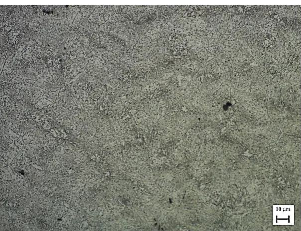
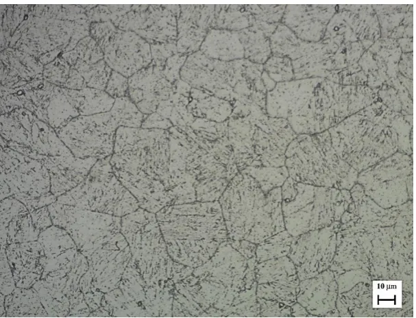
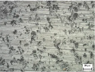
Micro-structural analysis, with an Olympus GX51 microscope, was completed prior to testing to identify the different structures of the steels. Figures 1-5 display the structures of the steels after polishing to 3μm diamond and either etching in Nital (for the carbon steel) or electrolytic etching with 10% oxylic acid for the stainless steels.
[image:2.595.145.450.490.720.2]3
Figure 2. Ferrite matrix and austenite grains in UNS S32760
[image:3.595.146.449.327.559.2]4
[image:4.595.144.450.342.576.2]Figure 4. Martensitic structure with the presence of carbide precipitates within the matrix and also on the grain boundaries in UNS S17400
Figure 5. Typical ferrite/pearlite structure of medium carbon steel in UNS G10400
Also, a macro-hardness tester, Vickers MAT31 was used to obtain the hardness values with 5kgf load, shown in Table 2, for each grade of steel.
Material UNS S31600 UNS S32760 UNS S42000 UNS S17400 UNS G10400
Hardness (HV) 200 257 280 358 240
5
The erosion-corrosion performance was assessed as follows:
1) Mass loss tests were carried out under solid/liquid impingement in free erosion-corrosion conditions as well as with the application of cathodic protection which isolated the mechanical damage.
2) Potentiodynamic anodic polarisation experiments were conducted in solid/liquid impingement and in static conditions to evaluate the pure electrochemical processes. 3) Post-experimental analysis was facilitated initially with the Olympus GX51 microscope to
review the surface in more detail. Alicona Infinite Focus equipment was used to determine the wear scar depths. Also, a Mitutoyo SurfTest SV 2000 machine was employed for the surface roughness evaluation in different regions of the post-test surface.
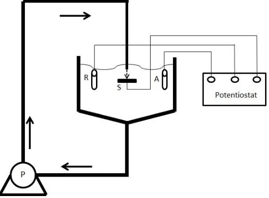
The erosion-corrosion experiments were carried out using a circulating closed loop rig (Figure 6). The duration of the tests was 30 minutes. The nozzle diameter was 3 mm and the slurry, which consisted of 3.5% NaCl and sand particles, impinged at 24m/s velocity perpendicular to the specimen surface. The silica sand particles used in this study possesses hardness of 1160HV with spherical shape, as shown in Figure 7. The sand concentration, which was measured directly under the nozzle, was 200±20mg/l. Table 3 represents the sand particle size distribution. The testing temperature range was 30oC-35oC. The specimens, of 3.8cm diameter, were ground on 220, 500, 800, 1200 SiC grit papers, and achieved 0.07μm average roughness values (Ra). The specimens had an offset distance of 5mm from the nozzle. The mass losses in each case were measured by using a mass balance of accuracy 0.1mg. For the medium carbon steel, which displayed significant corrosive attack, specimens were immersed briefly in an inhibited acid solution (Clark solution-consisting of 1000 mL of hydrochloric acid, 20 g of antimony trioxide (Sb2O3) and 50 g of stannous chloride (SnCl2)) prior to the
[image:5.595.157.433.458.661.2]determination of the mass loss. For the experiments that employed CP, the electrode potential was kept at -0.85mV (Ag/AgCl reference electrode) at which the anodic current densities were estimated to be less than 0.01μA/cm2.
6
Figure 7. Microscopic view of the spherical shape silica sand prior testing. Size (μm) <250 251-355 356-420 421-500 501-600 601-710 >711
[image:6.595.159.438.71.279.2]Mass (%) 0.05 3.2 5.3 18.3 70 3.1 0.05
Table 3. Size distribution of the silica sand.
7
3.
Results
3.1
Mass loss measurements
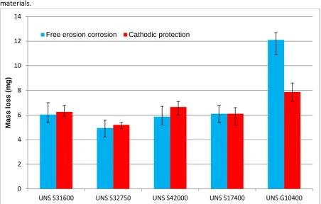
[image:7.595.72.525.224.512.2]Figure 8 compares the mass loss measurements in free erosion corrosion experiments and cathodic protection impingement tests. The error bands represent the scatter between at least three replicates. The cathodic protection tests were carried out after the completion of the free erosion-corrosion experiments and, the scatter in the recorded mass losses indicated that less replication was necessary. The performances of all the stainless steels were superior to that of the medium carbon steel. Three of the stainless steels exhibited quite similar behaviour under these erosion-corrosion conditions but the superduplex stainless steel had the lowest mass loss of all the tested materials.
Figure 8. Mass loss of the steels with and without cathodic protection.
The application of cathodic protection resulted in a substantial reduction in the mass loss on the medium carbon steel (UNS G10400). This was not the case for the stainless steels, for which the mass losses were similar. This aspect, associated with the behaviour on the cathodic protection, is considered in more detail in the discussion section.
3.2
Anodic polarisations
Anodic polarisation scans were conducted on all the tested materials in static corrosion conditions and also in solid/liquid impingement. The results are presented in Figures 9 and 10 in which the starting electrode potentials have been normalized to zero in order to facilitate comparisons between the various alloys. As Figure 9 shows the carbon steel displayed rapidly rising current (typical of active corrosion). In contrast, the stainless steels exhibited much lower currents; this is typical of corrosion resistant materials.
0 2 4 6 8 10 12 14
UNS S31600 UNS S32750 UNS S42000 UNS S17400 UNS G10400
M
as
s l
o
ss
(
mg
)
8
Figure 9. Anodic polarisation sweeps under static corrosion conditions.
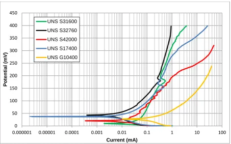
Figure 10 demonstrates the anodic polarisation sweeps of all the materials during solid/liquid impingement. The behaviour of all the materials altered significantly under these conditions. The medium carbon steel sustained its active behaviour but it was corroding at a higher rate. The stainless steels, displayed considerably higher currents than in quiescent water because of the passivity breakdown due to the presence of 200ppm silica sand particles. The rapidly oscillating currents are indicative of periodic de-passivation and re-passivation events.
0 50 100 150 200 250 300 350 400 450
0.000001 0.00001 0.0001 0.001 0.01 0.1 1 10 100
P
ot
e
nt
ia
l
(mV
)
Current (mA)
9
Figure 10. Anodic polarisation scans under solid/liquid impingement.
Tafel extrapolation was used to generate the corrosion currents for all tested metals under solid/liquid impingement. The extrapolation of the stainless steels’ scans involved plotting a straight line running approximately through the maximum of the oscillating currents. The resulting corrosion currents in milliamps are presented in Table 4.
Material Impingement Icorr (mA)
UNS S31600 0.2
UNS S32760 0.1
UNS S42000 0.5
UNS S17400 0.2
[image:9.595.133.465.483.572.2]UNS G10400 3.3
Table 4. Corrosion currents in free erosion-corrosion conditions.
3.3
Microscopic observations/Roughness measurements
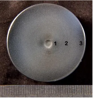
Figure 11 shows the typical post-test surface of all materials. The deep wear scar under the impinging jet is evident together with a number of other surface deterioration regions outside the wear scar. Figures 12-14, representative of all the materials, show the microscopical structure of UNS S31600 of the three zones marked 1, 2, and 3 on Figure 11. The turbulent area was present immediately adjacent to the wear scar. Figure 12 shows that this turbulent zone (marked 1 in Figure 11) results mostly in sliding abrasion as abrasion marks are displayed following the flow direction. Figure 13 demonstrates the region next to the turbulent zone (marked 2 in Figure 11), referred to herein as the severe outer area. The severe outer area exhibited less turbulence which resulted in less abrasion. The outermost region of the specimen (marked 3 in Figure 11) displayed the least surface degradation as is clear from the appearance of the surface preparation grinding scratches, as shown on Figure 14.
0 50 100 150 200 250 300 350 400
0.001 0.01 0.1 1 10 100
10
Figure 11. Surface of UNS 31600 after solid/liquid impingement with the three different regions beyond the wear scar.
[image:10.595.129.465.454.711.2]11
Figure 13. Severe outer area (2) of the UNS S31600 after solid/liquid impingement.
Figure 14. Outermost area (3) of the UNS S31600 after solid/liquid impingement.
[image:11.595.130.466.375.628.2]12
Figure 15. Outermost area (3) of the UNS G1040 after solid/liquid impingement
The outcomes from the microscopic analysis led to the idea of measuring the roughness of these areas. Table 5 illustrates the average surface roughness values (Ra) of all the materials’ post-test surfaces and quantifies the trends of reducing surface roughness from the turbulent zone to the outermost region.
Average roughness Ra (μm)
Area of interest UNS S 31600 UNS S 32760 UNS S 42000 UNS S 17400 UNS G10400
Turbulent zone 0.445 0.4095 0.419 0.391 0.452
Severe outer
area 0.2875 0.2635 0.3195 0.277 0.305
Outermost area 0.134 0.099 0.125 0.126 0.179
Table 5. Average roughness values of the three different degradation regions in all steels.
3.4
Surface Profile scans
[image:12.595.75.529.609.721.2]In order to compare the behaviour of the different materials in the zone directly under the impinging jet (wear scar), surface profile scans were completed on all specimens. Figure 16 illustrates an example of a U-shaped wear scar profile on the superduplex stainless steel, which is again typical of all the materials including the medium carbon steel.
13
Figure 17 shows the wear scar depths of all the studied materials with and without cathodic protection. It is clear that the superduplex stainless steel exhibits the lowest wear scar depth which implies that it had superior performance. The other comparative materials have similar wear scar depths in both environments. A very interesting feature is that the application of CP has not generally resulted in significant reduction in wear scar depth, which demonstrates that the damage within the direct impinged zone is erosion dominated.
Figure 17. Wear scar depths of the studied materials in erosion corrosion conditions with and without cathodic protection.
3.5
Sand breakage
Past erosion studies showed that the hardness ratio of the target and the particles played a significant role on the erosion mechanisms occurring on the surface [22,23]. In addition to that, the sand breakage is likely to happen when the hardness ratio (Ht/Hp) is more than 1. In this study, the hardness of the silica sand used was at least 3 times higher than the hardness magnitude of the steels, in other words Ht/Hp << 1. Thus, no sand breakage was expected to happen. Figure 18 demonstrates this feature, as compared to Figure 7; the sand particles have sustained their size and their spherical shape even after a 30 minute erosion-corrosion test.
0 20 40 60 80 100 120 140 160
UNS S31600 UNS S32760 UNS S42000 UNS S17400 UNS G10400
W
ea
r
sc
ar
d
ept
h
(
μ
m)
[image:13.595.76.522.163.484.2]14
Figure 18. Silica sand particles after 30 minutes solid/liquid impingement
4.
Discussion
4.1
Erosion-corrosion Mechanisms
The erosion-corrosion phenomenon consists of pure mechanical degradation (E), pure electrochemical deterioration (C) and also the interaction of both which is often called synergy (S). Equation 1 demonstrates the relationship of the factors above.
TML = E + C + S Equation 1
The total mass loss is obtained through free erosion corrosion tests. Cathodic protection is applied to isolate the mechanical damage by mitigating any pure corrosion reactions.
From Figure 8, it is evident that the mass loss of the carbon steel was substantially reduced by the application of cathodic protection. However, this was not the case of any of the stainless steels. It is evident that, in the erosion-corrosion conditions used in this study, the erosion-corrosion mechanisms of stainless steels are erosion dominated. This feature may be associated with the silica sand characteristics, such as type and size.
Of course, the situation of erosion dominated damage implies negligible synergy and pure corrosion. The magnitude of pure corrosion is discussed 4.2, and in relation to the synergy factor, it is interesting Burstein and Sasaki observed a systematic decrease in the proportion of synergy during erosion corrosion of UNS S30400 with increasing impact angle [12]. Thus, the observation of the present work of erosion dominated attack (the ineffectiveness of cathodic protection) may not prevail under impingement at angles less than 90o.
Another possibility is that the mass losses exhibited during application of cathodic protection were enhanced by local hydrogen embrittlement mechanisms. To test for this possibility two cathodic protection replicates were undertaken on the most susceptible stainless steel (UNS S42000) at a more negative cathodic potential (-1V) to obtain any possible differences in its erosion behaviour. Table 6 shows that the mass losses and the wear scar depths were similar to those obtained with cathodic potential at -850mV. This indicates the absence of hydrogen embrittlement mechanisms in the erosion corrosion process.
UNS S42000 CP (-850mV) CP (-1V) Replicate 1 CP (-1V) Replicate 2
Mass loss (mg) 6.7 (Average) 7.0 7.0
15
Table 6. Comparison of the mass loss and wear scar depth of the UNS S42000 at different cathodic potentials.
4.2
Corrosion
Anodic polarisation scans in static conditions show that stainless steels exhibit very low corrosion rates in comparison to the medium carbon steel that was corroding actively at relatively high rates. This is an expected observation, since it is well known that high chromium content (>12% Cr) causes the formation of a passive film that protects the metal against corrosion. With addition of solid particles, the environment becomes more severe and the stainless steels fail to maintain their protective film which results in enhanced corrosion rates but which are, nevertheless, much lower than those of the medium carbon steel. The current fluctuations, as the potential sweeps to more positive values, demonstrate the capacity of the stainless steel to periodically reform its film in between de-passivation events caused by the erosive particles. It is apparent that the improved corrosion resistance of superduplex stainless steel in static conditions is also a feature in erosion corrosion environments. A correspondence between alloy chromium content and corrosion rates in erosion corrosion conditions is evident in Table 4.
Conversion of the corrosion current values in Table 4 to mass losses, via Faraday’s Law calculation, yields, e.g. UNS S31600, a value of mass loss (C) of 0.1mg which represents only 1.6% of the total mass loss. This feature is in agreement with the data in Figure 8 in demonstrating that the erosion-corrosion deterioration process was erosion dominated. On the other hand, Faraday’s Law calculation for the carbon steel produces a corrosion mass loss 1.7mg and, using Equation 1, a mass loss by synergy of 2.5mg. These figures show that the corrosion and synergy proportion are C=14% and S=20%, respectively.
4.3
Erosion
Another noteworthy outcome of this study is the topography of the surfaces after impingement. The silica sand developed U-shape wear scars which are usually formed on brittle materials. Others have shown that the wear scar of UNS S31600 after solid/liquid impingement with angular sand is W-shaped [8]. It is obvious that such behaviour has not occurred at this study. It is apparent that wear scar morphology is a complex function of factors such as sand characteristics (type, size, shape, and concentration), aqueous solution chemistry and jet velocity. These features might result in the absence of the stagnation point on the ductile metal surfaces.
4.4
Sliding Abrasion
The surface roughness measurements (Table 5) established that the region immediately outside the wear scar (Figure 11) is relatively turbulent in agreement with general opinion of the hydrodynamics of a submerged jet and supported by CFD models [8]. The large diameter of the specimens helped to assess more extensively the wear mechanisms occurring outside the wear scar and exhibited three discrete areas of progressively diminishing roughness starting from the most turbulent region. A particularly interesting feature is that these outer deterioration zones displayed similar roughness in all metals even if they were different in terms of hardness, ductility and strength. It is thus apparent that the mechanical properties of the steels studied herein did not reflect in any significantly different resistances to 0o angle abrasion.
16
performance against corrosion as there were copious corrosion products outside the wear scar. It is clear that the corrosion occurred on the metal surface was mostly general corrosion as there was no evidence of localised corrosion attack.
4.5
Stainless steels comparisons
It is interesting that three of the stainless steels (UNS S31600, UNS S42000, and UNS S17400) exhibited very similar mass loss, wear scar depths and surface roughness despite their quite different metallurgical structures and hardness. Thus, it would appear that the very severe erosion-dominated conditions prevailing in this study (e.g. 0.1mm wear scar depth in 30 minutes) has a tendency to override any influences of the metallurgical conditions and mechanical properties in the austenitic, martensitic and precipitation strengthened stainless steels. On the other hand, the superduplex stainless steel had a superior performance compared to the other stainless steels. This discrimination of the stainless steels is indirectly supported by previous investigations of solid/liquid impingement in saline water at perpendicular incidence as summarized below. One study indicated that UNS S32760 is superior to martensitic stainless steel UNS S41000 [16]. Other work showed that the erosion-corrosion resistances of the superduplex stainless steel (UNS S32760), Inconel 625 (UNS N00625) and Stellite 6 (UNS AMS53877) were similar [4]. Another investigation demonstrated a similar Stellite material (Stellite X40) was found to be superior to UNS S17400 [24]. There are general indications from the literature that different grades of duplex stainless steel, standard duplex (UNS S22050) [17], superduplex UNS S32760 [18] and lean (lower Ni and Mo) duplex stainless steels UNS S32101 [25] possess superior erosion-corrosion resistance than austenitic stainless steels such as UNS S31600 and UNS S30400.
In considering, in more detail, the trends displayed in the current study, the first point is that the superior corrosion resistance of the superduplex steel is clearly not a factor in the erosion-dominated situation. It is also apparent that the relative hardness of the tested materials is not of a significant factor in erosion-corrosion performance. This feature demonstrates the benefits of investigating, as in the current study, a range of stainless steel metallurgical types because, for instance, comparison of just superduplex stainless steel with austenitic stainless steel might indicate that the improved erosion-corrosion resistance of the superduplex steel is associated with tis higher alloy content and hardness. A more appropriate interpretation of the findings in this study might be the tendency for phase transformation from austenite to martensite under the work hardening effect produced by impacting sand particles. This might provide an explanation for the similar observed erosion-corrosion behaviour of austenitic and martensitic alloys and also the difference between the superduplex steel and austenitic alloy as has been argued by Aribo et all [25], in connection with the comparative behaviour of lean duplex stainless steels and austenitic UNS S30400.
5.
Conclusions
17
2. Superduplex stainless steel performed superiorly in corrosion and erosion-corrosion conditions. This might mean that it would be a favoured choice in engineering cases where marginal solid/liquid conditions (low velocity and low sand burdens) are involved.
3. The austenitic and the two martensitic stainless steels exhibited similar overall erosion-corrosion behaviour despite the diversity in their mechanical properties and their chemical compositions.
4. There are significant benefits that accrue from the application of cathodic protection to carbon steels in erosion corrosion conditions. This is clearly due to the suppression of corrosion and synergy on these materials on the regions outside the direct impinged zone. 5. In the conditions used in this study, it was apparent that the cathodic protection was
ineffective for stainless steels, indicating erosion dominance, although this factor may be restricted to the 90o angle involved.
6. The findings from this study of a range of stainless steel metallurgical types, provides more evidence that simple correlation of erosion-corrosion behaviour with the material hardness is questionable. The relative performances of the stainless steels in this study might be linked to the transformation from austenite to martensite under solid particle impingement. Acknowledgement
The authors would like to acknowledge the support for this study, which was provided by the Weir Group PLC via its establishment of the Weir Advanced Research Centre (WARC) at the University of Strathclyde.
References
[1] K.S.E. Al-Malahy, T. Hodgkiess, Comparative studies of the seawater corrosion behaviour of a range of materials, Desalination. 158 (2003) 35–42.
[2] K. Sasaki, G.T. Burstein, Erosion–corrosion of stainless steel under impingement by a fluid jet, Corros. Sci. 49 (2007) 92–102.
[3] T. Neville, A, Hodgkiess, An assessment of the corrosion behaviour of high-grade alloys in seawater at elevated temperature and under a high velocity impinging flow., Corros. Sci. 38 (1996) 927–956.
[4] A. Neville, T. Hodgkiess, Characterisation of high-grade alloy behaviour in severe erosion – corrosion conditions, Wear. 233-235 (1999) 596–607.
[5] Y.G. Zheng, Z.M. Yao, W. Ke, Erosion – corrosion resistant alloy development for aggressive slurry flows, Mater. Lett. 46 (2000) 362–368.
[6] M. Divakar, V.K. Agarwal, S.N. Singh, Effect of the material surface hardness on the erosion of AISI316, Wear. 259 (2005) 110–117.
[7] R.J.K. Wood, J.C. Walker, T.J. Harvey, S. Wang, S.S. Rajahram, Influence of microstructure on the erosion and erosion–corrosion characteristics of 316 stainless steel, Wear. 306 (2013) 254–262.
18
[9] M.-D. Bermúdez, F.J. Carrión, G. Martínez-Nicolás, R. López, Erosion–corrosion of stainless steels, titanium, tantalum and zirconium, Wear. 258 (2005) 693–700.
[10] K. Sasaki, G.T. Burstein, The generation of surface roughness during slurry erosion-corrosion and its effect on the pitting potential, Corros. Sci. 38 (1996) 2111–2120.
[11] C.W. Wu, Corrosion-wear study of 304 steel in various NaCl solutions, Wear. 164 (1993) 950– 953.
[12] G.T. Burstein, K. Sasaki, Effect of impact angle on the slurry erosion – corrosion of 304L stainless steel, Wear. 240 (2000) 80–94.
[13] X. Hu, A. Neville, The electrochemical response of stainless steels in liquid–solid impingement, Wear. 258 (2005) 641–648.
[14] X. Hu, A. Neville, An examination of the electrochemical characteristics of two stainless steels (UNS S32654 and UNS S31603) under liquid–solid impingement, Wear. 256 (2004) 537–544. . [15] D. López, J.P. Congote, J.R. Cano, A. Toro, A.P. Tschiptschin, Effect of particle velocity and
impact angle on the corrosion–erosion of AISI 304 and AISI 420 stainless steels, Wear. 259 (2005) 118–124.
[16] A. Neville, C. Wang, Erosion–corrosion of engineering steels—Can it be managed by use of chemicals?, Wear. 267 (2009) 2018–2026.
[17] A. Neville, T. Hodgkiess, J.T. Dallas, A study of the erosion-corrosion behaviour of engineering steels for marine pumping applications, Wear. 187 (1995) 497–507.
[18] H. Meng, X. Hu, A. Neville, A systematic erosion–corrosion study of two stainless steels in marine conditions via experimental design, Wear. 263 (2007) 355–362.
[19] S.S. Rajahram, T.J. Harvey, R.J.K. Wood, Erosion–corrosion resistance of engineering materials in various test conditions, Wear. 267 (2009) 244–254.
[20] T. Foley, A. Levy, The erosion of heat-treated steels, Wear. 91 (1983) 45–64. [21] A. Neville, X. Hu, Mechanical and electrochemical interactions during liquid – solid
impingement on high-alloy stainless steels, Wear. 251 (2001) 1284–1294.
[22] S. Wada, Effects of Hardness and Fracture Toughness of Target Materials and Impact Particles on Erosion of Ceramic Materials, Key Eng. Mater. 71 (1992) 51–74.
[23] I.M. Shipway, P.H., Hutchings, The role of particle properties in the erosion of brittle materials, Wear. 193 (1996) 105–113.
[24] M. Reyes, A. Neville, Mechanisms of erosion-corrosion on a cobalt-base alloy and stainless-steel UNS S17400 in aggressive slurries, J. Mater. Eng. Perform. 10 (2001) 723–730. [25] S. Aribo, R. Barker, X. Hu, A. Neville, Erosion–corrosion behaviour of lean duplex stainless