INTERNATIONAL CONFERENCE ON ENGINEERING DESIGN, ICED11 15- 18 AUGUST2011,TECHNICAL UNIVERSITY OF DENMARK
A NEW APPROACH TO MODULARITY IN PRODUCT
DEVELOPMENT – UTILISING ASSEMBLY SEQUENCE
KNOWLEDGE
A. Robert, X.T. Yan, S. Roth, K. Deschinkel, S. Gomes
ABSTRACT
This article describes an approach dedicated to routine design of “highly productive” modular product ranges incorporating principles of functional analysis, Design For Assembly (DFA), and techniques from multi-physics (fluid-structure interaction, acoustic, impact, etc.), modelling and simulation applied to parametric CAD models. The paper focuses on techniques of assembly sequence generation based on modules identified, and module parameters identification and rule generation. This methodology entitled Functional And Robust Design (FARD) aims to take into account the modularity of product ranges while considering DFA constraints. It takes into consideration of the functions of a product and its assembly constraints in the early stages of the design process simultaneously. An experimental case study on a pneumatic scraper is presented to illustrate the effectiveness of the methodology. This paper focuses on the functional design and the DFA part of the proposed methodology.
Keywords: Modular products, Functional modelling, Design for Assembly, Parametric CAD modelling
1 INTRODUCTION
The proposed methodology aims to develop a "highly productive" design approach characterised by:
• respecting customer needs defined by functional analysis from the beginning of a project,
• being consistent with the product range initiated from the preliminary design phase,
• robust verification using multi-physics modelling and simulation to understand the behaviour of product subjected to several physical phenomena (for example: fluid-structure interaction, acoustic, impact),
• a holistic modelling consisting of parameters configuration management, the functional analysis, comprehensive geometrical representation through 3D parametric model and simulation model..
In summary, the goal is to refine and optimize the collaborative and highly productive design methodology originally developed for the automotive industry (Front-end, Exhaust systems, air-ducts systems [1], etc.) and test its adaptation in SME context. This methodology was developed to streamline routine engineering design to free up designers time and resources from routine design so that they can focus on innovation to improve competitive edge. Section 2 of this paper details a literature review on modularity and design for assembly. The following section describes the proposed methodology. In Section 4, a case study of a pneumatic scraper of an SME is used to illustrate the proposed methodology. Finally, after presenting the results of the experiment, we conclude and suggest future work of research.
2 LITERATURE SURVEY
Modularity and design for assembly are essential foundation to this research and a brief review of related work is shown below.
2.1 Definition of a module
identified in the literature review by Jose and Tollenaere [2] and the following is a summary of representative definitions:
• A module is a group of standard components that are interchangeable [3],
• A module is a complex group that assigns a function to a product that can be changed or replaced in any way and produced independently [4],
• A module is a system composed of independent units that can be easily assembled and behave in a certain way in all systems [5],
• The modularity term is used for independent parts used to create varieties of product [6],
• The modules of a product are defined by “classic” physical product structures that have a unitary correspondence with a subset of functional model of product (Otto and Wood),
• A module is a building block, independent of a large system, with specific and well defined interfaces [7].
There are three main methods of identifying modules: the Modular Function Deployment method (MFD), the Design Structure Matrix method (DSM) and the Heuristics Module method. To define the modules of a product, Stone et al. [8] and Dahmus et al. [9] identify modules by a heuristic method. Having reviewed all the above definitions, in this research, I defined a module as an independent function group of components that can be an assembly, independent of the other modules. Using this definition and associated approach, it is possible to create a variety of products by combination of instances (the same module with different parameter values) of each module.
2.2 Modularity and modular architectures
as a combination of “function modules”, each module representing a function, combined with the assembly aspect.
2.3 Design for Assembly (DFA)
Assembly is a critical lifecycle process and can account for a high proportion of manufacturing cost. In this research, design for assembly is considered to further modular product development by incorporating the definition of assembly sequences. The objective of this approach of Design for Assembly (DFA) is to reduce production costs by preparing the best product solution with an easy assembly plan, which often results in fewer parts. For this, Stone et al. [16] define several possible approaches. The first approach is to establish principles and design rules, such as recommendations to guide the designer to simplify assembly. The second approach uses quantitative assessment procedures. The method developed by Boothroyd and Dewhurst (B & D method) is currently widely used. It takes into account various aspects such as manual manipulation or machine components, including the assembly time, cost and difficulties in assembling pieces together. The third approach employs a knowledge based approach which intelligently applies rules captured to generate optimal assembly sequences. The fourth approach is based on the 3D model to extract data to evaluate the ease of assembly parts.
In general, the above DFA approaches are applied at and limited to the detailed design phase. As a consequence, these approaches may require design changes after assembly analysis if certain design features are not suitable for assembly operations. This can lead to significant rework, including redesign, reanalysis through modelling and simulation and even re-prototyping. It is clear the above rework will increase the product development cost and lead time. To address these deficiencies, the proposed objective of this work is to start to use assembly knowledge in design process from the earliest stages of the development process and thus act on a product concept in a preliminary study phase. This will allow the identification of potential issues and negative consequences at early design stage so that any design decisions leading to significant negative assembly consequence can be eliminated at early stage. The changes are then easier to manage in an early stage of development rather than at the end of detailed study. Barnes et al. [17] proposes an approach that generates assembly sequences in parallel to the design (before the end of a project) but on a product with a very high level of details. He begins with the structure of parts to define the assembly sequence to the types of connections between parts.
As discussed above, the design for assembly incorporates the definition of assembly sequences. The main goal is to reduce production costs. In this research, the design for assembly is developed to reduce production costs by optimizing the assembly time and the production of modules. Furthermore, the design for assembly is used early in the design life-cycle, just after the definition of the concept. At this stage, there is more flexibility to define the sequence assembly for a product. The model described in next section generates a modular assembly sequence for a range of modular products. The goal is to obtain most combinations between functional modular products and assembly sequences. It is then easy to assemble a product that meets the customer requirements, by assembling instances of modules where each module represents a function. The range of modular products is obtained by combination of different instances of the required modules.
3 METHODOLOGY PROPOSED
3.1 FARD model applied to modular products
result of an external and internal functional analysis (EFA and IFA). If the solution can’t generate the modular functional structure, the concept must be modified and adapted. In parallel, from the definition of the concept, we propose a method based on Constraint Satisfaction Problem approach to generate allowable ordered assembly sequences of the product. Our algorithm takes into account both the functional aspect and the relational information between components of a product, from the upstream phase of the development process. The purpose of the proposed methodology is to filter all the assembly sequences based on modular architecture that results from the functional analysis (FAST method, Functional Analysis System Technique method [18]). The assembly sequence and parametric CAD model can then be generated by managing the interfaces between modules to ensure maximum standardization. At this stage, the multi-physics simulation may finally be deployed to evaluate the performance of the product in its lifecycle. The methodology proposed is explained in the next sections topic by topic. Three topics are linked by the sets of parameters that characterize the different product of the range.
Customer needs
Functional requirements Realize an external functional analysis Value
criteria of products
Realize a FAST
Define a concept
Concept
Apply the algorithm for generating the assembly
sequences Ordered assembly
sequences according to the modular structure
Product technical functions
Realize an internal functional analysis
Define modules Modular strucutre
Create sets of parameters
First sets of parameters
Adjust the sets of parameters
Sets of parameters
optimized
Choose the assembly sequence the most suited
Optimal assembly sequence according to
the modular structure
Manage the interfaces between modules CAD skeleton Create a parametric CAD Parametric CAD Simulate phenomena related to the domain i
Realize simulation of the domain i
Iterate the simulations of the i domain (i from 1 to n)
Modular parametric CAD validated in
simulation
Range of pre-sized modular products taking into account the assembly sequence
Optimize
Mesh and constraint the geometrical model of the product
Apply the main components of each
technical function
Legend :
Topic 1 : Functional design
Topic 2 : Modular design based Design for Assembly
Topic 3 : Robust design based modelling and simulation
Sets of key parameters (key characteristics)
Biomechanical modelling and simulation of the hand
Mecanism
Input/Output information
[image:4.595.92.504.219.739.2]Not considered in the current paper
3.1.1 Functional design
The first stage of the FARD model is an external functional analysis that identifies the context of the study and the functions to be fulfilled by products. The requirements of product functions will be more precisely defined using the criteria from product specifications. From the definition of a product specification at the beginning of the project, the customer requirements and criteria are defined with value ranges to which the product must meet to conform. The objective of this model is to define interchangeable subsets that fit within the value ranges. The functional analysis is a method that allows final product requirements defined to meet the customer requirements. This methodology can be defined into two steps: the External Functional Analysis (EFA) and the Internal Functional Analysis (IFA). The EFA defines the functions of the product expected by customers. The IFA is applied on a concept of product to verify if the concept meets the customer needs. A Functional Block Diagram (FBD) is used to schematise the link between components and functions. At the end, the product must fulfil the main functions defined at the beginning of the functional analysis. The others functions are linked with the environment and the constraint of manufacture for example or linked with the standards. But for the next step of the proposed methodology, we will only focus on the main functions that allow the designers to define technical functions by using a FAST diagram (Functional Analysis System Technique). They help the designer to describe how the product works. From the service functions of the external functional analysis, a FAST diagram helps designers to develop the technical functions of future products. From this FAST diagram, functional architecture of the range of products has been starting to be defined. Relations "AND" between two technical functions represent different modules or different subsets. The main modules are the first level of the FAST diagram while subsequent levels represent the subsets of each module. Relations "OR" between two technical functions highlight configuration options. The external functional analysis is also the starting point of the internal functional analysis and the starting point of the step of the product concept formalizing process which will be detailed later in the approach. The concept must match to functions defined in external functional analysis to ensure products meet the customer requirements. From internal functional analysis and external functional analysis, it is possible to deduce the main functions of each module, defined through the FAST diagram. Indeed, internal functional analysis describes the functional architecture of the concept. Most of the product components may be shared between the technical functions of the FAST diagram. There are parts that don’t contribute to a function or constraint and they are not integrated into a module. Therefore, these parts are not allocated to a functional module. The functional analysis describes the internal architecture of the concept and components involved in the implementation of one or more service functions. The components can then be shared between the technical functions of the FAST diagram. There is a direct correspondence between the parts of the concept and technical functions.
3.1.2 Modular design based on Design for Assembly
From the design and the created concept, our algorithm can be applied to generate all assembly sequences eligible for a conceptual product overlooked the functional decomposition of the conceptual product. This algorithm is based on the relationships between components in terms of direct contact, scheduling, kinematics and technological constraints. At this stage of the approach, the assembly sequences respecting all these constraints are identified. Regarding the remaining parts, the assembly planner can define the final assembly sequence using his experience and his technical knowledge of the product. The assembly sequence of the full range of products is known. The next step consists of generating a parametric 3D model taking into account design criteria defined in the external functional analysis. This step of the FARD model is to make the concept of the modular product feasible and to define the range of variants. The objective is to define configurations of parameters and their values. For example, a tube can have two different configurations:
• Length, outer and inner diameter;
• Length, outer diameter and thickness.
Then, the designer defined configuration two variant instances. These sets of values should obviously respect the criteria previously defined.
3.1.3 Robust design based modelling and simulation
phenomena, helps designers to improve and optimize the system in terms of power, mass or comfort of use for example. Acoustic, impact, or fluid structure interaction are physical phenomena which have to be taken into account in the design process, for every modularity. Thus, this last step of simulation validates the various behaviours of the developed product, when exposed to various physical phenomena, applied during the product’s use. This forms part of the FARD methodology. Due to space limit, this part will not be described in detail.
3.2 Description of our algorithm for generating assembly sequences eligible
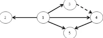
[image:6.595.213.384.338.401.2]Our methodology uses a modelling approach as a graph described in the ASDA (Assembly Sequences Definition Algorithm) algorithm defined by Demoly et al. [19], [20]. This modelling approach consists of defining a direct graph (as shown in Figure 2 with five components) of connections between parts of the chosen concept. In the graph, each node represents an elementary component and each link between two nodes indicates the presence of a relationship between two basic components. Two types of links (or arcs to a digraph) are represented: the contact relationships (represented by a solid line, arc (1,2) in Figure 2) and the precedence relationships between two parts without physical contact with each other (represented by dotted arc (3,4) in Figure 2) providing a constraint of order of assembly despite the lack of contact between two basic components. This graph is defined as “oriented” because it describes the order of positioning components. In summary, the nodes represent elementary components (component or subassembly) and are linked by relations oriented, representing the order of assembly of two parts. Subsequently, we will use interchangeably the term "node" or "component". From the FAST diagram, it is possible to add additional information on the graph by colouring with the same colour components in a single function or technical function.
Figure 2. Contact and precedence graph of product components
After building the graph, the first step of the algorithm is to verify that the graph has no circuit [21] to ensure that there is no human error in the definition of arc directions in the graph and to generate at least one eligible sequence (respecting all precedence constraints). From this graph we construct ordered sequences. In the graph, if we look only to precedence constraints identified by the arcs, it is possible to delete some "redundant" arcs of the graph [22]. For example, in the graph in Figure 2, the arcs (1.4) and (1.5) can be deleted because the precedence constraints between 1 and 4 and between 1 and 5 are obtained by transitivity. The component 4 must be assembled after component 3 which itself must be assembled after component 1. The next step of this algorithm is to identify in the graph, motifs of the same type as those proposed in the ASDA algorithm. The motifs considered are motifs with k components (here we restrict ourselves to k = 2 or k = 3) type series, intermixed, inclusive or parallel. The originality of our approach is to take into account the functional aspect of components to reduce the number of assembly sequences eligible in focusing our research on coloured motifs. A coloured motif is a set of components with the same colour and possibly components without colour. Our search for patterns is also guided by the precedence constraints. We research coloured motifs satisfying some properties. To formulate these properties, we adopt the notations given below. M represents the set of components of a motif. For a component i, we note Γ+
Figure 2
(i) (respectively Γ-(i)) the set of successors (respectively the set of predecessors) of the node i. In the graph in , we have, for example, Γ+(4)={5} and Γ-(4)={1,3}. By extension, we define Γ+(M) (respectively Γ
-( )
M U(i∈M) +( )
i+ = Γ
Γ
(M)) the set of successors (predecessors respectively) of a motif
and
( )
M U( )( )
i M i− ∈
− = Γ
Γ
We are looking for colorful designs that meet the following criteria:
• 1: the first component of the motif is coloured,
• 2: the other components of the motif are coloured or not,
Whenever a coloured motif is identified, we replace in the graph all nodes and their adjacent arcs constituting the motif by a single node labelled with the ordered sequence of nodes of the motif. This labelled node is then a sub-sequence in the overall sequence assembly. And we add arcs between this node and other nodes of the graph if there is a precedence relationship (with or without physical contact) between one of the components of the motif and another node. Condition 3 prevents the creation of cycle in the graph thus obtained. This operation of researching motif was repeated as many times as it is possible to "contract" the graph. The last step of the algorithm is to generate eligible sequences from the graph "contracted". To achieve this generation, we rely on a CSP model (Constraint Satisfaction Problem). A CSP is a problem modelled as a set of constraints imposed on variables, each of these variables taking values in a field. More formally, a CSP will be defined by a triplet (X, D, C) where:
• X = { X1, X2, ..., Xn
• D is the function that maps each variable X with its domain D (X), that is to say all the possible values of Xi;
} is the set of variables (unknown parameters) of the problem;
• C = {C1, C2, ..., Ck} is the set of constraints. Each constraint Cj is a relationship between certain variables X, restricting the values that these variables can take simultaneously.
In our case, we define the CSP (X, D, C) as a directed graph G = (V, E) where V represents all nodes in the graph (| V | = n) and E all arcs (| E | = m):
• X = {X1,X2,...,Xn
• D(X
} ;
1) = D(X2) = ...= D(Xn
• C1= { X
) = {1,n} ;
i
• C2={X
≠ Xj for any pair of nodes i and j in V};
j≥ Xi
Solving a CSP (X, D, C) consists to assign values to variables, such that all constraints are satisfied. Here, the resolution of the CSP provides us all ordered lists of nodes in the graph. To obtain the corresponding assembly sequences, the node is just replaced by its label, the latter corresponding to the number of a component or ordered components sub-sequence.
+1 for every arc (i,j) in E}.
4 CASE STUDY
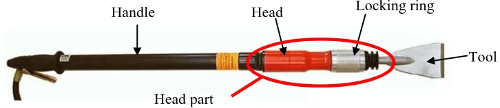
[image:7.595.132.495.486.565.2]To illustrate the methodology presented in the previous section, we will study the case of a range of pneumatic scrapers for cleaning surfaces such as a tiled floor. Our case study will be focused on the operative part of the range of tools, namely the head part (Figure 3).
Figure 3. Operative part of pneumatic scraper: the head part
4.1 Functional modelling of the modular product case study
As described in the FARD model, the study begins with an external functional analysis that allows defining the context. Only the “use” phase of the lifecycle of the products is studied because it is the most representative of the functions desired by customers. These pneumatic scrapers used to take off any type of coating on floors or walls. They operate with air under pressure and must respect the European standards. With all this information, we can then develop the service functions (SF) and constraints (Cons) of the use:
• SF1: allow the user to scrape the coating with pneumatic power
• Cons1: resist the environment
• Cons2: respect the standards
Quantification of the SF1 function can define the initial parameters from the functional design criteria, such as, for example: the tool energy between 15 Joules and 70 Joules, the supply pressure between 5.8 and 6.2 bars, etc.
Handle
Tool Locking ring
Head
SF1: allow the user to scrape the support with pneumatic
energy
TF2: Convert pneumatic energy
into mechanic energy
TF2.1 Receive tool
TF2.2 Move a hit lead
TF2.3 Receive pneumatic energy
TF2.4 Limit the noise
Figure 4. FAST diagram of the SF1 function, focused on the operative part (the head part)
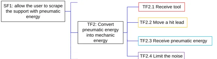
The next step is to decompose each service function in technical functions (TF), using a FAST diagram (Figure 4) allowing one to sketch the architecture of the modular product range, to the extent that: each technical function connected to the "mother" by binding "AND" may correspond to a future module, and each technical function connected to the "mother" by association "OR" may correspond to a module as an alternative solution or an optional module. For example, one of the technical functions of the service function SF1 is the module corresponding to the operating part “head”. This diagram should be built by a specialist person on this type of products because this step is very important for the product modularity. The diagram should also be checked by the entire team during the project.
4.2 Structural modelling of the modular product in the case study
4.2.1 Application of the Internal Functional Analysis (IFA)
[image:8.595.122.479.56.154.2]At this stage of applying the methodology, it is necessary to have a product concept in order to detail component design, for example, with a sketch drawn freehand shown in Figure 5 below.
Figure 5. Pneumatic scraper concept selected
[image:8.595.112.468.376.465.2]To simplify the sketch which follows, all parts will be represented by a number as presented in the table below.
Table 1. List of component for the head part
Parts Parts Parts
1 – Tool fitting 6 – Head O-ring 11 – Head 2 – Support ring 7 – Pin 12 – Lead
3 – Head ring 8 – Balls 13 – Noise reduction system 4- Locking ring 9 – Clip 14 – Head fitting
5 – Head spring 10 – Tool 15 – Head axis
In the previous section, an external functional analysis that meets the identified functions was performed. Starting from the concept definition, it is then possible to identify, through an internal functional analysis, which parts contribute to the realization of the main function and the desired performance value range as shown in Figure 6, which is the result of gradual decomposition and function mapping. The distribution of parts into different technical functions of the FAST diagram can also be executed. Indeed, the function SF1 is decomposed into technical functions which are further decomposed into sub-technical functions. Each function and sub-function then corresponds to a set or subset of the product. While modules are defined as matching units with the technical functions of the FAST diagram, modular architecture begins to take shape.
11
8 12
SF1: allow the user to scrape the support with pneumatic
energy
TF2: Convert pneumatic energy
into mechanic energy
TF2.1 Receive tool
TF2.2 Move a hit lead
TF2.3 Receive pneumatic energy
[image:9.595.88.511.61.181.2]TF2.4 Limit the noise
Figure 6. Determination of parts participating in the realization of the technical function TF2
In summary, the combination of technical functions and components allows the designer to define the beginning of the product architecture. Figure 6 presents the repartition of main parts into the technical function TF2, according to an "assembly directed" functional analysis of modular products. The architecture thus defined will guide the choice of the most suitable assembly sequence for "the head part", the operative part of the range of products.
4.2.3 Application of the algorithm to generate assembly sequences eligible
As explained in section 3.2, our algorithm is based on a graph of connections. At this stage of our approach, we apply, while the rewarding aspects of functional design, the concepts proposed by Demoly et al. [19] which allow to obtain the graph of connections (Figure 7) and which shows schematically the assembly structure of the concept.
Pièces 1 – Tool fitting 2 – Support ring
3 – Head ring
4- Locking ring
5 – Head spring 6 – Head O-ring 7 – Pin
8 – Balls
9 – Clip
11 – Head
12 – Lead
13 – Noise reduction system
[image:9.595.78.520.355.522.2]14 – Head fitting 15 – Head axis
Figure 7. Preview of Graph of connections, limited to the head part, the nodes and arcs are colored in connection with the technical functions
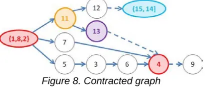
In the graph illustrated in Figure 7, we identify two motifs with a “series type” according to the criteria defined in section 3.2. The motif {1, 8, 2} is a “series” motif that begins with a colourful component (corresponding to the technical function TF2.1) without predecessor and all components of this motif have the same colour. Similarly, the motif {15.14} is a coloured motif. The graph in Figure 7 can then be contracted by deleting nodes 1, 8, 2, 15 and 14 and adding the nodes label {1,8,2} and {15.14}. We obtain the contracted graph in Figure 8.
Figure 8. Contracted graph
From this contracted graph, we create a CSP problem of 11 variables (for 11 nodes of the contracted graph) with the constraints C1 and C2 defined in Section 3.2. We use the language of logic constraint
Module level
[image:9.595.196.402.646.735.2]programming Gnu-Prolog [23] to establish and solve our problem, such as, for instance, to obtain the ordered assembly sequence following:
• Sequence 1: {1,8,2}, 11, 12, 13,{15,14}, 7, 5, 3, 6, 4, 9,
• Sequence 2: {1,8,2}, 7, 5, 3, 6, 11, 12, 13, 4, 9, {15,14},
• Sequence 3: {1,8,2}, 11, 13, 5, 7, 3, 6, 4, 9, 12, {15,14}.
4.2.4 Definition of the architecture and of the modular product range
At this stage, we have a set of eligible assembly sequences among which the planner will make a choice. Based on the experience and the assembly and technical knowledge of the planner, he can then choose the most suitable assembly sequence. In the case study, the best assembly sequence for the head part, selected by the planner, is the sequence 2: {1,8,2}, 7, 5, 3, 6, 11, 12, 13 , 4, 9, {15.14 }.
5 GLOBAL RESULTS OF THE ILLUSTRATION
Finally, we obtain a range of modular products, optimized in terms of meeting assembly and functional requirements dictated by the chosen assembly method and specified by the customer at the early stages of the project. Moreover, this range includes variants of a range of products made of interchangeable modules. These variant modules themselves are interchangeable. If we consider the head part, among the 4 sub-technical functions of the technical function TF2 (Figure 4), two subsets are standard. Only modules that correspond to sub-functions TF2.2 and TF2.3 offer alternatives. TF2.2 determines the strength of each product of the range and TF2.3 offers interfaces for connections to different handles. Furthermore components of each module can be assembled independently and the modules can be assembled at the end to make products. The assembly sequence defines the assembly plan for each component of the product and the modules relative to each other.
6 CONCLUSION AND FUTURE WORK
generate a range of modular products meeting the customer requirements of which the performance has been validated through simulation and re-launched for each product of the range.
REFERENCES
[1] Toussaint L., Demoly F, Lebaal N, Gomes S., PLM-Based Approach for Design Verification and Validation using manufacturing Process Knowledge, Journal of Systemics, Cybernetics and Informatics, 8, 1, 2010.
[2] Jose A., Tollenaere M., Modular and platform methods for product family design: literature analysis, Journal of Intelligent Manufacturing, 2005, 16, p371-390.
[3] Galsworth G. D, Smart, Simple Design, Essex Junction, Vermont: Oliver, 1994.
[4] Wilhelm B, Shimokawa K., Juergens U., Fujimoto T., Platform and modular concepts at Volkswagen - their effects on the assembly process. Transforming Automobile Assembly - Experience in Automation and Work Organization, Springer, Berlin, 1997, p. 146-156. [5] Baldwin C. Y., Clark K. B., Managing in the age of modularity. Harvard Business Review,
1997, p84 - 93.
[6] Huang C.-C., Kusiak A., Modularity in design of products and systems, IEEE Transactions on Systems, Man and Cybernetics, Part-A: Systems and Humans, 28, 1, 1998, p66–77.
[7] Hölttä-Otto K., Modular product platform design, Thesis, 2005.
[8] Stone R. B., Wood K.L., Crawford R.H., A heuristic method for identifying modules for product archotectures, Design Studies, 21, 1, 2000, p5-31.
[9] Dahmus J. B., Gonzalez-Zugasti J.P., Otto K.N., Modular product architecture, Design Studies, 22,5, 2001, p409-424.
[10] Ulrich K., The role of product architecture in the manufacturing firm, Research Policy, 1995, 24, p419-440.
[11] Pandremenos J., Paralikas J., Salonitis K., Chryssolouris G., Modularity concepts for the automotive industry: A critical review, CIRP Journal of Manufacturing Science and Technology, 2009, 1, p148-152.
[12] Sako M., Murray F., Modules in Design, Production and Use: Implications for the Global Automotive Industry, MIT IMVP Annual Sponsors Meeting, Cambridge, Massachusetts, 1999. [13] Agard B., Tollenaere M., Design of product families: methodology and application, In
International Conference on Engineering Design, ICED’03, Stockholm, August 2003, pp 209-210.
[14] Salvador F., Toward a Product System Modularity Construct: Literature Review and Reconceptualization, IEEE Transaction on Engineering Management, 54, 2007, p219-240. [15] Stevens W. P., Myers G. J., Constantine L. L., Structured design, IBM Systems Journal, vol. 13,
1974, pp. 115–139.
[16] Stone R. B., McAdams D. A., Kayyalethkkel V. J., A product architecture-based conceptual DFA technique, Design Studies, 25, 3, 2004, p301-325.
[17] Barnes C.J., Jared G.EM., Swift K.G., Decision support for sequence generation in an assembly oriented design environment, Robotics and Computer-Integrated Manufacturing, 20, 2004, p289-300.
[18] Bytheway C. W., FAST Creativity & Innovation: Rapidly Improving Processes, Product Development and Solving Complex Problems, Hardcover, ISBN: 1-932159-66-5 2007. [19] Demoly F., Yan X.T., Eynard B., Rivest L., Gomes S., An Assembly-Oriented Design
Framework for Product Structure Engineering and Assembly Sequence Planning, Robotics and Computer-Integrated Manufacturing Journal, 27, 1, p33-46, 2011.
[20] Demoly F. Gomes S., Eynard B., Rivest L., Sagot J.C., Assembly-oriented product structure based on preliminary assembly process engineering, In International Conference on
Engineering Design, ICED’09, Vol. 7, Stanford, August 2009, pp 161-172. [21] Gondran M., Minoux M., Graphes et algorithmes, Eyrolles, 1995.
[22] Fruhwirth T., Abdennadher S., Essentials of Constraint Programming
[23]