Abstract—This paper presents a fast selective harmonic current mitigation strategy for inverters with active power filter capabilities based in synchronous reference frames and two-degrees-of-freedom internal model controllers. The advantage of this control strategy over the conventional PI solution is a significant increase in the speed of harmonic detection and mitigation. Furthermore, this control strategy reduces the computational burden when applied in a digital controller. These characteristics make this strategy desirable for applications where fast/harmonic detection and mitigation are needed. Mathematical analysis and simulations are presented to corroborate the performance of the proposed controller strategy. Finally, the results of this proposal are verified in a 1kW 3-phase multifunctional inverter with harmonic compensation capabilities up to the 17th harmonic.
Index Terms— Multifunctional Inverter, Active Power Filter, fast harmonic mitigation, Synchronous Reference Frame.
I. INTRODUCTION
CTIVE power filters have the advantage of providing
dynamic compensation of harmonic currents in the ac network. The active power filtering feature can be added to a voltage source converter. This converter turns into a multifunctional inverter (MI) able to supply active/reactive power to the grid, as well as harmonic currents for power quality improvements [1].
Manuscript received April 14, 2016; revised July 25, 2016 and December 31 2016; accepted February 06, 2017. This work was supported by EPSRC SUPERGEN Wind Programme under Grant EP/L014106/1.
D. Campos-Gaona, O. Anaya-Lara, and W. E. Leithead are with the Department of Electronic and Electrical Engineering, University of Strathclyde, Glasgow G1 1XW, U.K (email: [email protected], [email protected], [email protected]).
R. Peña-Alzola was with the University of British Columbia, Canada and now he is with the Department of Electronics, University of Alcala, Alcala de Henares, Madrid 28805, Spain (e-mail: [email protected]).
M. Ordonez is with the Department of Electrical and Computer Engineering, University of British Columbia, Vancouver BC V6T 1Z4 Canada (e-mail:[email protected]).
J.L. Monroy-Morales is with the P.G.I.I.E. department, Instituto Tecnonogico de Morelia, Mich., 58120 Mexico (e-mail: jlmonroy [email protected])
The ability to dynamically select the number and magnitude of the harmonics to compensate enables the most economical use of the MI, since the harmonic compensation can be tuned to address the most problematic harmonics in the ac network, avoiding unnecessary investment in control bandwidth and converter ratings [2]. Furthermore, selective harmonic compensation enables an increase in robustness when filtering, since parameter deviation can be easily taken into account when tuning the individual harmonic controllers [2],[3].
Some ac loads provide fast transient harmonics, such as when the current is drawn by an electric drive during startup, acceleration [4], during fast speed control adjustment in electric drives [4] or in the traction system of high speed trains [5]. During those events, the faster the harmonic compensation is carried out, the better for the optimal performance of the converter.
The control techniques for MIs with selective mitigation of harmonics using fixed switching frequency can be divided in two main branches:
1) The proportional-resonant based controllers
Proportional-resonant (PR) based controllers [6]-[8] are able to follow sinusoidal harmonic references at their respective resonant frequencies without steady state error by introducing an infinite gain at the desired resonant frequency. Additionally, PR-based controllers provide fast response for set point changes.
The disadvantages of PR-based controllers are that attaining adequate controller tuning and stability is a complex process; moreover, the controller resonant frequency should be well tuned to the reference frequency, as the infinite gain band is narrow, making this control technique susceptible to grid frequency variations [9]. Non-ideal PR-based controllers use second order generalized integrators, which results in wider resonant band but with the penalty of an increased tracking error [10].
2) The synchronous reference frames (SRF) based controller.
This type of controller applies several synchronous d-q
harmonic frames and low pass filters to detect the harmonic currents. The control of the harmonic currents coming from the MI is carried out using PI controllers.
The advantage of using SRF-based controllers is that they
Fast Selective Harmonic Mitigation in
Multifunctional Inverters using Internal
Model Controllers and Synchronous
Reference Frames
D. Campos-Gaona
Member, IEEE
, R. Peña-Alzola
,
J.L. Monroy-Morales, M. Ordonez,
Member, IEEE,
O. Anaya-Lara,
Member IEEE
, and W.E. Leithead
enable individual harmonics to be measured and controlled using dc signals, where easy-to-tune PI controllers can provide stable control with no tracking error; additionally, an active power filter using SRF-based controllers is immune to grid frequency variations.
The main disadvantage of using the SRF-based controllers for harmonic mitigation is that it results in slow harmonic detection/compensation, because of the delay produced by the low pass filter in the SRF control topology, and also that the use of multiple synchronous d-q harmonic frames and low pass filters produces an increased computational burden [11]-[13].
This paper proposes a solution that overcomes the slow harmonic detection/compensation of SRF-based controllers, and eliminates delays to accelerate harmonic compensation without affecting the positive properties of the SRF-based controllers. This is achieved by removing the low pass filters from the conventional SRF control topology and replacing the PI controllers with two-degrees-of-freedom internal model controllers (2DF-IMC). By doing this, the 2DF-IMC of the individual harmonic control loops are able to simultaneously track the harmonic current set-point without delay. Additionally, the 2DF-IMCs collectively reject the ac disturbances produced by the operation of a filter-less SRF in the dc domain (see section IV.B).
When 2DF-IMC is used along with SRF, one obtains, among other benefits, a dramatic increase in the speed of harmonic detection and mitigation, since the proposed controller configuration does not require low pass filters to detect and compensate the harmonics in the SRF.
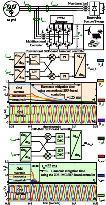
Fig. 1 shows a schematic diagram of the proposed solution and its effects in the speed of harmonic mitigation when compared with the conventional SRF-based controller. As seen in Fig. 1 a) and c), the ac grid currents (i.e. the currents seen by the ac grid after the node connecting the MI and the non-linear load) contain several harmonics of different magnitude; these harmonics are produced by a non linear load. At t=0.4 seconds the MI begins to cancel the harmonic currents from the non linear load by injecting harmonic currents in the point of common coupling. When the conventional SRF-based controllers (based on PI controllers and low pass filters) are used, the time to totally cancel out the harmonics in the grid current and to leave a sinusoidal waveform is 125 ms, as seen in Fig. 1 a) and b), whereas when using the 2DF-IMC SRF-based controllers the total cancellation of harmonic currents is carried out in just 22ms as seen in Fig. 1 c) and d).
This paper is organized as follows: section II reviews the theory of operation of the conventional SRF-based harmonic and the past/current research efforts to speed up its harmonic detection capabilities. Section III describes the theory of the 2DF-IMC and the control rule derivation for the different 2DF-IMCs of the MI. Section IV analyzes the implications of removing the low pass filters from the conventional SRF controller and the positive effects of using the second-degree-of-freedom feature of the 2DF-IMC in the MI realization. Section V presents simulations results of the proposed
controller. Section VI presents the experimental validation of the proposed controller in a 1kW MI with harmonic mitigation capabilities up to the 17th harmonic. Finally section VII presents the conclusions of this investigation.
Fig. 1 Harmonic mitigation time response comparison between the conventional harmonic controller and the 2DF-IMC controller.
II. HARMONIC DETECTION/MITIGATION USING
CONVENTIONAL SRF-BASED CONTROLLERS
The conventional process of detecting and mitigating harmonic load currents using a MI with SRF is shown in Fig. 2. As seen in Fig. 2, the load current is measured and fed to the several d-q SRFs rotating at different harmonic frequency (p.e. 5th, 7th, 11th etc). The d-q SRF is a mathematical transformation that converters a three phase ac signals into an equivalent dc d-q signal. Each d-q SRF provides the dc d-q equivalent components of its rotating harmonic frequency plus an ac signal (product of the fundamental/harmonic currents of different frequency of that of the rotation of the d-q SRF). In order to obtain the dc values of the harmonic d-q signal, a low pass filter is used to
[image:2.595.319.532.134.547.2]eliminate any ac component at the output of the d-q SRF. The same procedure is used for the MI current .
Fig. 2 MI with conventional SRF-based controllers
The filtered d-q components of are used as set points for the PI controllers. The PI controllers generate, as a control action, a modulator signal that would produce harmonic currents of magnitudes that match those of the load, but in opposite polarity. Thus, the load harmonic currents would cancel out the MI harmonic currents at the point of common coupling.
The conventional SRF-based controllers for harmonic detection/mitigation have been widely used in recent developments [14]-[19]. Needless to say, all these developments make use of the conventional approach for SRF-based controllers where low pass filters are used to detect/mitigate harmonic currents, which results in a slow harmonic compensation.
Some research has been carried out to speed up the detection/mitigation of d-q harmonic currents using conventional SRF. The investigation in [18] uses low pass filters based in the moving average technique at a cut-off frequency of 100Hz, which would enable a harmonic detection within half a cycle however, this solution still requires the use of a low pass filters with increased number of memory allocations and is sensitive to grid frequency variations. Other research focuses on eliminating the use of the low-pass filters in the conventional SRF-based controllers by implementing a harmonic d-q transformation that averages the values of the harmonic d-q signals by applying a recursive algorithm within the transformation [20]. However, this technique requires an extra workaround to avoid a frequency drift effect caused by grid frequency variations.
Evidently, a solution that provides the same robustness of detection and control of harmonic currents found in the conventional SRF-based controllers, but with faster dynamic performance, is highly desirable for MI applications. This paper shows that such a solution can be obtained by removing the low pass filters from the conventional SRF architecture and counteracting the negative effects of doing this by using 2DF-IMC. The key factor for the stable functioning of the filter-less realization of the SRF is the enhanced load disturbance rejection provided by the 2DF-IMC. This is analyzed next.
III. THEORY AND IMPLEMENTATION OF 2DF-IMC The internal model control (IMC) technique relies on the “internal model” principle, the philosophy of which states that a control action over a plant can be achieved only if the control system includes, either implicitly or explicitly, some representation of the process to be controlled. Information about the configuration of the IMC controller structure can be found in [21] and [22].
The IMC design procedure requires, for a realizable control, a low pass filter in cascade to the IMC controller, otherwise the IMC controlled transfer function would include the use of pure differentiators. The filter is of the type
(1) where the order of the filter, , is chosen according to the order of the plant , and can be interpreted as the closed loop bandwidth of the control system.
Since, ideally, all the plant parameters are represented within the IMC controller structure, the only variable to adjust in the IMC controllers is the closed loop bandwidth of the control system ( ).
Fig. 3 shows the structure of the IMC controller modified to graphically group the controller section and the plant section in the closed loop system. By doing this, the structure of the IMC controller resembles that of a PI controller for first order plants. Also, Fig. 3 includes the representation of an inner feedback loop of gain in the plant, which is designed to provide a second degree of control freedom. This additional degree of control is used to speed up the natural response of the plant by moving the pole of the plant away from the origin within the negative side of the real axis. The additional degree of control freedom greatly improves the load disturbance rejection characteristic of the plant which, by itself, is independent of the set-point tracking controller.
The load disturbance rejection feature of the 2DF-IMC is specifically designed to reject dc disturbances with 0 steady state error. This feature is the key factor for the filter-less realization of a SRF controller since, as it will be explained in section IV, the negative effects of removing the low pass filters from the conventional SRF control structure, is a control loop polluted with ac harmonic signals. Nevertheless the 2DF-IMC is able to deal-with this harmonic pollution in the dc domain.
By adding a feedback loop of gain , the transfer function of the improved plant is
[image:3.595.309.546.643.737.2](2) where is the improved transfer function of the plant.
Fig. 3: The 2DF IMC configured as a PI controller
inv
i
load i
( )
L s
( )
L s
( ) / z
L s s z ( )
G s
R
R
1( ) ( ) / 1 ( ) 1/ ( )
M s G s G s R G s R
( )
Since all the different process to control in the MI are of first order type, the derivation of their respective IMC controllers can be generalized by the IMC control transfer
function (considering that is the model of ),
as shown in (3)
(3)
One way to define as in function of is to make the plant load disturbance rejection as fast as the controller's set-point closed loop dynamics. To achieve this, the pole is set in the inner feedback loop to match the pole of the closed loop transfer function from the disturbance to output signal of the plant .
The relationship between the rise time, , and the closed loop bandwidth of the controller is given by
A. 2DF-IMC control of fundamental and harmonic currents
The equations defining the dynamics of the d-q fundamental and harmoniccurrents between the MI and the ac grid are:
(4)
where and are, respectively, the equivalent resistance and
inductance between the MI and the ac grid, are
the average d-q current components of the harmonic, and are the d-q components of the harmonic of the average voltages generated by the MI and where and are the d-q voltage components of the ac grid.
The transfer functions between d-q MI fundamental and harmonic currents and the d-q MI fundamental and harmonic voltages can be represented by the same equation if the
cross-coupling terms ( and ), and the grid voltage
components, ( and ) from (4) are considered
disturbances, not present during the calculation of the d-q
current control, but instead being numerically compensated by a feedforward loop, as shown in Fig. 4. Hence, the MI current-to-voltage relationships in the d-q frame is given by
(5) If an inner feedback loop of gain is added to (i.e a second degree of control freedom, as shown in (2)), an enhanced transfer function of the following type is obtained:
(6) The inner feedback loop is implemented in the plant by making the input signal to the plant equal to
(7) where is the output of the IMC current controller
, which, accordingly to (3), is
(8)
where is the bandwidth of the closed loop d-q current control system. From (8), one can deduce the equivalent PI controller constants of the IMC controller constants as
. (9)
The value of is selected to make the load disturbance rejection of the current plant to be as fast as the closed loop transfer function. By selecting a value of
(10) the relationship between the output voltage of the MI and
disturbance becomes
(11)
As seen in (11), the disturbances are rejected by the plant and the controller with the same time constant, which in turn depends on .
B. 2DF-IMC control of the dc voltage
The equation describing the dynamic behavior of the dc voltage is presented in (12) (neglecting the resistive losses and the energy stored in the inductance)
(12)
where is the capacitance of the dc circuit and is the active power consumed/generated by the load/generator connected to the dc bus.
In order to work with linear expressions (assuming is constant), the output variable of the dc-plant is selected to be the square of the capacitor voltage (i.e. a representation of the energy of the capacitor w). Thus, selecting , and considering a disturbance, not present during the calculation of the voltage controller, the transfer function of the dc-plant can be presented as:
(13) A seen in (13), has a pole at the origin, which makes it very susceptible to disturbances.
Following the procedure for designing a 2DF-IMC presented in the previous section, the PI controller constants and of the IMC and the feedback loop gain needed
to make the plant load disturbance rejection as fast as the controllers are calculated as:
(14)
where is the bandwidth of the closed loop control system.
In order to effectively reject and avoid an excessive transient change in with respect to the controller set-point, one can calculate the maximum error for a step-like disturbance of and select the controller bandwidth accordingly. The relationship between the maximum error of
, , and is defined, for a given , as [21]: (15) ( )
F s M s'( ) M s( ) 1
1 1
( ) ' ( )
( ) ' ( ).
1 ( ) ' ( ) '( )
L s M s
F s M s
s
L s M s M s
R R ( ) d s ( ) y s r T
2.2 / (rad).Tr
_ _ _ _ _
_ _ _ _ _
/ /
n d inv n d n d s n q d
n q inv n q n q s n d q
v ri ldi dt li v v ri ldi dt li v
r l
_ and _
n d n q
i i
n
_ _ n d inv
v
v
n q inv_ _n
d
v vq
_ s n q
li
s n dli
_d
v
v
q
( ) 1/ .
i
G s ls r
i
R G si( )
1 / (
( ) )
i i
M s ls r R
_ ( ) _ '( ) ( )
n inv n inv n i
v s v s i s R
_ '( ) n inv v s ( ) i F s
( ) /i i i i
F s l rR s
i
,
i i i i i
Kp l Ki r R
i
R
i
R
i i
R l r
( )
i
d s
2
_inv( ) / i( ) / i .
v s d s s l s
( ) i d s i dc v
2 1 _ 3 2 2 dcload d d dv
c
P v i
dt
c Pload
d
v
2 dc
w v
load
P
( ) / ( )d w( ) 3 / ( ).d
w s i s G s v cs
( ) w G s w
Kp Kiw
2 dc
w v
/ (3 ), , / (3 ).
w d w w
w c v Ki Rw Rw w d
Kp c v
w
w v
dc2load
P
w
load
P w
w
Ew_ max w Pload
_ max 2 exp( 1) / .
w load w
Thus, by using (15) the minimum value of can be calculated to prevent the variable from increasing or decreasing from a defined margin.
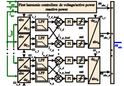
Fig. 4 shows the full schematic diagram of the MI controller loops for the first harmonic controllers. The schematics of the current controllers shown in Fig. 4 can also be use to describe harmonic current controllers since they share the same structure and constants, as explained in section III.A.
Fig. 4 Schematic diagram of the MI controller loops for the first harmonic controller.
C. 2DF-IMC Bode plots analysis
Using and the passive element values in Fig.
8, the bode plots of the dc-plant, the enhanced dc-plant with an inner feedback loop, the open loop transfer function and the closed loop transfer function of the dc-plant controller are presented in Fig. 5.
[image:5.595.49.289.189.335.2]As seen in Fig. 5 the bode plot of the dc-plant ( ) is the one of that of a pure integrator, as stated by (13). However when the inner feedback loop is added to the dc-plant ( ), an artificial pole is placed at 183 rad, which is equal to the pole of the closed loop control system. The fact that the enhanced dc-plant and the closed loop system share the same pole at 183 rad shows that natural disturbance rejection of the dc-plant is now as fast as the closed loop dynamics, this behavior is essential for the proper functioning of the 2DF-IMC based SRF controller as it will be explained in section IV.
Fig. 5. Bode plot of the systems in the dc plant
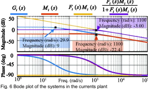
Using and the passive element values in Fig.
8, the bode plot of the currents plant, the enhanced current plant, the open loop and the closed loop transfer functions of the current controller are presented in Fig. 6.
Fig. 6 Bode plot of the systems in the currents plant
As seen in Fig. 6 the bode plot of the current plant ( ) is the one of that of a first order system, as stated by (5). However when the inner feedback loop is added to the current plant ( ), the pole in the plant is moved from 29.9 to 1100 rad, which is equal to the pole of the closed loop system. The fact that the enhanced current plant and the closed loop system share the same pole at 1100 rad shows that natural disturbance rejection of the current plant is now as fast as the closed loop dynamics, this behavior is essential for the proper functioning of the 2DF-IMC based SRF controller as it will be explained in Section IV.
IV. ANALYSIS OF THE FILTER-LESS SRFIMPLEMENTATION
A. Propagation of harmonics in a filter-less SRF This section explains how the harmonic signals propagate inside the control loops of a SRF when the low pass filter stage is removed from the controller structure.
Equation (16) presents the generalized harmonic dq0
transformation used in the SRF technique to obtain the d-q components of the harmonic. This transformation is based on the modified dq0 transformation, in which a 3 phase sinusoidal signal of magnitude 1 and no phase shift would
produce a value of (this transformation is similar
to the one found in SimPowerSystems and it is used in all the simulations and experimental results in this paper). The transformation is
(16)
where represents the sequence of the
harmonic and is reflected in (16) as an algebraic sign. The application of to a 3 phase current signal with harmonic content would produce, as an output, a dq0 signal comprising the dc d-q components of the harmonic, plus an ac component, with the rest of the harmonics moved in frequency, depending on the sequence of the harmonic and
w 2
dc w v
183 rad
w
( )
w
G s
( )
w
M s
1100 rad
i
( )
i
G s
( )
i
M s
n
T
n
1, 0
d q
sin sin 2 / 3 sin 2 / 3
2
cos cos 2 / 3 cos 2 / 3
3
1/ 2 1/ 2 1/ 2
n s n s n s
n n s n s n s
n t n t n t
T n t n t n t
sign sin 2 / 3n n
n
n
T
n
[image:5.595.47.290.577.739.2]the sequence of the rest of the harmonics. Mathematically this is:
(17)
where and are the harmonic d-q signals
respectively. is the phase shift of the harmonic, is the magnitude of the harmonic, is the magnitude of the k
harmonic current, is the synchronous frequency in radians, is the time, is the phase shift of the k harmonic,
and represents the sequence of the k
harmonic and is reflected in (17) as an algebraic sign.
If the ac components of the d-q currents in (17) are allowed to propagate in the control loops then the controller output will become a hybrid signal composed of a dc part (the useful control action) plus a ac part (the ac harmonic pollution). The details of the propagation of the ac component of the d-q
signal throughout the control loops is analyzed mathematically in section VIII.A, where it is proven that for constant harmonic input the controller produces a constant single-harmonic output. The 2DF-IMC ac output components would add up and, together, would be processed by the inverse transformation , eventually being fed as modulator signals to the MI.
The modulator signal fed to the MI by a filter-less SRF is a hybrid waveform composed of 2 parts: 1) A useful control action (the dc dynamics of the fundamental and harmonic d-q
current loops) plus 2) constant harmonic disturbances (product of using filter-less SRF) which are meaningless (even dangerous) for control purposes. However, these ac disturbances can be fully rejected in the dc domain with 0 steady state error when using 2DF-IMC. This is explained, in detail, in the following section.
B. Effects of a 2DF-IMC in a filter-less SRF
As dangerous at it may seem, the constant ac harmonic disturbances produced by the filter-less 2DF-IMC are actually innocuous for a selective harmonic compensator based on the 2DF-IMC. The reason for this is that an n constant ac harmonic disturbance, produced by any given 2DF-IMC controller of the system, is reflected as a constant dc signal disturbance in the 2DF-IMC dedicated to the control of the n
harmonic (see VIII.A).
Since the 2DF-IMC is specifically designed to reject step-like, constant dc disturbances, is an ideal fit to compensate the ac disturbances produced by the other 2DF-IMC controllers with the same robustness and speed of response of its set-point tracking characteristics, since they will be reflected as a dc disturbance signal. Because of this, an array of 2DF-IMCs dedicated to compensating individual harmonics, will collectively compensate the ac disturbances produced by one another as fast as they track a set point change.
The result of the collective control action of all the 2DF-IMC is simply a fast collective harmonic compensation, where
the difference between the disturbance rejection and the set-point tracking dynamics is indistinguishable.
Since the disturbances produced by the ac components in the filter-less 2DF-IMC are readily compensated by the rest of the harmonic SRF controllers, and no filter is present in the SRF controller architecture, the set-point/disturbance rejection closed loop current dynamics (for both fundamental and harmonic currents) can be selected to be as fast as necessary, being limited only by the desired controller robustness, the accuracy of the internal model, the sampling frequency and the quantization errors. A more detailed explanation of the sensitivity of the IMC controller robustness to parameter uncertainty is provided section VIII.B.
Here it is important to highlight that if the controller inside a filter-less SRF is not actively damping external disturbances, (e.g. a conventional PI controller), then, collective input of disturbances would produce instability in the control loops (especially in the case of the poorly damped process of ) . This is because the first-harmonic signals that propagate throughout the non-first harmonic controllers eventually become a large exogenous dc disturbance added to the control action of the controllers dealing with first-harmonic-based variables.
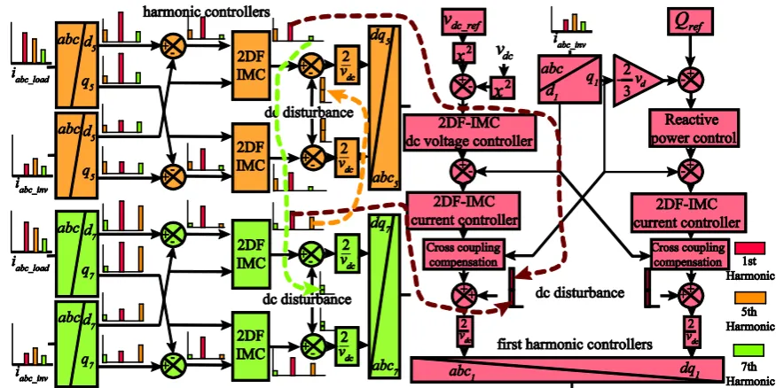
Fig. 7 shows a diagram of the collective disturbance rejection and harmonic control of the filter-less 2DF-IMC harmonic controllers. The colored spectrum shown next to some sections the controllers in Fig. 7 reflects how the harmonics propagate throughout the controller. As seen in Fig. 7, some of the harmonics that enter from the d-q
transformations propagate at different frequencies and magnitudes throughout the control loops, eventually becoming an ac disturbance at the output of the harmonic controller. These ac disturbances are reflected as dc disturbances in another controller loop (as shown by the dotted connecting arrows) where the disturbances are rejected completely with 0 steady state error.
V. SIMULATIONS
Fig. 8 shows a diagram of the simulated network, a MI is connected in parallel to a non-linear load consisting of a 3-phase diode rectifier. The control parameters are: closed loop
bandwidth of the controller , closed loop
bandwidth of the fundamental/harmonic current controllers .
Fig. 9 shows the simulation results when the MI in Fig. 8 enables its harmonic compensation capabilities at t=0.4 seconds. As seen in Fig. 9 a) and b), when the harmonic compensation is enabled, the d and q components of the different harmonics in (up to the 17th harmonic) are reduced by 95% in just 14 ms ( ), and are being totally mitigated in 22 ms. This is reflected as a fast harmonic compensation in , as seen in Fig. 9 c). This speed of harmonic compensation is as fast as the fastest controllers based in PR reported in open literature (see [3],[7]).
The benefits of using 2DF-IMC based SRF are not limited to fast harmonic compensation only, but are extended to fast harmonic detection as well, (because of the filter-less
_
1, dc component
ac component
_
1, dc component
ac componentl
cos( ) cos
sin( ) sin
n d n n n k k k n k s k k k n
n q n n k k n k s k k k n
i i i n k t
i i i n k t
_
n d
i
i
n q_ nn
n in
n ik s
t k
sign sin 2 / 3
k k
1 n
T
dc
v
2
dc
w v w 183 rad
_ 1100 rad
i h
g r i d
i
5%
s
t
g r i d
implementation). In order to provide further evidence of the fast detection and mitigation of harmonic content, Fig. 10 shows the simulation results of the MI when the three phase rectifier (the non-linear load) is connected for a small period of time to the ac grid.
[image:7.595.76.514.83.302.2]Fig. 8 Test network of simulation results.
Fig. 9-Simulation 1: Result of the fast harmonic compensation of the 2DF-IMC based SRF
As seen in Fig. 10 b), the harmonic detection/mitigation capabilities are fast enough to compensate harmonic distortion
in a period of 22 ms. Also, when the non-linear load is disconnected from the ac grid, the MI takes little time to detect this change and stop the provision of harmonic current to the point of common coupling. This can be better appreciated in Fig. 10 c).
Fig. 10 Simulation 2: Harmonic detection/compensation capabilities of transient harmonics of the 2DF-IMC based SRF
As explained in section IV, the increased load disturbance rejection of the 2DF-IMC architecture is the key factor in providing stable control in a filter-less SRF. In order to illustrate the increased load disturbance rejection characteristics of the 2DF-IMC, Fig. 11 shows the behavior of the modulator signals of the MI, and the effect of disturbances on the dc voltage (the most load disturbance sensitive system) for the transient harmonic test presented in simulation 2.
As seen in Fig. 11 a), the collective disturbances generated by the filter-less SRFs produce a transient peak on the modulator signals. The disturbances on the modulators, although constant in nature, are quickly rejected by the second degree of freedom of the IMC architecture of all the current controllers (fundamental and harmonic). The effects of the modulator disturbance peak on the grid currents are shown in Fig. 10 b) and the effect of the modulator peak disturbance on the dc voltage is shown in Fig. 11 b). In both cases, the action
[image:7.595.48.284.380.705.2] [image:7.595.315.541.387.533.2]of the second degree of freedom of the IMC controller prevents the control variables from suffering excessive change with respect to their set-point value.
Fig. 11 Effects of the collective ac disturbances produced by the filter-less SRFs on the modulator signal and dc voltage of the MI
VI. EXPERIMENTAL RESULTS
A 1kW 3-phase MI connected in parallel to a non-linear load consisting of a 3-phase diode rectifier, in a circuit configuration and parameters as shown in Fig. 8, with the same control parameters as those presented in section V but
with , is used to corroborate
experimentally the performance of the proposed 2DF-IMC-based SRFs. The digital control of the MI is carried out by a 32 bit F28335 DSP from TI at a sampling/switching frequency of 16 KHz.
[image:8.595.56.282.117.244.2]Fig. 12 shows the harmonic content in the ac grid currents produced by the 3-phase diode rectifier when no filtering is performed. As seen in Fig. 12 the harmonic pollution of the currents waveform is mainly composed of the 5th to 13th harmonics.
Fig. 12 Experimental harmonic content in the ac grid currents produced by the 3-phase diode rectifier
Fig. 13 shows the behavior of the grid currents when the 3-phase rectifier is connected to the ac circuit and the 2DF-IMC based active power filtering is operational. As seen in Fig. 13 a) and b), the grid currents are harmonic free (up to the 17th harmonic). This can be further corroborated by the spectrum presented in Fig. 13 c). The zoomed out representation of the grid currents shown in Fig. 13 b) shows a speed of harmonic compensation as fast as that presented in simulations.
To further illustrate the harmonic compensation capabilities of the experimental setup, Fig. 14 shows a detailed view of the currents, before (load currents) and after (grid currents) the harmonic compensation. As seen in Fig. 14, the speed of detection/mitigation of harmonic currents by the proposed 2DF-IMC controller is as fast and as stable as in the simulations. This corroborates the proper functioning of the proposed algorithm under realistic scenarios.
Fig. 13 Experimental results of the fast harmonic compensation of the 2DF-IMC based SRF
[image:8.595.51.287.452.556.2]In order to compare the performance of the 2DF-IMC based SRF with the conventional SRF-based controllers, the experimental performance of the active power filter using low pass filters and PI controllers tuned using the technical optimum technique is presented next. In the technical optimum tuning technique the integration gain cancels the time constant. The proportional gain is then adjusted so the overshoot is of around 5%. The resulting closed loop bandwidth can be ideally selected to be 1/20 times the sampling frequency. The technical optimum procedure, however, does not have a precise control on the amount of available damping as happens with the 2DF-IMC; neither can it achieve the ideal closed loop bandwidth because of the delay in the setpoint/measured signals produced by the low pass filter dynamics. Because of this, the experimental results show a slow harmonic compensation when compared with the 2DF-IMC controllers.
Fig. 14 Detailed view of the currents before and after harmonic compensation when using the 2DF-IMC based SRF.
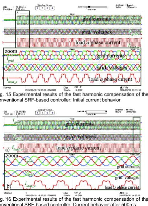
Fig. 15 and Fig. 16 shows the behavior of the grid currents when the 3-phase rectifier is connected to the ac circuit and the conventional SRF-based controller is operational. The parameters of the PI controllers are: 5th and 7th harmonic
controllers constants , 11th harmonic
controller constants , 13th harmonic
controller constants the low pass filters
used for the harmonic controllers is of the second order Butterworth type with a cutoff frequency of 60Hz and a damping factor of 0.707.
Fig. 15 shows a zoomed view of the initial behavior of the grid currents and Fig. 16 shows a zoomed view of the behavior of the grid currents after 500 ms.
40V rms
grid
v vdc 250V l r/
3.08, 91.06
Kp Ki
2.31, 68.75
Kp Ki
1.54, 45.83
[image:8.595.307.553.469.577.2]Fig. 15 Experimental results of the fast harmonic compensation of the conventional SRF-based controller: Initial current behavior
Fig. 16 Experimental results of the fast harmonic compensation of the conventional SRF-based controller: Current behavior after 500ms
As seen in Fig. 15, the harmonic detection/compensation capabilities for the conventional SRF-based controller are slow with only a partial harmonic compensation after 8 cycles of the fundamental ac current. Fig. 16 shows that after 500 ms the harmonic compensation has been carried out, however this delay time is much higher than the one obtained with the 2DF-IMC controller.
VII. CONCLUSIONS
This paper presents a fast harmonic detection/mitigation strategy for MIs using filter-less SRF and 2DF-IMC controllers. The filter-less implementation of the SRF enables harmonic currents to be detected/mitigated with remarkable rapidity compared with conventional SRF solutions. The key to implementing the filter-less SRF without affecting the stability of the converter is to deal with the collective disturbances, produced by the filter-less SRF, by using a 2DF-IMC structure.
By using the 2DF-IMC, a reduction of the computational burden is obtained because of the elimination of the low pass filters in the SRF harmonic detection/mitigation stages. Also, since the 2DF-IMC use the plant parameters to analytically calculate the control constants; the controller tuning process is reduced to the selection of only one variable: the speed of response of the closed loop system. Finally since the 2DF-IMC is based in the SRF structure, the harmonic detection/mitigation process is immune to grid frequency variations.
The use of a SRF with 2DF-IMC allows taking advantage of all the benefits of the SRF solution, with detection-mitigation speed of a PR solution, without sacrificing stability or controller robustness. These positive attributes make the 2DF-IMC-based SRF controller highly desirable for industrial applications.
VIII. APPENDIX
A. Mathematical analysis of harmonic propagation within the 2DF-IMC controller loop
A 3-phase current signal with a 7th harmonic component is used in this section in order to analyze the harmonic propagation within the 2DF-IMC control structure. This current is described mathematically by
(18)
and produces the following d-q signals for a 7th harmonic SRF (19)
If the ac components of the d-q currents in (19) are allowed to propagate in the control loops, then the 2DF-IMC would produce an ac output signal of the type
(20)
Solving the integral terms in (20) and using the trigonometric identities
(21)
the following ac expressions are obtained
(22)
where, using (9) and (10)
(23) Equation (23) evidences that the ac output signals of the
2DF-IMC (i.e. ) are scaled by a factor of
and displaced by an angle of . In the same manner as the
ac signals , any additional ac harmonic signal
fed to the 2DF-IMC will produce an output ac signal of
magnitude and phase displace. This applies to any ac harmonic signal fed to the 2DF-IMC.
The fact that the ac output components of the 2DF-IMC are of the type described by (22), where the magnitude and phase displacement is the same for both the d and q components (i.e. and ) means that a single-harmonic input to the
1 1 7 7
1 1 7 7
1 1 7 7
sin sin 7
sin 120º sin 7 120º
sin 120º sin 7 120º
a s s
b s s
c s s
i i t i t
i i t i t
i i t i t
7 _ 7 7 1 1
dc component ac component
7 _ 7 7 1 1
dc component ac component
cos( ) cos(6 )
sin( ) sin(6 ).
d s
q s
i i i t
i i i t
7 _ _ 1 1
1 1
7 _ _ 1 1
1 1
cos(6 )
cos(6 ) cos(6 )
sin(6 )
sin(6 ) sin(6 ).
d AC s
s i s
q AC s
s i s
i Kpi t
Ki t dt Ri t
i Kpi t
Ki t dt Ri t
2 2
1
cos sin cos( ) with
cos sin sin( ) with tan ( / )
a x b x H x H a b
b x a x H x b a
7 _ _ 1_ 1 1_
7 _ _ 1_ 1 1_
cos(6 )
sin(6 )
d AC AC s AC
d AC AC s AC
i H
i H
2
2
2 1
2
1_AC 1 1 i / 6 s , 1_AC tan i / 6 s .
H ri i L L r
7 _ _d AC, 7_ _q AC
i i H1_AC
1_AC
7 _ _d AC,7_ _q AC
i i n
_
n AC
H
_ n AC
_
n AC
2DF-IMC would produce a single-harmonic output in the modulators when processed by the transformation.
B. Sensitivity of the IMC controller robustness to parameter uncertainty.
The controller constants calculated in section III are designed to match the load disturbance rejection of the plant with the controller’s closed loop bandwidth. Ideally, a high closed loop IMC bandwidth would imply a more effective load disturbance rejection and a faster control action. However, the robustness of the controller may be compromised if the closed loop bandwidth is selected to be excessively large, and if the parameter mismatch between the plant and the model of the plant inside the IMC structure is significant.
This is because the robust stability criterion, in the case of the IMC structure, involves the controller closed loop bandwidth and the magnitude of mismatch between the plant and the model of the plant in such a way that the following bound has to be met (substituting by )[23]:
(24)
where represents any uncertainty in the plants model (e.g. bound of parameters in the linear model, bounds on nonlinearities and frequency domain bounds). By analyzing (1) and (24) it can be seen that if the closed loop bandwidth is increased excessively, then may not satisfy the bound imposed by (24). Eq. (24) also shows that a higher plant model uncertainty limits the maximum value of and in consequence limits the maximum value of . Nevertheless (24) also shows that if the parameter mismatch between the plant and the model of the plant is small, then high values of closed loop bandwidth (i.e. higher controller speed) can be attained without affecting the robust stability of the closed loop system.
REFERENCES
[1] R. R. Sawant and M. C. Chandorkar, "Methods for multi-functional converter control in three-phase four-wire systems," IET Power Electronics, vol. 2, pp. 52-66, 2009.
[2] C. Lascu, et al., "Frequency Response Analysis of Current Controllers for Selective Harmonic Compensation in Active Power Filters," IEEE Transactions on Industrial Electronics, vol. 56, pp. 337-347, 2009. [3] C. Lascu, et al., "High Performance Current Controller for Selective
Harmonic Compensation in Active Power Filters," IEEE Transactions on Power Electronics, vol. 22, pp. 1826-1835, 2007.
[4] F. Briz, et al., "Dynamic Behavior of Current Controllers for Selective Harmonic Compensation in Three-Phase Active Power Filters," IEEE Transactions on Industry Applications, vol. 49, pp. 1411-1420, 2013. [5] Y.-P. Chang, "Optimal harmonic filters design of the Taiwan high
speed rail traction system of distributer generation system with specially connected transformers," International Journal of Electrical Power & Energy Systems, vol. 62, pp. 80-89, 2014.
[6] L. Herman, et al., "A Proportional-Resonant Current Controller for Selective Harmonic Compensation in a Hybrid Active Power Filter,"
IEEE Transactions on Power Delivery, vol. 29, pp. 2055-2065, 2014. [7] M. Liserre, et al., "Multiple harmonics control for three-phase grid
converter systems with the use of PI-RES current controller in a rotating frame," IEEE Transactions on Power Electronics, vol. 21, pp. 836-841, 2006.
[8] L. Asiminoaei, et al., "Evaluation of harmonic detection methods for active power filter applications," in Applied Power Electronics
Conference and Exposition, 2005. APEC 2005. Twentieth Annual IEEE, 2005, pp. 635-641 Vol. 1.
[9] R. Teodorescu, et al., "Proportional-resonant controllers and filters for grid-connected voltage-source converters," IEE Proceedings - Electric Power Applications, vol. 153, pp. 750-762, 2006.
[10] H. Nazifi and A. Radan, "Current control assisted and non-ideal Proportional-Resonant voltage controller for four-leg three-phase inverters with time-variant loads," in Power Electronics, Drive Systems and Technologies Conference (PEDSTC), 2013 4th, 2013, pp. 355-360. [11] D. Basic, et al., "Harmonic filtering of high-power 12-pulse rectifier loads with a selective hybrid filter system," IEEE Transactions on Industrial Electronics, vol. 48, pp. 1118-1127, 2001.
[12] P. C. Loh, et al., "Mixed-frame and stationary-frame repetitive control schemes for compensating typical load and grid harmonics," IET Power Electronics, vol. 4, pp. 218-226, 2011.
[13] A. G. Yepes, et al., "Current Harmonics Compensation Based on Multiresonant Control in Synchronous Frames for Symmetrical n-Phase Machines," IEEE Transactions on Industrial Electronics, vol. 62, pp. 2708-2720, 2015.
[14] F. Shahnia, et al., "5 STATCOM Control Strategies," in Static Compensators (STATCOMs) in Power Systems, 1 ed: Springer Singapore, 2015, pp. 166-169.
[15] C. Guodong, et al., "Medium-voltage level dynamic voltage restorer compensation strategy by positive and negative sequence extractions in multiple reference frames," IET Power Electronics, vol. 7, pp. 1747-1758, 2014.
[16] Q. Liu, et al., "Boost-type inverter-less shunt active power filter for VAR and harmonic compensation," IET Power Electronics, vol. 6, pp. 535-542, 2013.
[17] A. Terciyanli, et al., "A Selective Harmonic Amplification Method for Reduction of kVA Rating of Current Source Converters in Shunt Active Power Filters," IEEE Transactions on Power Delivery, vol. 26, pp. 65-78, 2011.
[18] V. Verma and B. Singh, "Design and Implementation of a Current-Controlled Parallel Hybrid Power Filter," IEEE Transactions on Industry Applications, vol. 45, pp. 1910-1917, 2009.
[19] S. Zheng, et al., "Vibration Suppression Control for AMB-Supported Motor Driveline System Using Synchronous Rotating Frame Transformation," IEEE Transactions on Industrial Electronics, vol. 62, pp. 5700-5708, 2015.
[20] A. Pigazo, et al., "A Recursive Park Transformation to Improve the Performance of Synchronous Reference Frame Controllers in Shunt Active Power Filters," IEEE Transactions on Power Electronics, vol. 24, pp. 2065-2075, 2009.
[21] R. Ottersten, "On Control of Back-to-Back Converters and Sensorless Induction Machine Drives," Department of Electric Power Engineering Chalmers University of Technology, 2003.
[22] M. Morari and E. Zafiriou, Robust Process Control: Prentice Hall, 1989.
[23] D. Campos-Gaona, et al., "Fault Ride-Through Improvement of DFIG-WT by Integrating a Two-Degrees-of-Freedom Internal Model Control," Industrial Electronics, IEEE Transactions on, vol. 60, pp. 1133-1145, 2013.
David Campos-Gaona (M’12) received the B.E. degree in electronic
engineering, and the M.Sc. and Ph.D. degrees in electrical engineering, all from Instituto Tecnolgico de Morelia, Morelia, Mexico, in 2004, 2007, and 2012, respectively.
From 2014 to 2016, he was a Postdoctoral Research Fellow with the Department of Electrical and Computer Engineering, University of British Columbia, Vancouver, Canada. Since August 2016, he is a Research Associate with the University of Strathclyde, Glasgow, U. K. His research interest include wind farm power integration, HVDC transmission systems, and real-time digital control of power-electronic-based devices.
Rafael Peña-Alzola Jose Luis Monroy-Morales Martin Ordonez
Olimpo Anaya-Lara William E. Leithead 1
n
T
s
i
1( ) ( ) '( ) ( )
L i B i P i
( )
L i( )( )
L i( )