European Intellectual Property Operations PATENT: GB2394322
DATE PUBLISHED: 2004-04-21 Bill Mitchell
PART I – TECHNICAL INFORMATION
1. Title of the Invention: Method for describing phase transitions in a partially specified protocol.
Useful Key-words: Message sequence charts, finite state automata, feature conflicts, partial specifications, feature interaction detection.
2. What was the problem(s) to be solved by the invention, or what was the need(s) for the invention:
This invention describes how to translate phase transition requirements defined with a graphical notation such as MSC-s or UML sequence diagrams into a form of abstract implementation which is useful for analysing feature combinations. This leads to a methodology for detecting feature conflicts in a partially specified system.
In a system such as TETRA there are phases such as call setup, call active, call roaming, call queued, and
ruthless resource pre-emption. The specifications for a TETRA system define transitions such as from call setup
to call active. Some of these transitions may involve other phases. For example the transition from call setup to
call active may include intermediate transitions to call queued or ruthless resource pre-emption.
Motorola engineering groups such as Dimetra and PCS architecture design groups use a graphical notation which is equivalent to MSC notation to define requirements specifications. The purpose of these requirements is to define important phase transitions within the system components. The engineering groups use the graphical notation in a non-standard way to annotate these diagrams with additional information about phase transitions. The Dimetra group use MSC conditions to define the current active phase within a system component, the PCS group use text boxes to do the same job in UML sequence diagrams. The invention here defines a method which translates these non-standard graphical representations of phase transitions into finite state automata which use composite states to define the phase transitions.
Although the graphical representations give a deceptively simple form for the phase transitions they are not suitable for the purpose of detecting feature interactions. Their other drawback is they only partially specify a system which makes it very difficult to apply standard feature interaction detection techniques.
Feature interaction detection is now a pressing problem for new products. Sony for one has discovered just how important this problem is. For example, Sony had to recall 150,000 java phones in February 2001 because they crashed if playing an mp3 music file when an incoming call was received. Indeed general lack of software quality in Sony’s new products in 2001 caused the share price to collapse to a six month low at one point. Motorola has also had near misses with its V series in the China market over the key Christmas period of 2001. This is a market where Motorola still has a lead over Nokia and can not afford to jeopardise this with avoidable software glitches.
The main advantage of the invention here is its suitability for analysing the implied concurrent behaviour of features in partial specifications leading to a methodology for feature conflict detection. This methodology is unique in that it focuses on the phase transitions in a partial specification to detect feature conflicts.
The non-standard use of phases within MSC/UML sequence diagrams in effect means the engineering groups are implicitly defining a non-standard semantics for an implementation derived from their specifications. This semantics only becomes apparent when the specification contains multiple features. The finite automata of the invention formally define this non-standard implementation semantics. That is they define an abstract
representation of this non-standard implementation.
Motorola engineering groups are defining a non-standard semantics for the implementation of requirements specifications in terms of phase transitions. Since this is not used elsewhere there are no known technologies which construct an abstract machine to define this semantics explicitly.
There are many known technologies for detecting feature conflicts for complete specifications. None of these are helpful for partial specifications. In general such techniques detect large numbers of spurious conflicts in a partial specification which render them ineffective in the context of this disclosure. None of the existing techniques use the concept of phase transition to search for conflicts. This technique greatly reduces the search space of potential conflicts and appears to detect a small number of significant conflicts rather than many minor conflicts.
4. How does this invention resolve the problem(s) or fulfil the need(s) in a new way? a) State each novel feature, or the novel combination of features.
b) Explain the invention thoroughly. Include block diagrams, labelled drawings or flow charts as necessary.
Preferred Embodiment
This part is divided into two. The first defines rigorously the non-standard semantics for an implementation of a set of phase transition requirement specifications. The second defines the method which translates a collection of phase transition requirements into an abstract implementation in the form of a finite state automaton.
The standard semantics for an implementation of a set of requirements specifications essentially states that an the implementation must generate exactly the set of execution traces defined by the MSC specifications. The additional phase transition information further restricts how these traces are to be generated. Intuitively we can summarise the semantics in this way. An automaton is an implementation of a set of MSC phase transition requirements if it always operates as follows. During an execution of the automaton, if it has generated the first part of a specification trace, and it has reached a point where a phase transition is possible, then the
implementation can always generate the rest of the trace from that point whilst implementing the phase transitions in the requirements. A precise definition is given below.
Definition of Partial Specification Implementation
By establishing how the phases of operation used in the system specification restrict potential system implementations it is possible to discover some of the concurrent behaviour of the features when run in parallel. This is concurrent behaviour not explicitly defined by the original specification, but implied by the phase semantics of the combined features. Within this set of concurrent behaviours it is possible to search for feature conflicts.
The discussion is based on MSC-s where conditions are used to define what phase of operation is currently active in each instance of an MSC. Though the method is general to any notation which describes a system as a set of traces where each event in a trace can be associated with a particular phase of system operation. We assume that in principle a specification can be implemented by a finite state automaton. The collection of MSC-s that forms a
specification defines how the different MSC instances are to collaborate in some collective task. We suppose that each MSC instance is to be implemented as a separate entity. The phase semantics of a specification are defined as
properties of the automaton implementation.
Recall that a finite state automaton (FSA) is a (finite) collection of states and a (finite) collection of transitions between the states. A transition of the form <s1, e, s2> denotes a transition from state s1 to state s2 which is triggered by the event e. Our goal is to find a FSA which captures the phase transitions in the system specifications while also accurately defining the traces which occur in the system.
We assume that any instance implementation can be translated into a deterministic finite state automaton (DFSA). Recall that a DFSA is an automaton where, for each state, an event which can occur in that state uniquely defines the next state. That is for each state s and event e, there is at most one transition of the form <s, e, s’>. It does not have to be the case that a DFSA is ever built, it is only necessary that it is theoretically possible for such a translation to exist. Then any feature conflicts which are caused by the DFSA must also occur in the actual implementation, whether that is written in C, Java or SDL.
We interpret each phase of operation as defining a collection of states within the automaton. A phase of operation restricts the region within the automaton that can be active while that phase is valid. Essentially a phase is interpreted as a composite state of a DFSA.
<s1, e1, s2>, <s2, e2, s3>, <s3, e3, s4> defines the trace e1, e2, e3.
We study execution traces from the automaton that are annotated with information that describes which phase each trace event originates in. Similarly the events in any MSC trace can be annotated with the current phase of operation as defined by the MSC conditions. We say that a sequence of transitions generates a given phase trace when it is the same as the execution phase trace defined by the transitions.
The phase semantics for an implementation of a set of MSC phase traces are defined as follows. We define a state to be a phase exit state if there is a transition from there to some state belonging to a different phase. That is the
transition causes a change in phase. We define a sequence of transitions in a DFSA to be a phase precursor if the final state in the sequence is a phase exit state. We define a DFSA to be an implementation of a set T of MSC phase traces if the following holds. Any phase precursor that generates the initial part of an MSC phase trace in T can always be extended to generate the whole of that trace.
We can summarise the semantics in this way. An automaton is an implementation of a set of phase traces if it always operates as follows. During an execution of the automaton, if it has generated the first part of a specification phase trace, and it has reached a point where a phase transition is possible, then the implementation can always generate the rest of the phase trace from that point.
Through case studies based on requirements specifications of Dimetra and Talon features it is apparent that this definition of implementation agrees with the manner in which features are implicitly assumed to work.
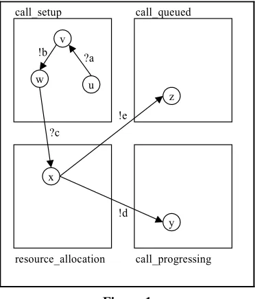
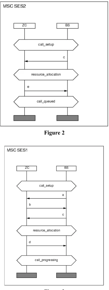
The DFSA of Figure 1 is a minimal automaton which is defined by the phase semantics for instance ZC of the MSC-s of Figure 2 and Figure 3. The boxes delimit the phases in the automaton. For a message m in an MSC the diagram uses !m to denote the send event for m, and ?m to denote the receive event for m. Each circle is a state of the automaton and an arrow between two states is a transition. An arrow label is the event associated with the transition. Interestingly the phase semantics have forced the automaton to be capable of both a !d and !e transition in state x. That is the implementation is able to non-deterministically choose between two send events in state x.
If instance ZC is meant to be a system component, such as a zone controller, it should not be capable of making a non-deterministic choice between different send events. It should be the case that the current state contains all relevant data to uniquely determine what the next send event is from the given inputs. In this case the single input ?c allows ZC to arbitrarily choose to either queue a call or progress it. In this hypothetical case this could lead to a situation where the ZC can arbitrarily decide that all calls are queued and no call ever completes. This example represents a conflict between the two use cases, and is clearly quite significant.
[image:3.595.205.391.505.723.2]This illustrates that a DFSA implementation given by the phase semantics can describe conflicts that are implicit in the specification but not explicit.
Figure 2
Figure 3
Any DFSA which partitions the states of the automaton into phases, corresponding to the phases of operation in the specification, is a phase automaton. In the next section we describe how to construct this automaton.
Method for defining the Phase Automaton.
The input to the method is the collection of phase traces from the specification of one of the components in the specification. Where the specification is a collection of MSC-s we assume that each instance represents a system component. The output to the method is a phase automaton which is an implementation of this set of phase traces. For example consider the MSC-s in Figure 2 and Figure 3. For brevity denote call_setup by CS, resource_allocation by RS, call_progressing by CP, and call_queued by CQ. We can write the ZC phase traces in this form:
t1 = CS, ?a, CS, !b, CS, ?c, RS, !d, CP (phase trace from MSC SES1) t2 = CS, ?c, RS, !e, CQ (phase trace from MSC SES2)
The phase semantics require that the states of any implementation is divided up into sets defined by the phases in the traces. In the example this means that the states are split up into four sets, one for the CS phase, one for the RS phase, one for the CP phase and one for the CQ phase.
Each phase trace forces certain states to exist in the automaton. Notice how the phase traces of the above example are lined up so that the initial section of the second trace matches the middle of the first trace. When this occurs we have an overlap. These overlaps provide a method of defining a minimal implementation for a set of phase traces. The implementation is defined to have a set of states for each phase in the specification. Initially no states are allocated to these sets. For each phase trace in turn define states and transitions in the automaton as follows. Suppose a phase trace is of the form
S0, e1, S1, e2, ..., Sn, en, S(n+1)
where the Si are phases and ei are events. For each triple Si, e(i+1), S(i+1) define states x(i) and x(i+1) in the automaton, with x(i) defined to be in the phase Si and x(i+1) is defined to be in the phase S(i+1). Further add a transition <x(i), ei, x(i+1)> to the automaton.
Once this is done for every phase trace we have an automaton which certainly generates all the phase traces for the instance specification, but is not yet an implementation as defined by the semantics of the previous section. For the above example such an initial automaton would be equivalent to Figure 4, where we have simplified the names of the states for convenience.
Figure 4
Next we introduce states to ensure every precursor to a phase trace can be extended to generate that phase trace. Recall that every precursor to a phase trace must be extendable to complete that phase trace. When a precursor matches two phase traces, which are the cause of a trace overlap, we merge some of the states which reduces the overall state space.
In the example states w and w’ belong to precursors. The sequence <u, ?a, v>, <v, !b, w> is a precursor to phase trace t1. State w’ is an exit state for phase call_setup and forms the empty precursor to phase t2. Hence state w is also a precursor to t2. That means for the automaton to be an implementation it must be possible to complete phase trace t2 from w. This can be done by adding a state z in phase call_queued and a transition <x, !e, z>.
The state space is now reduced as follows. Merge states z and z’ into a single state z, merge x and x’ into a single state x and states w and w’ into a single state w. This gives the implementation of Figure 1. This is valid as we are simply removing redundant states from the automaton.
In general we compare any precursors that are derived from an overlap of phase traces. The exit states that are the ends of the precursors, are merged into a single state. Any successors states are then recursively merged to ensure the automaton is deterministic. In the example states w and w’ are the exit states which are merged. Then to ensure nondeterminism x and x’ are merged, and then z and z’ are also merged for this reason.
Finally the state space can be minimised using any standard automata minimisation algorithm. The result is a phase automaton which implements the given set of phase traces. This is the minimal such automaton, that is one with the fewest states. As described in the example this can be analysed for possible feature conflicts.
Novelty