Constant Modulus Algorithm Aided Soft Decision-Directed Blind Space-Time Equalization for
SIMO Channels
S. Chen, A. Wolfgang and L. Hanzo
School of Electronics and Computer Science University of Southampton, Southampton SO17 1BJ, U.K.
ABSTRACT
Smart antenna aided broadband beamforming plays an increas-ingly important role in wireless communications. The paper inves-tigates blind space-time equalization/equalizers (STE) designed for single-input multi-output (SIMO) systems. Specifically, the con-stant modulus algorithm (CMA) and a soft decision-directed (SDD) scheme, originally derived for low-complexity blind equalization of single-input single-output (SISO) channels, are combined for em-ployment in the SIMO scenario.
I. INTRODUCTION
Space-time processing techniques have increasingly been applied to wireless communication systems [1]-[6]. With the aid of smart antenna arrays and by exploiting both the space and time dimen-sions, space-time processing is capable of effectively improving the system’s capacity, coverage and quality by suppressing intersymbol interference and reducing co-channel interference. In this paper, we investigate a blind STE designed for the SIMO channel by employ-ing a transmitter usemploy-ing a semploy-ingle antenna and a receiver employemploy-ing multiple antennas. We extend the combined CMA SDD scheme, originally derived for SISO systems [7], for employment in SIMO system. Simulations are conducted to compare the performance of this blind adaptive scheme to that of a CMA and decision directed (DD) scheme, which was originally derived also for the SISO sys-tem [8].
II. SYSTEMMODEL
Consider the SIMO system employingLreceiver antennas, as de-picted in Fig. 1, wheres(t)is the transmitted signal,xl(t)denotes
thelth antenna’s output signal andel(t)thelth channel’s noise. The
received signals are sampled at a rate of twice the symbol ratefsto
obtainx¯l(n),1 ≤l ≤ L, which are passed to the STE shown in
Fig. 2. Since the sampling rate is twicefs, the delay unit∆used in
the temporal filters equalsTs/2, whereTsis the symbol period. For
Σ
Σ
Σ
e (t)
e (t) 1
2
L x (t)1
x (t)L 2 x (t) e (t)
...
Transmitter s(t)
[image:1.595.310.541.473.684.2]...
ReceiverFig. 1. Single-input multiple-output system employing multiple receiver antennas.
notational convenience, the indexkis reserved forTs-spaced
sam-pled quantities and the indexnforTs/2-spaced sampled quantities
throughout our discussions. The transmittedTs-spaced
complex-valued symbol sequences(k) =sR(k) +jsI(k)is assumed to be
i.i.d. and the symbol constellation isM-QAM with the set of all the phasor points defined by
S={si,l= (2i−Q−1) +j(2l−Q−1), 1≤i, l≤Q}, (1)
where we haveQ=√M andj=√−1. TheTs/2-spaced signal
samplesx¯l(n)of thelth antenna are given by
¯
xl(n) =
2Nc−1
i=0
¯
ai,l¯s(n−i) + ¯el(n), (2)
where theTs/2-spaced sequence{s¯(n)}is a zero-padded version
of the transmitted symbol sequence {s(k)} defined by s¯(n) = s(n/2) for even n and ¯s(n) = 0for odd n. Furthermore the Ts/2-spaced complex-valued Channel Impulse Response (CIR) of
thelth channel is given by¯al= [¯a0,la¯1,l¯a2,l¯a3,l· · ·¯a2Nc−1,l]T,
with Nc corresponding to the Ts-spaced lth CIR duration, and
theTs/2-spaced noise sample¯el(n) = ¯el,R(n) +je¯l,I(n)is an
i.i.d. complex-valued Gaussian white noise process associated with E[¯e2l,R(n)] =E[¯e2l,I(n)] =σ2e.
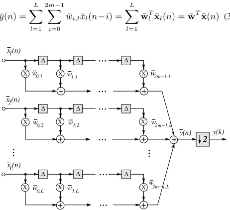
The STE consists ofLnumber ofTs/2-spaced temporal filters,
and its output is defined by
¯
y(n) = L
l=1
2m−1
i=0 ¯
wi,l¯xl(n−i) = L
l=1 ¯ wT
lx¯l(n) = ¯wTx¯(n) (3)
X X
X
...
...
...
++ +
X
...
+
...
...
+
+
X X
...
...
x (n)
x (n)L
1
∆ ∆ ∆
∆ ∆
∆
∆ ∆ ∆
w
X X
0,1 w w2m−1,1
w0,2 w1,2 w2m−1,2
w w w2m−1,L
0,L 1,L
+
X
2
x (n)
[image:1.595.85.257.594.701.2]2 y(k) y(n) 1,1
Fig. 2. Space-time equalization structure using∆-spaced temporal filters, where∆ =
where2mis the order of theTs/2-spaced temporal filters,w¯ = [ ¯wT
1 w¯T2 · · ·w¯LT]T and¯x(n) = [¯x1T(n) ¯xT2(n)· · ·x¯TL(n)]T, with ¯
wl = [ ¯w0,l w¯1,l· · ·w¯2m−1,l]T and ¯xl(n) = [¯xl(n) ¯xl(n − 1)· · ·x¯l(n−2m+ 1)]T being the complex-valued weight
vec-tor and input vecvec-tor of the lth temporal filter, respectively. The Ts/2-spaced output¯y(n)is decimated by a factor of2to create
theTs-spaced outputy(k). Following the same approach for the
SISO fractionally spaced equalizer [9], theTs-spaced model ofy(k)
can be derived, which can be used for developing adaptive algo-rithms. Let us first define the even and odd channels ofa¯las¯ael = [¯a0,l a¯2,l· · ·¯a2Nc−2,l]T and ¯aol = [¯a1,l¯a3,l· · ·a¯2Nc−1,l]T, the
even and odd equalizers ofw¯lasw¯el = [ ¯w0,lw¯2,l· · ·w¯2m−2,l]T
andw¯lo = [ ¯w1,lw¯3,l· · ·w¯2m−1,l]T, the even and odd noise
sam-ples aseel(k) = ¯el(2n)andeol(k) = ¯el(2n+ 1), and the even and
odd samples ofxl(n)asxel(k) = ¯xl(2n)andxol(k) = ¯xl(2n+ 1).
Furthermore we define
wl= [w0,lw1,l· · ·w2m−1,l]T =
( ¯wo
l)T ( ¯wel)T T
(4)
and
xl(k) = [xl(k)xl(k−1)· · ·xl(k−2m+ 1)]T
=(xe
l(k))T(xol(k))T T
(5)
withxel(k) = [xel(k)xel(k−1)· · ·xel(k−m+ 1)]Tandxo l(k) = [xo
l(k)xol(k−1)· · ·xol(k−m+ 1)]T. Then theTs-spaced STE
outputy(k)is given by
y(k) = L
l=1 2m−1
i=0
wi,lxl(k−i) = L
l=1
wT
lxl(k) =wTx(k) (6)
withw = [wT1 · · ·wTL]T andx(k) = [xT1(k)· · ·xTL(k)]T. The overall signal to noise ratio (SNR) of the system is defined as
SNR= σ
2
s L
l=1
2Nc−1
i=0 |a¯i,l|2
4Lσ2e , (7)
whereσs2 =E[|s(k)|2]. We will extend an initialization strategy
commonly used for SISO blind equalization [9] to the present blind STE. Before blind adaptation, the equalizer weights are initialized tow¯i,l=L1 +j0fori=m−1andm, andw¯i,l= 0 +j0for all
the other values ofi, where1≤l≤L.
III. CMA AIDEDSOFTDECISIONDIRECTEDSCHEME
Let each temporal filter of the STE be split into two parts, namely
wl =wcl+wdl, and denotew =wc+wd. The weight vector
wc of the CMA STE is designed for minimizing the CMA’s cost
function
¯
JCMA(w) =E|y(k)|2−R22
(8)
by adaptingwcusing a stochastic gradient algorithm, whereR2 =
E|s(k)|4/E|s(k)|2. Similar to the case of SISO blind equal-ization [10][11], at the Ts-spaced sample k and given y(k) =
wT(k)x(k), the CMA adaptsw
caccording to
(k) =y(k)R2− |y(k)|2
wc(k+ 1) =wc(k) +µCMA(k)x∗(k)
, (9)
whereµCMAis a small positive adaptive gain factor andx∗(k)is the complex conjugate ofx(k). Typically, a small adaptive gain µCMAhas to be used for ensuring convergence.
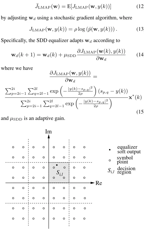
Let the complex plane be divided intoM/4rectangular regions, as illustrated in Fig. 3. Each regionSi,lcontains four symbol points
Si,l={sp,q, p= 2i−1,2i, q= 2l−1,2l}. (10)
If the equalizer outputy(k)is within the regionSi,l, a local
ap-proximation to thea posterioriprobability density function (p.d.f.) ofy(k)is [13]
ˆ
p(w, y(k))≈ 2i
p=2i−1 2l
q=2l−1
1 8πρexp
−|y(k)−sp,q|2 2ρ
,
(11) whereρis the “variance” or width of the clusters. This approxima-tion is only valid however when the equalizer has converged. Before reaching this stage, a bootstrap optimization process can be per-formed for arriving at the MAP solution, as presented in [12],[13]. The subsequently activated SDD equalizer was designed for maxi-mizing the log of the locala posteriorip.d.f. criterion was
¯
JLMAP(w) =E[JLMAP(w, y(k))] (12)
by adjustingwdusing a stochastic gradient algorithm, where
JLMAP(w, y(k)) =ρlog (ˆp(w, y(k))). (13)
Specifically, the SDD equalizer adaptswdaccording to
wd(k+ 1) =wd(k) +µSDD∂JLMAP
(w(k), y(k))
∂wd
(14)
where we have
∂JLMAP(w, y(k))
∂wd
= 2i
p=2i−1 2l
q=2l−1exp
−|y(k)−sp,q|2
2ρ
(sp,q−y(k)) 2i
p=2i−1
2l
q=2l−1exp
−|y(k)−sp,q|2
2ρ
x∗(k)
(15) andµSDDis an adaptive gain.
Im
Re i,l
S Si,l
soft output equalizer
[image:2.595.303.543.312.701.2]decision region point symbol
TABLE I
Comparison of the computational complexity per weight update. The number of receiver antennas isLand the order of temporal filters is2m. equalizer multiplications additions exp(•)
CMA 8×(L×2m) + 6 8×(L×2m) −
CMA+DD 16×(L×2m) + 8 20×(L×2m) − CMA+SDD 12×(L×2m) + 29 14×(L×2m) + 21 4
The complexity of the CMA aided SDD scheme is characterized in Table I. The fourexp(•)evaluations can be implemented using a look-up table in practice. The CMA aided DD scheme [8] can also be extended to the blind STE considered. The complexity of the CMA assisted DD blind STE as well as that of the pure CMA scheme was also listed in Table I.
IV. SIMULATIONSTUDY
Time-invariant system. Two performance criteria were used for
assessing the convergence rate of a blind STE. The first one was the decision-based estimated MSE calculated for each adaptation sam-ple based on a block ofNMSEnumber ofTs-spaced data samples,
yielding
MSE= 1 NMSE
NMSE
k=1
|Q[y(k)]−y(k)|2, (16)
whereQ[•]denotes the quantization operator. The second one was the maximum distortion (MD) measure defined as
MD = Nf−1
i=0 |fi| − |fimax|
|fimax| ,
(17)
wheref = [f0f1· · ·fNc−1]T was the combined impulse response of theLchannels and the STE defined by
f=
L
l=1
¯ wo
la¯el+ ¯wel¯aol, (18)
withdenoting convolution andNf =Nc+m−1being the length
of theTs-spaced combined impulse response, and in (17) we have fimax= max{fi,0≤i≤Nf−1}. The equalizer’s output phaser
after convergence was also shown in Fig 5 usingNtest= 6000Ts
-spaced testing data samples not used during the adaptation stage.
In our simulations, L = 4receiver antennas were employed and 256-QAM was used. TheL = 4Ts/2-spaced channels were
listed in Table II. The simulated CIRs were normalized accord-ing toa¯l/¯alfor1 ≤ l ≤ 4 to ensure that each channel had
a unit energy. The noise variance was σe2 = 0.00425, yielding
a SNR of 40 dB. The length of theTs/2-spaced temporal filters
was2m = 10. The learning curves of the two blind STEs, the
TABLE II
Ts/2-spaced CIRs used in the simulated time-invariant SIMO system.
l ¯al
1 -0.2+j0.3 -0.5+j0.4 0.7-j0.6 0.2+j0.1 2 0.3+j0.2 0.7-j0.5 -0.5+j0.4 0.4+j0.3 3 -0.1-j0.2 0.6+j0.4 -0.4+j0.3 0.1+j0.3 4 0.6+j0.7 0.5 +j0.4 -0.1-j0.2 0.2+j0.1
0 0.1 0.2 0.3 0.4 0.5 0.6
0 4000 8000 12000 16000
MSE
Sample CMA+DD CMA+SDD
(a)
0 0.1 0.2 0.3 0.4 0.5
0 4000 8000 12000 16000
MD measure
Sample CMA+DD CMA+SDD
(b)
Fig. 4. Comparison of the convergence performance of the CMA+DD and CMA+SDD schemes in terms of (a) estimated MSE and (b) MD measure for the time-invariant CIR of Table II.
CMA+DD and CMA+SDD, in terms of the estimated MSE and MD measure, are depicted in Fig. 4 (a) and (b), respectively, while the equalizer’s output signal constellations after convergence are illus-trated in Fig. 5. It can be seen that both the CMA+DD and the CMA+SDD blind STEs had a similar steady-state equalization per-formance, but the latter had a significantly faster convergence.
Fading system. Again,L = 4receiver antennas were used, but
64-QAM was used at a symbol rate of 4 MBaud. The baseband continuous-time system was simulated. The transmission pulse had a raised-cosine characteristics with a roll-off factor 0.5 and a square-root Nyquist characteristic at both the transmitter and receiver. The fading channels were implemented using the following tap-delay line models for1≤l≤4
vl(t) =c0,l(t)u(t) +c1,l(t)u(t−τ1) +c2,l(t)u(t−τ2) (19)
whereu(t)was the transmitter output and vl(t)was the lth
fad-ing channel output;τ1 ≈ 0.44Ts andτ2 ≈ 1.13Ts; the
magni-tudes of the complex-valued tap weightsci,l(t),0≤i≤2, were
i.i.d. Rayleigh processes and the root mean square (RMS) powers ofci,l(t)were[0.7 +j0.7 0.6 +j0.6 0.5 +j0.5], for0≤i≤2,
single transmit antenna to 4 receive antennas was represented by
R=
1 α β γ
α∗ 1 α β
β∗ α∗ 1 α γ∗ β∗ α∗ 1
(20)
with α = 0.97 exp(−j0.8), β = 0.94 exp(−j1.6) and γ =
0.88 exp(−j2.4) [14]. LetR = QΣQH, whereQconsists of the eigenvectors associated withRandΣis diagonal whose diag-onal elements are the eigenvalues ofR. Then the receiver antenna outputs are represented by
x1(t)
x2(t)
x3(t)
x4(t)
=QΣ1/2
v1(t)
v2(t)
v3(t)
v4(t)
+
e1(t)
e2(t)
e3(t)
e4(t)
. (21)
The receiver outputs were sampled at the rate of twice the symbol rate and passed to a STE whoseTs/2-spaced temporal filters had
[image:4.595.325.515.69.468.2]an order of 10.
Fig. 6 depicts the CMA+DD STE’s output signal constellations after (a) adaptation using 4000 symbols and (b) adaptation using 6000 symbols. Each signal constellation was shown for 6000Ts
-spaced samples invoking continuous adaptation, since the channels were time-varying. Similarly, Fig. 7 shows the CMA+SDD STE’s output signal constellations after (a) adaptation using 2500 symbols and (c) adaptation using 4500 symbols. It is readily seen that the CMA+SDD scheme had a significantly faster convergence rate than the CMA+DD arrangement.
V. CONCLUSIONS
In this paper, a novel low-complexity blind STE has been pro-posed for the SIMO system invoked by employing multiple receiver antennas, based on operating a CMA equalizer and a SDD equalizer concurrently. Simulation results have demonstrated that this blind STE performs well.
REFERENCES
[1] J.S. Blogh, L. Hanzo: Third-Generation Systems and Intelligent Wireless Net-working - Smart Antennas and Adaptive Modulation, John Wiley, April 2002, ISBN 0-470-84519-8430 pages.
[2] L. Hanzo, T.H. Liew, B.L. Yeap: Turbo Coding, Turbo Equalisation and Space-Time Coding, John Wiley, August 2002, ISBN 0-470-84726-3,766 pages. [3] L. Hanzo, M. M¨unster, B.J. Choi and T. Keller: OFDM and MC-CDMA for
Broadband Multi-user Communications, WLANs and Broadcasting, John Wiley - IEEE Press, July 2003,980 pages.
[4] L. Hanzo, L-L. Yang, E-L. Kuan and K. Yen: Single- and Multi-Carrier DS-CDMA: Multi-User Detection, Space-Time Spreading, Synchronisation, Stan-dards and Networking, IEEE Press - John Wiley, August 2003,1060 pages. [5] A.J. Paulraj and B.C. Ng, “Space-time modems for wireless personal
communi-cations,”IEEE Personal Communications, Vol.5, No.1, pp.36–48, 1998. [6] A. Paulraj, R. Nabar and D. Gore,Introduction to Space-Time Wireless
Commu-nications. Cambridge: Cambridge University Press, 2003.
[7] S. Chen, “Low complexity concurrent constant modulus algorithm and soft deci-sion directed scheme for blind equalisation,”IEE Proc. Vision, Image and Signal Processing, Vol.150, No.5, pp.312–320, 2003.
[8] F.C.C. De Castro, M.C.F. De Castro and D.S. Arantes, “Concurrent blind decon-volution for channel equalization,” inProc. ICC’2001(Helsinki, Finland), June 11-15, 2001, Vol.2, pp.366–371.
[9] R. Johnson, Jr., P. Schniter, T.J. Endres, J.D. Behm, D.R. Brown and R.A. Casas, “Blind equalization using the constant modulus criterion: a review,”Proc. IEEE, Vol.86, No.10, pp.1927–1950, 1998.
-20 -15 -10 -5 0 5 10 15 20
-20 -15 -10 -5 0 5 10 15 20
Im
Re (a)
-20 -15 -10 -5 0 5 10 15 20
-20 -15 -10 -5 0 5 10 15 20
Im
[image:4.595.69.289.200.244.2]Re (b)
Fig. 5. Equalizer output signal constellations after convergence (a) the CMA+DD, and (b) CMA+SDD for the time-invariant CIR if Table II.
[10] D. Godard, “Self-recovering equalization and carrier tracking in two-dimensional data communication systems,” IEEE Trans. Communications, Vol.COM-28, pp.1867–1875, 1980.
[11] J.R. Treichler and B.G. Agee, “A new approach to multipath correction of con-stant modulus signals,”IEEE Trans. Acoustics, Speech and Signal Processing, Vol.ASSP-31, No.2, pp.459–472, 1983.
[12] S. Chen, S. McLaughlin, P.M. Grant and B. Mulgrew, “Reduced-complexity multi-stage blind clustering equaliser,” inProc. ICC’93(Geneva, Switzerland), 1993, Vol.2, pp.1149–1153.
[13] S. Chen, S. McLaughlin, P.M. Grant and B. Mulgrew, “Multi-stage blind cluster-ing equaliser,”IEEE Trans. Communications, Vol.43, No.3, pp.701–705, 1995. [14] 3GPP, “Tx diversity solutions for multiple antennas,” 3GPP TSG RAN WG1
-10 -8 -6 -4 -2 0 2 4 6 8 10
-10 -8 -6 -4 -2 0 2 4 6 8 10
Im
Re (a)
-10 -8 -6 -4 -2 0 2 4 6 8 10
-10 -8 -6 -4 -2 0 2 4 6 8 10
Im
[image:5.595.330.515.177.571.2]Re (b)
Fig. 6. CMA+DD equalizer output signal constellations for the fading system: (a) after adaptation of 4000 symbols and (b) after adaptation of 6000 symbols. 6000
Ts-spaced samples were used in showing the signal constellation with continuous adaptation.
-10 -8 -6 -4 -2 0 2 4 6 8 10
-10 -8 -6 -4 -2 0 2 4 6 8 10
Im
Re (a)
-10 -8 -6 -4 -2 0 2 4 6 8 10
-10 -8 -6 -4 -2 0 2 4 6 8 10
Im
Re (b)
Fig. 7. CMA+SDD equalizer output signal constellations for the fading system: (a) after adaptation of 2500 symbols and (a) after adaptation of 4500 symbols. 6000
[image:5.595.75.260.177.569.2]