This is a repository copy of
Tuneable and switchable liquid crystal laser protection system
.
White Rose Research Online URL for this paper:
http://eprints.whiterose.ac.uk/121787/
Version: Accepted Version
Article:
Jull, EI and Gleeson, HF orcid.org/0000-0002-7494-2100 (2017) Tuneable and switchable
liquid crystal laser protection system. Applied Optics, 56 (29). pp. 8061-8066. ISSN
1559-128X
https://doi.org/10.1364/AO.56.008061
© 2017 Optical Society of America. This is an author produced version of a paper
published in Applied Optics. Uploaded in accordance with the publisher's self-archiving
policy.
[email protected]
https://eprints.whiterose.ac.uk/
Reuse
Items deposited in White Rose Research Online are protected by copyright, with all rights reserved unless
indicated otherwise. They may be downloaded and/or printed for private study, or other acts as permitted by
national copyright laws. The publisher or other rights holders may allow further reproduction and re-use of
the full text version. This is indicated by the licence information on the White Rose Research Online record
for the item.
Takedown
If you consider content in White Rose Research Online to be in breach of UK law, please notify us by
!
uneable and switchable liquid crystal laser
protection system
E
THAN
I.
L.
J
ULL
*
AND
H
ELEN
F.
G
LEESON
School of Physics and Astronomy, University of Leeds, Leeds, LS2 9JT, England *Corresponding author: [email protected]
The use of a liquid crystal Lyot filter as a simple and compact switchable laser protection system is demonstrated. The system OFF state exhibits a wavelength-independent transmission and switches to an ON state, which rejects a selected wavelength. The response time of the switchable system is <110 ms, depending on the rejected wavelength, with the ability for faster switching of <5 ms when using a lower-order rejection band. A rejection tuning range between 480 and 640 nm is demonstrated, and the potential to operate outside of the visible spectrum is discussed. In the ON state, the transmission at the rejected wavelength was found to be effectively limited by the polarizer extinction ratio, while transmission at other wavelengths allows for partial observations through the system even when in protection mode.
1. Introduction
High-powered handheld laser with high intensity and coherent radiation can dazzle and cause permanent damage to sensor and surveillance systems. Such devices are becoming increasingly easy to acquire; therefore, there is an urgent demand for protective systems. Successful systems need to effectively reject specific laser wavelengths, thus providing much needed protection while permitting continuous operation.
Tuneable liquid crystal Lyot filters can select a specific wavelength by applying a wavelength-dependent retardance to light passing through aligned polarizers. Lyot filters were first developed in 1933 by Lyot [1], and their initial implementation into astronomical
observations was widespread [2]. It was not until 1990 that a liquid crystal component was implemented as the birefringent material. This was first achieved by Miller [3] in 1990, allowing radiometric and photometric standards to be linked. The ability to directly control the transmission spectrum through application of an electric or magnetic field to the liquid crystal element led to many further developments and applications of the Lyot filter to astronomical spectral observations [4-8], remote sensing [9, 10], laser tuning [11], and biological imaging [12, 13]. In recent years, the focus has shifted toward the optimization of the transmission spectrum for specific applications. These
optimizations include increasing the tunability [14], free spectral range [15]. Switching speed [16], contrast ratio [17], and spectral resolution [16] and also reducing the passband size [14] or the appearance of side lobes [18].
The designs use a variety of arrangements, occasionally including multiple Lyot filter stages, creating narrow transmission windows, and ideally removing transmission at all other wavelengths. However, in the application described in this paper, the opposite effect is required
to achieve protection of devices from laser radiation. Thus, our design focuses on sufficient extinction at a specific (laser) wavelength while retaining as much transmission as possible at other wavelengths. This means that protection from the laser radiation is achieved, while partial observations are still possible using other wavelengths while the sensor is “under threat”.
For a laser protection system to be effectively implemented it must be possible to switch from a full wavelength-independent transmission mode, with transmission across the entire visible spectrum, to a specific wavelength rejection mode. Thus, the sensor or camera can operate without compromise when it is not “under threat” by laser radiation. However, when “under threat,” the system will switch to reject the specific laser wavelength, while allowing continued sensor operation via the partial transmission at other wavelengths. The ability for the protection system to be tuned to reject a range of wavelengths is also important, as many different lasers may be used by a potential attacker. The system should also have: a fast response time, to minimize the laser power incident on the sensor; a compact design, to avoid unnecessary optical compromises; and ideally, low operating voltages and power consumption.
There are few reports of tuneable liquid crystal Lyot filters being implemented in sensor protection against laser radiation [19, 20]. Although the designs implemented by Rees and Staromlynska [19] and Wu and Wu [20] performed well for the applications considered, they were unable to demonstrate switching between a full transmission and a dependent rejection mode. The
wavelength-independent transmission mode is, however, quite clearly realized when a voltage much higher than threshold is applied to a liquid crystal device. Further, in one case the response time of the liquid crystal Lyot filter was not quantified [19]; in the other, the design was bulky and used a prism [20].
In this paper, we clearly describe the design and evaluation of a simple, compact, tuneable liquid crystal Lyot filter for laser protection. We demonstrate switching from a wavelength-independent transmission mode, allowing operation across the entire visible spectrum, to a rejection mode at a chosen specific wavelength. The ability to tune to a specific wavelength rejection is important for protection against the wide variety of powerful handheld lasers now available. Importantly, the response times for switching between various rejection states are experimentally evaluated and shown to be sufficiently fast to allow protection against laser attack. Thus, although Lyot filters are well-known, we demonstrate a combination of desirable features that would allow them to be used in a new, increasingly important application.
A Liquid Crystal Lyot Filter
A single-stage liquid crystal Lyot filter is comprised of a liquid crystal variable retarder sandwiched between two linear polarizers, as depicted in Fig. 1(a). The linear polarizers are uncrossed, and the liquid crystal device is oriented for maximum retardance. The liquid crystal device has a cell gap d and a voltage-dependent effective birefringence
Δn(V), resulting in a retardance of Γ=2πΔn(V)d/λ, where λ is the wavelength of light [15]. Wavelengths that satisfy the half-wave-plate condition (λ=dΔn/(m-½), m is an integer) will be blocked by the analyzer and are thus rejected; this effect is utilized for laser protection. The parameters d and Δn can be initially varied over ranges of typically 2-20 µm and 0.05 to 0.25, respectively, allowing initial calibration of the rejection wavelength. In this paper, we select a cell gap of ~5 µm and the liquid crystal 4-pentyl-4’-cyanobiphenyl (5CB) with a birefringence of ~0.2, giving an initial rejection band at ~667 nm for
m=2. The voltage-dependency of the effective birefringence “observed” by plane polarized light allows tunability, as discussed later in the paper.
The percentage transmission, T, is given by Eq. (1) [15]:
! !cos! !!! !cos! !!! ! !!! , (1)
where polarizer and Fresnel losses (~55% for unpolarised light) have been neglected.
The wavelength-dependence of the birefringence has been considered via the extended Cauchy model [21], which is used to determine the birefringence dispersion for 5CB at a temperature of 25.1 °C. This allows for accurate modeling of the transmission spectrum.
B. Liquid Crystals
The use of liquid crystals in displays and other electro-optic devices is well known, and the Lyot filter application makes use of liquid crystal properties [22]. In the liquid crystal device, a nematic liquid crystal with positive dielectric anisotropy is contained in a planar-aligned geometry such that the average molecular direction (the director,!)
lies in a single direction parallel to the glass plates of the cell.
Application of a voltage causes reorientation of the director toward the field lines (perpendicular to the glass plates) and hence a reduction in the effective birefringence of the device, an example of which is shown in Fig. 1(b). This is a continuous process above a material-dependent threshold voltage, Vth, giving the direct control over the retardance of the device and hence the transmission spectrum.
The switching speed of the liquid crystal device is governed by the initial state, magnitude of the applied field, and the elastic restoring forces. Equation (2) describes the rise time for the director to reorient in response to an applied voltage, V > Vth. Equation (3) describes the fall time associated with changing the applied voltage to a lower value, Vb. The majority of liquid crystal devices operate such that the applied voltage is completely removed, Vb=0. However, in this device operation
is more complex and a bias voltage is needed to switch to laser protection mode.
!!∀#∃! !!!!!!!!!!!! !
!!!!! (2)
!!∀##! !!!! !!!!!!!! !!!!! ! (3)
where η is the rotation viscosity, Δε is the dielectric anisotropy, and
k11is the splay elastic constant [23].
Fig. 1. (a) Schematic of a liquid crystal Lyot filter is shown. The polarizer and analyzer, in the xy plane, are at 45° to the x axis, while the liquid crystal director is aligned with the x axis. Image redrawn from Yang et al. [18] (b) Voltage dependency of birefringence for 5CB has been theoretically calculated to demonstrate the ability to tune the bulk birefringence.
2. Experimental Methods
The liquid crystal device was made from two pieces of glass, coated with indium tin oxide electrodes. A liquid crystal alignment layer of 0.5% poly(vinyl alcohol) solution in water was spin-coated onto the glass substrate and rubbed for unidirectional alignment. UV glue mixed with 5 µm spacer beads was used to construct a cell, with the cell gap of the device measured to be (6.0 ± 0.2) µm using reflection spectroscopy [24].
Transmission spectra of the Lyot filter were measured, between 400 and 800 nm, using a modified Olympus BH-2 microscope coupled to an Ocean Optics HR4000 high-resolution spectrometer, which is described in detail elsewhere [24]. The transmission was normalized with respect to the experimental losses, as described later. While the spectra were measured, the liquid crystal device was held at a constant temperature of (24.0 ± 0.1) °C using a Linkam THMS600 hot stage and Linkam TMS91 controller.
For switching and tuning sinusoidal voltages up to ~30 Vrms, at a
generators coupled with a high-voltage wideband amplifier. This configuration allows switching between specific rejection wavelengths; the first waveform generator applied the starting voltage and then triggers the application of the second voltage, providing a fast, smooth transition between voltages. The intensity was measured using a photodiode, and the 10%-90% intensity values were measured. The time between these two points was taken as the response time, which was measured for specific wavelengths by coupling a lower power laser diode (λ = 532 nm) into a polarizing microscope.
The use of polarizers in this type of filter inherently reduces the light transmission by approximately 50%. Fresnel reflections at the glass air interfaces result in a further ~8% loss, leading to a maximum theoretical transmission of ~42%. The experimental normalization procedure removes the polarizer losses only (50%). Therefore, 100% transmission in the data corresponds to 50% transmission when the filter is implemented. The Fresnel losses, material absorptions, or any other optical losses are not accounted for in normalization and therefore will appear in the data.
Fig. 2. (a) Theoretical [Eq. (1)] and experimental Lyot filter transmission as a function of wavelength. (b) Transmission spectra for a single-stage liquid crystal Lyot filter for the OFF state (30 Vrms applied) with uniform transmission across the visible spectrum and the ON state (0 Vrms applied),
which rejects 650 nm light. Images taken in each state using a Nikon D7100 camera demonstrate the ability for partial observations when in protection mode. (c) Transmission spectra of a single-stage 5CB Lyot filter as a function of applied voltage. The rejection wavelength shifts toward the blue end of the spectrum with increasing voltage. (d) Rejected wavelength is found to approximately vary linearly with applied voltage. The original data associated with this work are available from the Research Data Leeds repository under a CC-BY license at http://doi.org/10.5518/222.
3. Results and Discussion
The transmission of the liquid crystal Lyot filter measured I the absence of a field is shown in Fig. 2(a), where experimental data and the theoretical calculations [Eq. (1)] are seen to be in excellent agreement. The spectrum in Fig. 2(a) is defined as the ON state, with the liquid crystal device exhibiting maximum birefringence and rejecting a specific wavelength (655 nm), with less than 1.0% transmission between 648 and 665 nm. For a class 4 red laser (500 mW), the incident power would be reduced to approximately 5 mW, corresponding to a class 3R low risk laser. In practice, this minimum in transmission is limited by the extinction ratio of the
polarizers. If the polarizers were ideal, then the resultant transmission would approach the theoretical minimum of zero. Fabry-Perot interference fringes are also observed in all transmission spectra, as can be seen from the small, wavelength-dependent fluctuations. These fringes are a result of the interference that occurs when the light is reflected between two plane parallel plates.
On application of a voltage of 30 Vrms, Fig. 2(b), the birefringence of
[image:4.612.69.542.165.513.2]ability to switch the system from maximum transmission at all wavelengths, standard operation, to rejection of specific wavelengths, protection mode. The relatively high voltage required for full transmission would not impede the application of this system for sensor or camera protection as the power requirements of liquid crystal devices are extremely low. It can also be seen in Fig. 2(b) that the operation of a camera, while in protection mode, is still possible.
Tunability is achieved over a wide spectral range by varying the applied voltage and hence the effective birefringence. Figure 2© shows the effect of changing the voltage between 0.67 and 1.06 Vrms. As the
voltage is increased the transmission spectrum blueshifts. The minimum transmission wavelength (corresponding to the half-wave condition) was determined as a function of voltage, and the relationship is shown in Fig. 2(d) to be approximately linear. The rejection wavelength has a wide tuneable range spanning the visible spectrum, i.e. from 475 to 650 nm. Indeed, in principle, a much larger wavelength range can be accessed if the higher-order half-wave-plate conditions were utilized (increasing the integer value m), provided that any absorption bands associated with the liquid crystal material and substrates are avoided.
Equation (4) gives the fitted linear function, applicable for the demonstrated voltage range, which can be used as a calibration for this specific protection system. For instance, given that a specific
wavelength laser (λ = 532 nm) is dazzling a sensor the calibration equation can be sued to determine the voltage required to reject this wavelength. In this case, a voltage of (0.943 ± 0.003) Vrms would be
required to alter the birefringence such that a half-wave-plate condition is met:
!!∀#!��! !646! !∀#
!!!!!!∀!. (4)
By coupling the switching ability with this tuning, the system can be switched from the OFF state (~30 Vrms) to a specific ON state, with the
response time for this switch limited by the detection system and the response speed of the liquid crystal device (typically milliseconds). To test the response speeds of the filter itself, a green laser module (λ = 532 nm) was coupled to the system. The blocking voltage required for this laser wavelength is (0.943 ± 0.003) Vrms. A photodiode was used to
measure how the intensity varies with time when switching from the OFF to the ON state, as demonstrated in FIG. 3(a).
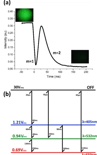
The response time of the system is clearly an important factor in its design for the rejection of laser wavelengths. Schwarz et al. [25] showed that the longer the exposure time the lower the laser power required to damage the sensor system. When the Lyot filter is sued to protect against the green laser, the intensity is reduced to (4.7 ± 0.1)% of the maximum intensity when the filter is switched from the transmission OFF state to the rejection ON state. The ON switching mechanism for the liquid crystal is a relaxation rather than being a driven response via increased voltage and is therefore predicted using literature values for 5CB [26-28], in Eq. (3), to be 59 ms. The switch speed was experimentally measured to be τON = (60 ± 10) ms, which compares extremely well with the predicted value. Switching back to the OFF state resulted in a rise time of τOFF = (45 ± 5) µs. The first minimum in intensity, seen in Fig. 3(a), corresponds to the lower order half-wave-plate condition (m = 1) passing through λ = 532 nm; in Figs. 2(a) and 2(b) the minima correspond to the second order condition (m = 2). In this case, the first-order minimum could potentially be sued to increase the switching speed of the device to approximately 5 ms; however, the first order condition has the disadvantage of a large full-width-half-maximum, meaning that partial observations are not as clear as in the second-order case.
The above test has demonstrated the validity of the calibration equation and how this system can be implemented as a laser protection element, with the ability to be applied to different
protection schemes. If faster switching is required, the lower-order minima can be utilized, but if partial observations are more important and the sensor is more resilient, a higher-order condition and therefore longer switch time can be used.
Fig. 3. (a) Change in intensity measured as a function of time for switching a single-stage Lyot filter from the OFF state (30 Vrms) to the
ON state for λ = 532 nm (0.940 Vrms). Change in intensity is clear, and
the response time is τON = (60 ± 10) ms. Data points were averaged using the adjacent-averaging method. Image inserts are of the laser spot in the far field, taken using a deltaPix camera. (b) Response times associated with switching between different protection schemes are shown. Error for values in the millisecond range is ± 10 ms; in the microsecond range, it is ± 5 µs.
To further test switching speeds between states, the three most currently accessible handheld laser wavelengths were taken as λ = 650 nm (red), λ = 532 nm (green), and λ = 405 nm (blue). From Eq. (4) blocking voltages of 0.69 Vrms (red), 0.94 Vrms (green), and 1.21 Vrms
(blue) were calculated. The switching times between all possible states are shown in Fig. 3(b).
In switching from the OFF state to a specific rejection state, response times of 40-110 ms were found. If switching between specific
wavelength blocking states, the response times range between 40 and 230 ms.
We can consider the effectiveness of our system in protecting sensor system from laser radiation by putting our results in context with existing literature, which evaluates damage to cameras caused by lasers. Schwarz et al. found it difficult to cause damage to a CCD camera with a continuous laser when the exposure time of the CCD camera to the laser was kept below 250 ms [25]. Specifically, no damage occurred below a power density of 159 kWcm-2. Assuming a beam diameter of 6
[image:5.612.339.535.101.413.2]the switching speeds of our filter, all faster than 110 ms, should provide excellent protection for a CCD camera against lasers with powers of ≤20 W.
4. Conclusion
A switchable, tuneable, liquid crystal Lyot filter was designed and tested as a laser protection system using both broadband and monochromatic light sources. A tuneable rejection range of 475-650 nm was experimentally demonstrated using low voltages from 0.6 to 1.05 Vrms. Theoretically the tuning range is much larger due to the
extended transmission spectrum of a Lyot filter, namely, the
higher/lower order half-wave-plate conditions. A calibration equation was extracted from the tuning data, allowing specific wavelength rejection voltages to be deduced. Switching between a full transmission mode and a selective wavelength rejection mode was demonstrated, using a broadband light source and a high-resolution spectrometer. This was achieved by switching the applied voltage to the liquid crystal cell from 30 to 0 Vrms, with a minimum in
transmission of 1.0% at the rejection wavelength. The system was tested using a laser source (λ = 532 nm) and was shown to switch between a transmission OFF state to an ON state in (60 ± 10) ms, using voltages of 30 and 0.94 Vrms, respectively.
The implementation of the Lyot filter as a protection system would be incredibly simple, with straightforward calibration tests allowing for any temperature dependence of the liquid crystal’s birefringence to be accounted for. Threshold voltage effects could potentially be avoided through the use of a copolymer network liquid crystal, which would allow for continuous tuning [29], although this may result in scattering effects. By coupling this laser filter with a warning system, the system can switch rapidly from full transmission to a blocking state, thus providing much needed protection from dazzling and permanent damage. The system shows promise as a compact, rapid, and tuneable laser protection device that could be implemented with ease in the protection of sensors or surveillance cameras.
Funding Information. Engineering and Physical Sciences Research
Council (EP/N509681/1)
References
1.Lyot, B. M. and Fabry, C. M. Un monochromateur a grand champ utilisant les interferences en lumiér polarisée. Comptes renduc de l’académie des sciences. 1933, 197, pp. 1593-1595
2.Lyot, B. M. Planetary and solar observations on the pic du midi in 1941, 1942, and 1943. Astrophysical Journal. 1945, 101(2), pp.896-901 3.Miller, P. J. Use of tunable liquid crystal filters to link radiometric and
photometric standards. Metrologia. 1991, 28, pp.145-149
4.November, L. J. and Wilkins, L. M. Liquid crystal polarimeter: a solid state imager for solar vector magnetic fields. Optical Engineering. 1995,
34(6), pp.1659-1668
5.Kopp, G. A., Derks, M. J., Elmore, D. F., Hassler, D. M., Woods, J. C., Streete, J. L., and Blankner, J. G. Tunable liquid-crystal filter for solar imaging at the He I 1083-nm line. Applied Optics. 1997, 36(1), pp.291-296
6.Cau, W., Jing, J., Ma, J., Xu, Y., Wang, H., and Goode, P. R. Diffraction-limited polarimetry from the infrared imaging magnetograph at big bear solar observatory. The Astronomical Society of the Pacific. 2006,
118(844), pp. 838-844
7.Elmore, D. F., Card, G. L., Chambellan, C. W., Hassler, D. M., Hull, H. L., Lecinski, A. R., MacQueen, R. M., Streander, K. V., Streete, J. L., and White, O. R. Chromospheric helium imaging photometer (an instrument for high time cadence 1083-nm wavelength solar observations). Applied Optics. 1998, 37(19), pp.4270-4276
8.Ichimoto, K., Noguchi, M., Tanaka, N., Kumagai, K., Shinoda, K., Nishino, T., Fukuda, T., and Sakurai, T. A new imaging system of the corona at norikura. Astronomical Society of Japan. 1999, 51(3), pp. 383-391 9.Rees, A. A. M., Staromlynska J., Gillyon, M. P., and Davy, J. R. Final design
and testing of the laser airborne depth sounder filter. Society of Photo-Optical Instrumentation Engineers. 1997, 36(4), pp.1204-1213 10.Seymour, R. S., Rees, S. M., Staromlynska, J., Richards, J., and Wilson, P.
Design considerations for a liquid crystal tuned Lyot filter for laser bathymetry. Optical Engineering. 1994, 33(3), pp.915-923 11.Gleeson, H. F., Murray, A. J., Fraser, E., and Zoro, A. An electrically
addressed liquid crystal filter for tunable lasers. Optics Communications. 2002, 212(1-3), pp.165-168
12.Morris, H. R., Hoyt, C. C., and Treado, P. J. Imaging spectrometers for fluorescence and raman microscopy: acouto-optic and liquid crystal tunable filters. Applied Spectroscopy. 1994, 48(7), pp.857-866 13.Morris, H. R., Hoyt, C. C., Miller, P., and Treado, P. J. Liquid crystal
tunable filter raman chemical imaging. Applied Spectroscopy. 1996,
50(6), pp.805-811
14.Staromlynska, J., Rees, S. M., and Gillyon, M. P. High-performance tunable filter. Applied Optics. 1998, 37(6), pp.1081-1088 15.Aharon, O. and Abdulhalim I. Liquid crystal Lyot tunable filter with
extended free spectral range. Optical Society of America. 2009, 17(14), pp.11426-11433
16.Tam, A. M. W., Qi, G., Srivastava, A. K., Wang, X. Q., Fan, F., Chigrinov, V. G., and Kwok, H. S. Enhanced performance configuration for fast-switching deformed helix ferroelectric liquid crystal continuous tunable Lyot filter. Applied optics. 2014, 53(17), pp.3787-3795
17.Bendimerad, D. F., Benkelfat, B., Gottesman, Y., Seddiki, O., Vinouze, B., and Hamdi, R. Contrast and finesse enhancement in a birefringent filter. Photonics Technology Letters. 23(22), pp.1721-1723
18.Yang, G., Zheg, Z, Li, H., and Liu, X. Method to reduce sidelobes of multistage Lyot filters. Applied Optics. 2010, 49(8), pp.1280-1287 19.Rees, A. and Staromlynska, J. Automatic laser light detection and filtering using a liquid crystal Lyot filter. International Journal of Nonlinear Optical Physics. 1993, 2, pp.661-676
20.Wu, C. and Wu, S. Liquid-crystal-based switchable polarizers for sensor protection. Applied Optics. 1995, 34(31), pp.7221-7227
21.Li, J. and Wu, S. Extended Cauchy equations for the refractive indices of liquid crystals. Journal of Applied Physics. 2004, 95(3), pp.896-901 22.Goodby, J. W., Collings, P. J., Takashi, K., Tschierske, C., Gleeson, H. F.,
and Raynes, P. Handbook of liquid crystals volume 2: Physical properties and phase behavior of liquid crystals. Germany: Wiley-VCH, 2014 23.Wu, S. and Yang, D. Reflective Liquid Crystal Displays. England:
WILEY-SID, 2001
24.Yoon, H. G. and Gleeson, H. F. Accurate modelling of multilayer chiral nematic devices through the Berreman 4 x 4 matrix methods. Journal of Physics D: Applied Physics. 2007, 40, pp.3579-3586
25.Schwarz, B., Ritt, G., Koerber, M., and Eberle, B. Laser-induced damage threshold of camera sensors and micro-optoelectromechanical systems. Optical Engineering. 2017, 56(3), pp.034108-1 – 034108-11 26.Bogi, A. and Faetti, S. Elastic, dielectric and optical constants of
4’pentyl-4-cyanobiphenyl. Liquid Crystals. 2001, 28(5), pp.729-739 27.Bradshaw, M. J., Raynes, E. P., Bunning, J. D., and Faber, T. E. The Frank
constants of some nematic liquid crystals. Journal de Physique. 1985,
46, pp.1513-1520
28.Kneppe, H., Schneider, F., and Sharma, N. K. Rotational viscosity Ɣ1 of
nematic liquid crystals. Journal of Chemical Physics. 1982, 77(6), pp.3203-3208
![Fig. 2. (a) Theoretical [Eq. (1)] and experimental Lyot filter transmission as a function of wavelength](https://thumb-us.123doks.com/thumbv2/123dok_us/7796819.169950/4.612.69.542.165.513/fig-theoretical-experimental-lyot-filter-transmission-function-wavelength.webp)