SCADA (Supervisory Control and Data Acquisition) BASED ON ELECTRICAL LOAD CONTROLLER
MUHAMMAD FIRDAUS BIN MD YUSOF
‘’ I hereby declared that I have read through this report and found that it has comply the partial fulfillment for awarding the degree of Bachelor of Electrical Engineering
(Industrial Power)’’
Signature : ………..
Supervisor’s Name : DR MUSSE MOHAMUD AHMED
i
SCADA (Supervisory Control And Data Acquisition) BASED ON ELECTRICAL LOAD CONTROLLER
MUHAMMAD FIRDAUS BIN MD YUSOF
This Report Is Submitted In Partial Fulfillment Of Requirements For The Degree Of Bachelor In Electrical Engineering (Industry Power)
Fakulti Kejuruteraan Elektik Universiti Teknikal Malaysia Melaka
‘’ I hereby declared that this report is a result of my own work except for the excerpts that have been cited clearly in the references.’’
Signature : ………..
Name : MUHAMMAD FIRDAUS BIN MD YUSOF
iii
ACKNOWLEDGEMENTS
I would like to express my profound gratitude and thank to my supervisor and advisor, Dr. Musse Mohamud Ahmed, for his invaluable support, encouragement, supervision, constant guidance, great advices and useful suggestions throughout this research work and thesis writing.
I would like to extend my gratitude and thank my parents and families for their sacrifices, active encouragement, restless support, absolute understanding, and cooperation throughout my life.
Moreover, my sincere thanks go to my friends, for their supports and constructive comments and experiences with me.
Finally, I would like to express my sincere appreciation and many thanks to Nur Aminatulmimi Bt Ismail, who shared her love and patient, her valuable time, restless support, and understanding throughout my life.
ABSTRAK
Projek ini adalah digunakan untuk memantau, mengawal dan menyelia beban elektrik atau peralatan elektrik. SCADA ialah singkatan untuk Kawalan Penyeliaan dan Pemerolehan Data. Ia tidak merupakan satu sistem kawalan yang penuh, tetapi lebih menumpukan pada peringkat penyeliaan. Oleh itu, ia adalah satu pakej perisian yang mempunyai hubung kait dengan RTU (Unit Terminal Jauh). Indusoft Web Studio adalah perisian yang digunakan untuk projek ini. Sistem SCADA menyokong pengendali sistem kuasa seperti contoh membuka atau menutup geganti suis elektrik atau pemutus litar dengan dilengkapi sistem keselamatan. Data diperoleh dari RTU yang dipasang di dalam kotak pengagihan dan kemudian data tersebut dihantar ke pusat kawalan system menggunakan peranti I/O untuk diselia dan diselenggara.
Sebuah sistem SCADA melaksanakan dua fungsi kritikal dalam operasi: Fungsi Pemerolehan Data
. Sistem SCADA mengumul data-data yang diperoleh dari RTU.
Fungsi Kawalan Penyeliaan
v
ABSTRACT
The project is used to monitor, control and supervise electrical loads or equipment. SCADA stands for Supervisory Control and Data Acquisition. As the name indicates, it is not a full control system, but rather focuses on the supervisory level. As such, it is a purely software package that is positioned on top of a hardware to which it is interfaced via RTU’s (Remote Terminal Units). Indusoft Web Studio is used as software for this project. The SCADA system supports the power system operator in controlling the remote or local terminal equipments such as opening or closing relays or circuit breaker with security features. Data are obtained from RTU’s installed in the automated electrical distribution panel and delivered at the system control centre by local I/O devices.
A SCADA system performs two critical functions in the operation:
Data Acquisition Function
The data acquisition sub-module of the SCADA system periodically collects data in processed or raw form from the RTU’s.
Supervisory Control Function
TABLE OF CONTENTS
CHAPTER CONTENTS PAGE
TABLE OF CONTENTS vi
LIST OF TABLES ix
LIST OF FIGURES x
ACRONYMS xii
I INTRODUCTION
1.1 SCADA Definition 1
1.2 Scope of Project 2
1.3 Problem Statements 3
1.4 Project Objectives 3
II LITERATURE REVIEWS
2.1 What is SCADA? 4
2.1.1 Definition of SCADA 5
2.1.2 Control Components 6
2.1.3 Applicable Processes
2.1.4 Considerations and Benefits of SCADA System 8 9
2.2 Real-Time Systems 10
2.2.1 What Really is Real Time? 11 2.2.2 Determining Scan Interval 11
2.3 Operator Interfaces
2.3.1 Remote Terminal Units (RTUs)
vii
2.3.2 Graphics and Trending
2.4 Indusoft Web Studio(SCADA Software) 2.4.1 Overview
2.4.2 IWS Internal Structure
13
14 15 22
III PROJECT METHODOLOGY
3.1 Project Planning 26
3.2 Project Methodology 27
3.2.1 Literature Reviews 27
3.2.2 Software Reviews 27
3.2.3 Case Studies 27
3.2.4 Design logic for SCADA system 27 3.2.5 Interfacing System and Assemble Equipment 28
3.2.6 Project Analysis 28
3.2.7 Write a full guidance on the project 28
3.3 Flowchart 29
IV RESULTS AND DISCUSSION
4.1 Graphics Tab(Graphical User Interface) 30
4.2 Database Tab 4.2.1 Application Tags 4.2.2 Internal Tags
4.3 Communication Tab 4.3.1 Selecting a Driver
4.3.2 Communication Parameters 4.3.3 Adding a new Driver’s worksheet
4.4 Discussions 41
V CONCLUSION
5.1 Conclusion 42
5.2 Future Expansion Recommendations 43
REFERENCES
APPENDICES A-B
45
ix
LIST OF TABLES
NO 4.1 4.2
TITLE
Description of Communication Parameters Header definition of driver form in InduSoft
LIST OF FIGURES
NO TITLE PAGE
2.1 SCADA System General Layout 4
2.2 Typical SCADA System 6
2.3 InduSoft Web Studio Development Environment 15
2.4 Sample Status Bar 16
2.5 Standard Toolbar 17
2.6 Tag Properties Toolbar 17
2.7 Execution Control Toolbar 18
2.8 Web Toolbar 18
2.9 Align and Distribute Toolbar 18
2.10 2.11 2.12 2.13 2.14 2.15 2.16 2.17 3.1 4.1 4.2 Mode Toolbar Bitmap Toolbar Static Objects Toolbar Dynamic Properties Toolbar Active Objects Toolbar The IWS Workspace
InduSoft Web Studio internal structure InduSoft Web StudioTasks
Project Planning Main Screen
CEView Emulation for Main Screen
xi
4.3 4.4 4.5 4.6 4.7 4.8 4.9 4.10
Application Tags Internal Tags
Communication Driver Modbu Parameters
Modbu Driver for Reset Button Modbu Driver for Auto Button Modbu Driver for Lamps
Modbu Driver for Manual Button
ACRONYMS
GUI - Graphic User Interface HMI - Human Machine Interface I/O - Input/Output
LAN - Local Area Network MMI - Man Machine Interface MTU - Master Terminal Unit
PLC - Programmable Logic Controller PSN - Public Switched Network RTU - Remote Terminal Unit
SCADA - Supervisory Control And Data Acquisition WAN - Wide Area Network
1
CHAPTER 1
INTRODUCTION
1.1 SCADA Definition
SCADA stands for Supervisory Control and Data Acquisition. SCADA systems are a type of industrial control used to collect data and exercise control from a remote location. Term of SCADA refers to a control system that monitors and complete site over a long distance (kilometers/meters). SCADA includes input/output signal hardware, controllers, networks, communication, database and software. In the distribution system, SCADA systems are used to collect data in real time and display these data to humans (controllers) who monitor the data from remote sites. A SCADA system performs two critical functions in the operation:
Data Acquisition Function
The data acquisition sub-module of the SCADA system periodically collects data in processed or raw form from the RTU’s.
Supervisory Control Function
This function allows the operator to control remote devices and to condition or replace values in the database. All operations follow multi-step procedures.
1.2 Scope of Project
This project focuses primarily on designing SCADA system based on electrical load controller which can monitor, control and supervise distribution system. The design process is a process on designing and creating Graphical User Interface (GUI’s) and designing logic program for SCADA system to operate. Meanwhile, the interfacing system with RTU is about to test the SCADA system where it should run to monitor, control and supervise distribution system without any errors. Final SCADA for operating and controlling the distribution panel is to be archieved.
This report consists of the following chapters:
Chapter 1
Gives an introduction of the project that is problem statements, objectives and scope of the project report.
Chapter 2
Explains briefly the system concepts and operation.
Chapter 3
Explains the implementation of project step by step.
Chapter 4
Results and discussions are discussed in this chapter.
Chapter 5
3
1.3 Problem Statements
Normal distribution system functions are manually operated system and if any problem arises, the operators investigate the problem manually. In some few cases, it is dangerous, unhealthy or otherwise unpleasant for a person to be at a site. In most cases it is simply too expensive to have an operator stay at the site for extended periods of time or even to visit the site on at once a shift or once a day basis. SCADA makes it unnecessary for an operator to be assigned to stay at or frequently visit remote locations when those remote facilities are operating manually.
A large amount of data needs to be acquired, processed and presented to the operator and the system engineer for effective operation of the distribution system. These functions can be handled every time effectively using SCADA system. SCADA visually controls and operates automatically the load (through programming) connected to the system.
1.4 Project Objectives
Before conducting or doing the task of the project, the objectives of the project are the main focus in this project. At the last of this report from the conclusion the objective are stated where the project is succeed or not. Below are the objectives of this project. The main objective is to develop a SCADA system which can:
Remotely monitor and operate the distribution system and the connected load.
Do data management and data storage.
CHAPTER 2
LITERATURE REVIEWS
2.1. What Is SCADA?
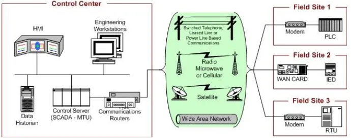
[image:18.612.152.497.550.686.2]SCADA is an acronym for Supervisory Control and Data Acquisition. SCADA systems are highly distributed systems used to control geographically dispersed assets, often scattered over thousands of square kilometers, where centralized data acquisition and control are critical to the system operation. SCADA is the technology that enables a user to collect data from one or more distant facilities and/or send limited control instructions to those facilities. SCADA makes it unnecessary for an operator to be assigned to stay at or frequently visit remote locations when those remote facilities are operating normally. SCADA includes the operator interface and the manipulation of application-related data but it is not limited to that[1].
5
SCADA systems consist of[1,5]:
• One or more field data interface devices, usually RTUs, or PLCs, which interface to field sensing devices and local control switchboxes and valve actuators.
• Communications systems used to transfer data between field data interface devices and control units and the computers in the SCADA central host. The system can be radio, telephone, cable, satellite, etc., or any combination of these.
• A central host computer server or servers (sometimes called a SCADA Center, master station, or Master Terminal Unit (MTU).
• A collection of standard and/or custom software [sometimes called Human Machine Interface (HMI) software or Man Machine Interface (MMI) software] systems used to provide the SCADA central host and operator terminal application, support the communications system, and monitor and control remotely located field data interface devices.
2.1.1. Definition of SCADA[1]
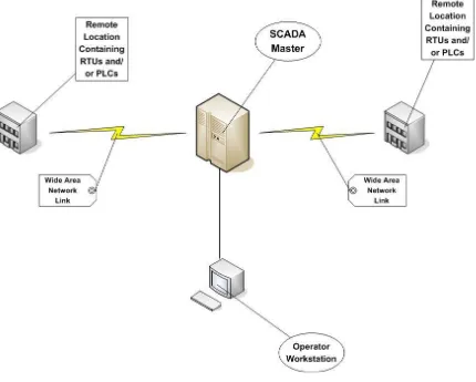
visits to monitor facility operation. The value of these benefits will grow even more if the facilities are very remote and require extreme effort (e.g., a helicopter trip) to visit.
Figure 2.2: Typical SCADA System
2.1.2. Control Components
The following is a list of the major control components of SCADA[2]:
7
Remote Terminal Unit (RTU). The RTU, also called a remote telemetry unit, is special purpose data acquisition and control unit designed to support SCADA remote stations. RTUs are field devices often equipped with wireless radio interfaces to support remote situations where wire-based communications are unavailable. Sometimes PLCs are implemented as field devices to serve as RTUs; in this case, the PLC is often referred to as an RTU.
Human-Machine Interface (HMI). The HMI is software and hardware that allows human operators to monitor the state of a process under control, modify control settings to change the control objective, and manually override automatic control operations in the event of an emergency. The HMI also allows a control engineer or operator to configure set points or control algorithms and parameters in the controller. The HMI also displays process status information, historical information, reports, and other information to operators, administrators, managers, business partners, and other authorized users. The location, platform, and interface may vary a great deal. For example, an HMI could be a dedicated platform in the control center, a laptop on a wireless LAN, or a browser on any system connected to the Internet.
Data Historian. The data historian is a centralized database for logging all process information within an ICS. Information stored in this database can be accessed to support various analyses, from statistical process control to enterprise level planning.
2.1.3. Applicable Processes
SCADA technology is best applied to processes that are spread over large areas are relatively simple to control and monitor; and require frequent, regular or immediate intervention. The following example of such processes shows the range of application types SCADA is suitable for[3,6]:
A. Groups of small hydroelectric generating stations that are turned on and off in response to customer demand are usually located in remote locations, they can be controlled by opening and closing valves to the turbine, they must be monitored continuously and they need to respond relatively quickly to demands on the electric power grid.
B. Oil or gas production facilities including wells, gathering systems, fluid measurement equipment and pumps are usually spread over large areas, require relatively simple controls such as turning motors on and off, need to gather meter information regularly and must respond quickly to conditions in the rest of the field.
C. Pipeline for gas, oil, chemicals or water have elements that are located at varying distances from a central control point, can be controlled by opening and closing valves or starting and stopping pumps and must be capable of responding quickly to market conditions and to leaks of dangerous or environmentally sensitive materials.
D. Electric transmission systems may cover thousands of square kilometers, can be controlled by opening and closing switches and must respond almost immediately to load changes on the lines.
9
SCADA has been successfully installed on each of these types of processes as well as many others. Typical signals gathered from remote locations include alarms, status indications, and analog values and totalized meter values. However, a vast range of information can be gathered with this apparently limited menu of available signal types.
2.1.4. Considerations and Benefits of SCADA System
Typical considerations when putting a SCADA system together are[3]:
Overall control requirements Sequence logic
Analog loop control
Ratio and number of analog to digital points Speed of control and data acquisition
Master/operator control stations Type of displays required
Historical archiving requirements System consideration
Reliability/availability
Speed of communications/update time/system scan rates System redundancy
Expansion capability
Obviously, SCADA systems initial cost has to be justified. A few typical reasons for implementing a SCADA system are[3]:
Improved operation of the plant or process resulting in savings due to optimization of the system.
Increased productivity of the personnel.
Improved safety of the system due to better information and improved control.
Protection of the plant equipment.
Safeguarding the environment from a failure of the system. Improved energy savings due to optimization of the plant.
Improved and quicker receipt of data so that clients can be invoiced more quickly and accurately.
Government regulations for safety and metering of gas (for royalties & tax etc).