Copyright © 2012 CTTS.IN, All right reserved
Implementation of Fully Automated Electricity for large
Building Using SCADA Tool like LabVIEW
Basil Hamed
Electrical Engineering, Islamic University of Gaza, Gaza, Palestine. Email:[email protected]
Abstract — This paper deals with the development and implementation of a framework of SCADA using LabVIEW based Data Acquisition and Management. A SCADA system is described in terms of architecture, process interfaces, functionality, and application development facilities. The system is low on system requirements and easy to implement. This paper describes configuration of Remote Terminal Units to access and transmit real time data over the Intranet, logging all the data in a historian for future references at a centralized location, keeping the human operator updated via Human Machine Interface, and providing measures for any emergency and enabling control via SMS giving true remote control capabilities. In addition, the project can automatically run the suitable generator from his reading of the foundation power; in short it’s the best solution of the foundation electricity problem.
Keywords—SCADA, PLC, Lab VIEW.
1. I
NTRODUCTIONFor the last few decades, Programmable Logic Controller (PLC) has been widely accepted in various process industries which is a solid state device designed to perform logic functions [1]. PLC has several known features including, flexibility, reliability, low power consumption and ease of expandability. The software abstraction level changes mere requirement in extending and optimizing the control process rather than internal rewiring [2, 3]. Industrial control system (ICS) is a general term that encompasses several types of control systems, including supervisory control and data acquisition (SCADA) systems, distributed control systems (DCS), and other smaller control system configurations such as skid-mounted Programmable Logic Controllers (PLC) often found in the industrial sectors and critical infrastructures. ICSs are typically used in industries such as electrical, water, oil and gas, chemical, transportation, pharmaceutical, pulp and paper. SCADA systems became popular to arise the efficient monitoring and control of distributed remote equipment’s [4]. PLC can have the communication with SCADA through tags of information [5]. In literature, many reports are found pertinent to successful integration of PLC with SCADA for number of applications [6, 7]. Today SCADA systems include operator-level software applications for viewing, supervising and troubleshooting local machines and process activities. Powerful software technologies are used for controlling and monitoring
equipment’s in easy-to-use web-based applications. In today scenario in control industries, many more sophisticated instruments are introduced which supports higher data rate. The new enhancements made in the automation of industrial processes have been realized through OPC server [8, 9].
2. SCADA
A. SCADASCADA is an acronym for Supervisory Control and Data Acquisition. SCADA systems are used to monitor and control a plant or equipment in industries such as telecommunications, water and waste control, energy, oil and gas refining and transportation. These systems encompass the transfer of data between a SCADA central host computer and a number of Remote Terminal Units (RTUs) and/or Programmable Logic Controllers (PLCs), and the central host and the operator terminals. A SCADA system gathers information (such as where a leak on a pipeline has occurred), transfers the information back to a central site, then alerts the home station that a leak has occurred, carrying out necessary analysis and control, such as determining if the leak is critical, and displaying the information in a logical and organized fashion. These systems can be relatively simple, such as one that monitors environmental conditions of a small office building, or very complex, such as a system that monitors all the activity in a nuclear power plant or the activity of a municipal water system. Traditionally, SCADA systems have made use of the Public Switched Network (PSN) for monitoring purposes.
Today many systems are monitored using the infrastructure of the corporate Local Area Network (LAN)/Wide Area Network (WAN). Wireless technologies are now being widely deployed for purposes of monitoring
B. Components of SCADA systems
A SCADA system is consist of many components that is build wide control and supervision .The main components are:
Copyright © 2012 CTTS.IN, All right reserved 3) A central host computer server or servers (sometimes
called a SCADA Center, master station, or Master Terminal Unit (MTU)
4) A collection of standard and/or custom software [sometimes called Human Machine Interface (HMI) software or Man Machine Interface (MMI) software] systems used to provide the SCADA central host and operator terminal application, support the communications system, and monitor and control remotely located field data interface devices. Figure 1 shows a typical SCADA system. Each of the above system components will be discussed in detail in the next sections.
Fig.1. SCADA System
The communications network is intended to provide the means by which data can be transferred between the central host computer servers and the field-based RTUs. The Communication Network refers to the equipment needed to transfer data to and from different sites. The medium used can either be cable, telephone or radio. Remote sites are usually not accessible by telephone lines, and the use of cable is not practical for systems covering large geographical areas because of the high cost of the cables, conduits and the extensive labor in installing them. The use of radio offers an economical solution. Radio modems are used to connect the remote sites to the host. An on-line operation can also be implemented on the radio system. For locations where a direct radio link cannot be established, a radio repeater is used to link these sites.
C. Central Host Computer
The central host computer or master station is most often a single computer or a network of computer servers that provide a man-machine operator interface to the SCADA system. The computers process the information received from and sent to the RTU sites and present it to human operators in a form that the operators can work with. Operator terminals are connected to the central host computer by a LAN/WAN so that the viewing screens and associated data can be displayed for the operators. Recent SCADA systems are able to offer high resolution computer graphics to display a graphical user interface or mimic screen of the site or water supply network in question. However, with the increased use of the personal
computer, computer networking has become commonplace in the office and as a result, SCADA systems are now available that can network with office-based personal computers. Indeed, many of today's SCADA systems can reside on computer servers that are identical to those servers and computers used for traditional office applications. This has opened a range of possibilities for the linking of SCADA systems to office-based applications such as GIS systems, hydraulic modeling software, drawing management systems, work scheduling systems, and information databases.
D. Operator Workstations and Software Components
Operator workstations are most often computer terminals that are networked with the SCADA central host computer. The central host computer acts as a server for the SCADA application, and the operator terminals are clients that request and send information to the central host computer based on the request and action of the operators. An important aspect of every SCADA system is the computer software used within the system. The most obvious software component is the operator interface or Man Machine Interface/Human Machine Interface (MMI/HMI) package; however, software of some form pervades all levels of a SCADA system. Depending on the size and nature of the SCADA application, software can be a significant cost item when developing, maintaining, and expanding a SCADA system. When software is well defined, designed, written, checked, and tested, a successful SCADA system will likely be produced.
E. SCADA Architectures
SCADA systems have evolved in parallel with the growth and sophistication of modern computing technology. The following sub-sections will provide a description of the following three generations of SCADA systems:
First Generation–Monolithic Second Generation–Distributed Third Generation–Networked 1. Monolithic SCADA Systems
Copyright © 2012 CTTS.IN, All right reserved Fig.2. Typical First Generation SCADA Architecture
2. Distributed SCADA Systems
The next generation of SCADA systems took advantage of developments and improvement in system miniaturization and Local Area Networking (LAN) technology to distribute the processing across multiple systems. Multiple stations, each with a specific function, were connected to a LAN and shared information with each other in real-time. These stations were typically of the mini-computer class, smaller and less expensive than their first generation processors. Some of these distributed stations served as communications processors, primarily communicating with field devices such as RTUs. Figure 3 depicts typical second generation SCADA architecture.
Fig.3.Typical Second Generation SCADA Architecture
3. N
ETWORKEDSCADA S
YSTEMSThe current generation of SCADA master station architecture is closely related to that of the second generation, with the primary difference being that of open system architecture rather than a vendor controlled, proprietary environment. There are still multiple networked systems, sharing master station functions. There are still RTUs utilizing protocols that are vendor-proprietary. The major improvement in the third generation is that of opening the system architecture, utilizing open standards and protocols and making it possible to distribute SCADA functionality across a
WAN and not just a LAN. The major improvement in third generation SCADA systems comes from the use of WAN protocols such as the Internet Protocol (IP) for communication between the master station and communications equipment. This allows the portion of the master station that is responsible for communications with the field devices to be separated from the master station “proper” across a WAN. Vendors are now producing RTUs that can communicate with the master station using an Ethernet connection. Figure 4 represents a networked SCADA system.
Fig.4. Networked SCADA System
F. SCADA Protocols
60870-Copyright © 2012 CTTS.IN, All right reserved 5 series, specifically IEC 60870-5-101 (commonly
referred to as 101) and Distributed Network Protocol version 3 (DNP3).
4. H
ARDWAREC
OMPONENTSA control board consists of two circuits: A power circuit and a control circuit. The power circuit is used for high current; connecting the electric power to the load while the control circuit is a low current circuit implements the method in which the drivers of the load are excited. It may contain switches, push buttons, relays, timers, and counters. The drivers of the load are likely to be contactors, relays, or solid state relays.
A. Control circuit
Delta’s DVP-20EX200 series PLC [10]
The PLC takes the input from external computer or sensor, and the output is actuator as shown in Figure.
Fig.5. PLC System
Relay B. Power Circuit
Circuit Breaker Toggle Switch Current Transformer Contactor
5. S
OFTWARET
OOLSThere are several alternative SCADA packages which enable users to build their own customized screens for a particular controlled process. These packages are such as: LabVIEW, Wonderware's InTouch, Citect SCADA, RsView32, Siemens WinCC and other.
A. HMI for Project
We use LabVIEW software tools to implement HMI for this project. For building SCADA system, some modules are needed for LabVIEW software such as:
• NI LabVIEW Full Development System. • Real-Time Module.
• Data logging and Supervisory Control module. • Touch Panel Module.
• NI OPC Server.
B. LabVIEW 2009 Software Tool
The system is implemented on LabVIEW by National Instruments. Certain features like VI portability, Image Processing, availability of advanced processing kits, etc. favored this particular product’s choice [11]. LabVIEW is a graphical programming language that uses icons instead of lines of text to create applications. LabVIEW uses dataflow programming, where the flow of data determines execution. LabVIEW builds a user interface with a set of tools and objects. The user interface is known as the front panel. A code is then added using
graphical representations of functions to control the front panel objects. The block diagram contains this code. In some ways, the block diagram resembles a flowchart. LabVIEW contains the following three components
Front panel: Serves as the user interface.
Block diagram: Contains the graphical source code that defines the functionality of the VI.
Icon and connector pane: Identifies the VI so that can be used in another VI. A VI within another VI is called a sub VI. A sub VI corresponds to a subroutine in text-based programming languages.
Palettes: LabVIEW palettes give the options need to create and edit the front panel and block diagram. C. DSC Module
The DSC Module extends the LabVIEW graphical development environment with additional functionality for the rapid development of distributed measurement, control, and high-channel-count monitoring applications. The DSC Module also enhances the LabVIEW shared variable. Use the shared variable to access and pass data among several VIs in a LabVIEW project or across a network. A shared variable can represent a value or an I/O point. With the DSC Module, you can log data automatically; add alarming, scaling, and security to the shared variable; and configure the shared variable programmatically. The DSC Module also provides tools for graphing historical or real-time trends, enhancing the security of front panels, and writing custom I/O servers. You can read or write to OLE for Process Control (OPC) connections, programmable logic controllers, or custom I/O servers that you write. The DSC Module provides solutions for supervisory control of a wide variety of distributed systems using graphical LabVIEW programming.
D. NI OPC Servers
Copyright © 2012 CTTS.IN, All right reserved OPC Server which allows a client application to access
data from many OPC Servers provided by many different OPC vendors running on different nodes via a single object as shown in Figure 6.
Figu.6. OPC Client/ Server Relationship
E. DataSocket VIs in LabVIEW
DataSocket is a technology for sharing data between applications or different data sources. You can connect to an OPC server with DataSocket using an OPC URL, which is similar to the URLs used in a Web browser. URLs provide a standard mechanism for referring to locations. DataSocket can share live data with one or more client applications on a network without worrying about data formats and network protocols. LabVIEW applications can easily share live data with a variety of clients, including Visual Basic applications, Web browsers, Visual C++, Microsoft Excel, LabWindows/CVI, and other LabVIEW applications. Using DataSocket technology, you can publish and receive data from any application in the same way, giving you the power to connect diverse applications easily.
6. S
IMULATIONFor getting more clear result, the proposed SCADA will be simulated firstly in order to test its distinguishing ability and fast ability in response. At last, the SCADA will be applied to real time application; the Shifa Hospital in Gaza has been taking as case study. Gaza, Palestine is suffering of electricity shortage, many independent generators are used to overcome the electricity shortage, the proposed SCADA is designed to organized and control the electricity in Shifa Hospital.
A. Steps of Aplying SCADA
The flow chart technique is applied to explain the steps of SCADA.
Fig.7. Starting Steps
The process of ON municipality electricity status and the OFF municipality electricity status are showed in Figure 8, and Figure 9 respectfully. A transformer is connected to a processing circuit before connect it to the input channel of the PLC. To read the voltage a simple transformer is used which has an analog DC output and connect it to the input channel of the PLC
ON Municipality Electricity
Fig.8. Municipality Electricity is ON
Copyright © 2012 CTTS.IN, All right reserved available (Non-Essential load, Essential load, and
Essential-Essential load).
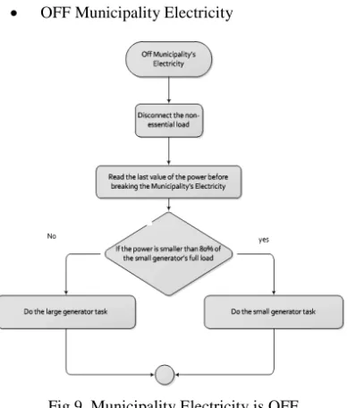
OFF Municipality Electricity
Fig.9. Municipality Electricity is OFF
The user can read the total power by computing it using the current, and the voltage values; also can connect the Non-essential load using the button in the interface program which mentioned in the previous chapters B. HMI Using LabVIEW Software
The user has full accessibility to the project, that’s mean monitor and control of the system anywhere in world.
Fig.10. Login Page
After the user connects to the system, he will reach the main page which contains; system monitor, system control, and alarms. The user can access any one as he like (control or monitor).
Figure 11.Main Page
When the user chooses the system monitor, the system monitor page will open and show the distribution power for whole system (power station, generators, distributed lines, indicators, contactors, and the loads). The user can know which load is on, the generators are on or off, and if there is any problem in the system.
Fig.12. System Monitor Page When Power Station ON
Copyright © 2012 CTTS.IN, All right reserved Fig.13. System Monitor Page When Power Station
OFF and Generator 1 ON
In Figure 13, the Details button are shown, when the button is push, then we will leave the system monitor page and go to the phase voltage and current monitor for the system. The user can monitor from here the phase voltage and 3-phase current as shown in Figure 14.
Fig.14. Detail Page
Press Back button to go back to the system monitor. There are three details button beside generators. These buttons will move you the page contain the status of generators and its specifications.
Fig.15. Detail Page for Generator 1 is ON
Fig.16. Detail Page for Generator 2 is OFF
Now, let’s go to the system monitor. First press the Back button which will go back to main page, then click on system control. Note, you have to change the status from control unit to be able to control the system from the software tools as shown in Figure 17.
Copyright © 2012 CTTS.IN, All right reserved C. Alarm System
Any monitor system may have fault or problem in the system, so that the engineer can see the problem and solve it. This proposed SCADA has alarms that the employees can see it in three ways:
1. Indicators: in this type of alarm the technician must be in the control room to see it.
2. Interface program: this type need an internet network to noticed.
3. SMS technique: this technique is the best way to insure that the alarms were noticed by the suitable employer.
Press the alarms button to see if there is any fault in the whole SCADA system as shown in Figure 18.
Fig.18. Alarm Page
Fig.19. sms sent to mobile
7. C
OMMUNICATIONS
ETTING:
The PLC is realized through MODBUS communication. Modbus RS232 is used to connect software tools with hardware components. Modbus RS232 have some properties as shown Figure 20.
Fig.20. Modbus RS232 Properties
8.
CONCLUSIONThis paper presents full design of SCADA systems to control the electricity in large building using LabVIEW software. The main goal of this paper is to achieve SCADA system using LabVIEW graphical programming language. With the network supported functions provided in LabVIEW, it is succeeded in developing an Intranet-SCADA System. Although a real time system Shifa Hospital which is the biggest hospital in Gaza is used for demonstration, the LabVIEW program which we have developed is not limited to any specific application and in general, can be used for any SCADA implementation. The proposed SCADA has been tested using LabVIEW software also has been applied in real time and showed very good result.
9. A
CKNOWLEDGMENTI would like to thank and express my appreciation to the engineers; Suliman M. Abu Tayyem, Abdullah Z. Al-Kurdi, Ayman M. Ismail, Hussien A. Keshta, and Hassan S. Al-Nahhal for their hard work in this project. (This project was their senior project as electrical engineering department requirement for graduation).
10. R
EFERENCES[1] W. Bolton, Programmable logic controllers, Newnes: 2009
[2] James A. Rehg, Glenn J. Sartori, Programmable logic controllers, Prentice Hall: 2007
[3] Frank D. Petruzella, Programmable logic controllers, Tata McGraw-Hill Education: 2005 [4] Stuart A. Boyer, SCADA: supervisory control and
data acquisition, International Society of Automation: 2009
Copyright © 2012 CTTS.IN, All right reserved in refinery application” Computer Standards &
Interfaces, vol. 31, p. 599-612, March 2009
David Bailey and Edwin Wright, “2- SCADA systems, hardware and firmware” in Practical SCADA for Industr: 2003, 11-63
[6] Vinay M. Igure,Sean A. Laughtera, and Ronald D. Williamsa, “Security issues in SCADA networks” Computers & Security, vol. 25, p. 498- 506, October 2006
[7] Cihan Sahina, and Emine Dogru Bolatb, “Development of remote control and monitoring of web-based distributed OPC system”, Computer Standards & Interfaces, vol. 31, p. 984-993, September 2009
[8] Xu Hong, and Wang Jianhua, “An extendable data engine based on OPC specification”, Computer Standards & Interfaces vol. 26, p. 515- 525, October 2004
[9] http://www.delta.com.tw/industrialautomation [10] National Instruments ® LabVIEW ® User Manual.
April 2003 Edition