Theses
Thesis/Dissertation Collections
2009
Implementing QR Code Technology in Medical
Device Pacakage
Manu Chakravarthy Kittanakere Naagaraj
Follow this and additional works at:
http://scholarworks.rit.edu/theses
Recommended Citation
IMPLEMENTING QR CODE TECHNOLOGY IN MEDICAL
DEVICE PACKAGE
By
Manu Chakravarthy Kittanakere Naagaraj
A THESIS
Submitted to
Department of Packaging Science
College of Applied Science and Technology
In partial fulfilment of the requirement for the degree of
MASTER OF SCIENCE
Rochester Institute of Technology
•
Department of Packaging Science
College of Applied Science and Technology
Rochester Institute of Technology
Rochester, New York
CERTIFICATE OF APPROVAL
M. S. DEGREE THESIS
The M. S. Degree thesis of Manu Chakravarthy Kittanakere Naagaraj
has been examined and approved
by the thesis committee as satisfactory
Dr. Changfeng Ge, Advisor
Mr. Raymond Lareau, Member
Dr. Daniel Goodwin, Member
for the requirements for the
Master of Science Degree
111
DEDICATION
)
•
)
Implementing QR Code Technology in Medical Device Package
ACKNOWLEDGEMENTS
Department of Packaging Science Rochester Institute of Technology
I would like to express my deepest thanks to Dr. Changfeng Ge, my advisor, for his
educational and professional guidance and advice.
I would have not been able to successfully
complete this thesis without his help.
I
would also like to express my sincere heartfelt thanks to my committee member Mr.
Raymond Lareau for dedicating his time for me and helping me out at difficult times to
successfully complete my Thesis.
I also would like to express my sincere appreciation to Professor Deana Jacobs and
committee member Dr. Daniel Goodwin for their valuable advice and time.
)
ABSTRACT
IMPLEMENTING QR CODE TECHNOLOGY IN MEDICAL DEVICE
PACKAGE
By
Manu Chakravarthy Kittanakere Naagaraj
Implementing QR Code Technology in Medical Device Package
TABLE OF CONTENTS
Department of Packaging Science Rochester Institute of Technology
Dedication ... v
Acknowledgements ... vi
Abstract ... vii
Table of Contents ... viii
Table of Figures ... x
Chapter 1. Introduction ... 1
1.1 Motivation for this work ... 1
1.2 Overview of QR Code Technology ... 4
1.2.1 QR Code Structure ... 7
1.2.2 Characteristics of QR Code ... 8
1.2.3 QR Code Specification ... 13
1.2.4 Standardization of QR Code ... 13
1.3 Applications of QR Code technology ... 14
1.4 QR code v/s two-dimensional barcodes ... 15
1.5 Types of Two-Dimensional Barcodes ... 16
1.6 QR code v/s RFID ... 22
1.6.1 Introduction to Rf ID ... 22
1.6.2 Components of RFID ... : ... 22
1.6.3 Comparison of Rf ID with barcode ... 24
I. 7 QR code generating softwares and readers ... 27
1.8 QR code Phones and Scanners ... 28
1.9 Limitations oflmplementing QR Code Technology ... 29
Chapter 2. Introduction to Medical Device Package ... 31
2.1 Components of Medical Device Package and its effects ... 31
2.1.1 Device ... 31
2.1.2 Tyvek Pouch / Tray ... 31
2.1.3 Labelling in Medical Device Package ...
32
2.1.4 Climatic Conditioning and Accelerated Aging ... 32
2.1.5 Types of defects in a Medical Device Package ... 33
2.1.6 IFU's, Nurse's guide, Patient guide / Card ... 34
2.1.7 Labelling ... 34
Chapter 3. Overview of the Thesis ... 37
3.1 Introduction ... 37
3.2 Problem statement ... 37
3 .3 Purpose of Study ... 39
3.4 Methodology ... 39
3.5 Deliverables ... 40
3.6 Implications of the research within the industry ... 40
Chapter 4. Development Process of QR Code Technology ... 41
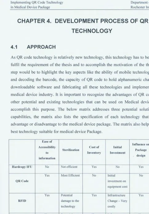
4.1 Approach ... 41
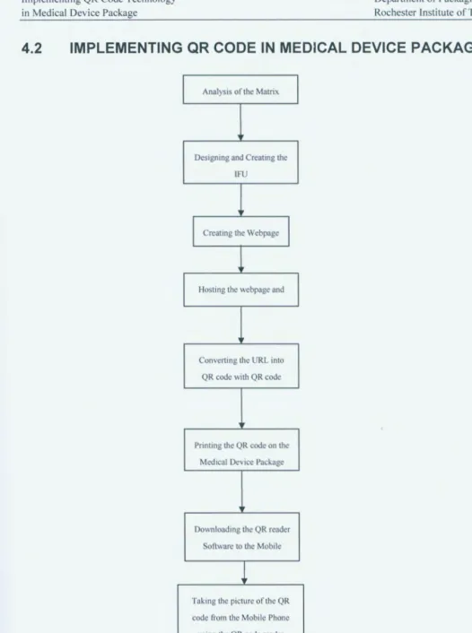
4.2 Implementing QR code in Medical Device Package ... 44
4.2.1 Webpage layout design for IFU ... 45
4.2.2 Dreamweaver Software ... 45
4.2.3 Hosting the webpage ... 46
4.2.4 Creating the QR Code on a Package ... 46
4.2.5 Development Procedure to create the QR code on a Medical Device
Package ... 47
4.3 Benefits of Implementing QR codes in Medical Device Package ... 49
4.4 Feasibility of QR code Technology in Medical Device Package ... 49
4 .4 .1 Device Classification ... i ... 49
4.4.2 Devices Benefited by the Technology ... 51
Chapter 5. Case study ... 57
5.1 Introduction ... 57
5.2 Market For Implantable Ports ... 57
5.3 Competitors for Implantable Ports ... 59
5.4 Assumptions for the New Technology ... 63
5.5 Procedure to build the prototype ... 64
5.6 Cost Analysis ... 76
Chapter 6. Conclusion ... 81
Reference ... 84
Implementing QR Code Technology in Medical Device Package
TABLE OF FIGURES
Department of Packaging Science Rochester Institute of Technology
Figure 1.1. Hierarchy and development of QR code
3•••••••••••••••••••••••••••••••••••••••••••••••••••••••••••••••.••• 5
Figure 1.2. Evolution to Two-Dimensional barcode ... 5
Figure 1.3. Comparison between one-dimensional barcode and QR code
1••••••••••••••••••••••••••••••••••• 6
Figure 1.10. QR Code Structure
3... 7
Figure 1.4. Multi-Directional Reading
2•
3... 9
Figure 1.5. Examples of distorted symbols
3... 9
Figure 1.6. Examples of smudged and damaged codes
3... 10
Figure 1.7. Linking functionality of QR Code
2•
3... 11
Figure 1.8. Masking Process
2•
3... 12
Figure 1.9. Working process of Direct Marking
3... 12
Figure 1.11. Specification table for QR Code
3... 13
Figure 1.12. Supercode
13... 17
Figure 1.13. PDF417
13... 17
Figure 1.14. Maxicode
16... 18
Figure 1.15. DataMatrix
16... 18
Figure 1.16. Code One
13... 18
Figure 1.17. Aztec Code ... 19
Figure 1.18. Comparison table between Two-Dimensional barcodes
1... 20
Figure 1.19. Advantages of QR Code
3... 21
Figure 1.20. Components of RFID Technology ... 23
Figure 1.21. Comparison table for Advantages and Disadvantages of Barcodes and
RFID ... 26
Figure 1.22. Screen shot of Kaywa software (QR code generating window)
2°... 27
Figure 1.23. QR code Scanners and Decoding devices ... 28
Figure 4.1. Matrix for assessing different technology for Medical Device Package ... 41
Figure 4.2. Flowchart showing working of QR code Technology ... 44
Figure 4.3. QR code Implementation analysis table ... 52
Figure 4.5. Flowchart showing Categories of Devices used when Necessary ... 54
Figure 4.6. QR code Feasibility analysis table for Diagnostic Spirometer ... 55
Figure 4.7. QR code Feasibility analysis table for Syringes ... 55
Figure 4.8. QR code Feasibility analysis table for Pacemaker ... 56
Figure 4.9. QR code Feasibility analysis table for Neurosurgical headrest.. ... 56
Figure 5.1. Picture of Bard Medical Implantable Port
23... 59
Figure 5.2
.
Picture of Smiths Medical Implantable Port ... 60
Figure 5.3. Picture ofNavilyst Medical Implantable Port ... 61
Figure 5.4. Picture of RITA Medical System Implantable Port ... 62
Figure 5.5. Screen shot of Text being prepared in Microsoft Word ... 64
Figure 5.6. Screen shot of Translation from English to French ... 65
Figure 5.7. Screen shot of Pictures being created in CorelDraw ... 66
Figure 5.8. Layout for the webpage designed in CorelDraw ... 67
Figure 5.9. Alignment of text and graphic in CorelDraw layout ... 68
Figure 5.10. Code created for webpage design ... 69
Figure 5.11. Page linking using Dreamweaver software with created code ... 70
Figure 5.12. Code created for webpage design in Dreamweaver software ... 71
Figure 5.13. Linking the languages to the appropriate pages in Dreamweaver ... 72
Figure 5.14. Screen shot of home page ofFilezilla Software ... 73
Figure 5.15. Picture of QR code Generating software window (Kaywa Software) ... 74
Figure 5.16. Picture of generated QR code in Kaywa Software ... 74
Figure 5
.
17
.
QR Code printed on the prototype of Medical Device Package ... 75
Figure 5.
1
8
.
Statistical Analysis of Cost per IFU for 4 companies ... 79
Figure 5.
1
9
.
Cost Analysis of IFU cost for the year 2008 for each company ... 80
Figure 6.1. Table and Cost analysis for the average number of page for each literature
type ... 82
Implementing QR Code Technology
in Medical Device Package Rochester Institute of Technology Department of Packaging Science
CHAPTER 1. INTRODUCTION
1.1
MOTIVATION FOR THIS WORK
The main motivation of the research is saving cost by implementing new emerging
technology by contributing to the field of sustainability. Cost reduction can be achieved by
reducing paper and printing costs; global warming can be reduced by eliminating paper use
and it also supports sustainability. Enhancing the functionality of any technology by cutting
cost and implementing lean manufacturing was also another motivation to this research.
Of secondary importance is the main demographic change influencing the Medical Device
industry is the rapidly growing number of elderly in the United States. The latest published
data from the Census Bureau shows that the percentage of people aged 65 and older will
increase from 12.4 percent in 2000 to an estimated 20.7 percent by 2050 based on the 2000
Census and published in early 2004
5.
According to Census estimates, there were about 35 million Americans over the age of 65 in
2000; due to the anticipated increase in overall life expectancy, by 2020 there will be more
than 54 million people 65 and older, and more than 86 million by 2050.
Due to the technology and facilities in the Medical device industry, the younger generation
have the probability of living longer, as they will be facilitated with sophisticated and long
term health care. This has driven the need for advanced medical health care and raised
expectations that new technologies will enhance the quality and length of a patient's life.
Another
important aspect to consider is the mergers and acquisitions within the medical
device industries. Due to the mergers, the larger companies are becoming more stable and
there could be a standardized structure followed by most of the firms. Larger companies
usually have a greater capability for exporting products globally. They are also better
positioned to negotiate with GPO's such as HMO's and health care companies nationwide
6•)
Most noticeable to consumers is the proliferation of on-line sites featuring product and
purchasing information. Institutional purchasers of medical equipment in the U.S. and
overseas are integrating on-line procurement into supply-chain management programs, saving
time and money. Patients are also gathering treatment and product information on the Internet
and are having more input in decisions affecting their health care. Medical device
manufacturers are realizing savings by an FDA regulatory change allowing device manuals to
be available online and through "electronic labelling." This change allows devices intended
for use in health care facilities to use electronic, rather than traditional paper, labelling, as
long as users have the option, upon request, of obtaining labelling in paper form.
E-commerce is changing medical device trade in other regulatory areas as well. In 1997, the
FDA implemented the Electronic Records and Signatures Regulation. This rule (21 CFR 11)
establishes the criteria under which the FDA will deem electronic records and electronic
signatures equivalent to paper records and traditional handwritten signatures.
While electronic filing should lighten the burden on manufacturers, there are significant
differences between electronic records and signatures and traditional paper systems that
necessitate additional controls. Issues relating to confidentiality, permanency and the integrity
of electronic signatures have challenged both the FDA and industry. However, as systems are
established and evaluated, electronic submissions will likely become standard.
Implementing QR Code Technology in Medical Device Package
Department of Packaging Science Rochester Institute of Technology
It is important to recognize the enhancement in quality and technology in a medical device to
support all the above aspects. Due to the steady growth in population, the US is targeting many international markets and focusing more on high technology medical devices. China, including the Special Administrative Region of Hong Kong, is the second largest market for U.S. medical device exports in Asia. U.S. medical device exports to China will increase 5 to
10 percent annually for the near future. U.S. medical device exports to China totalled $805 million in 2004. China's overall market for medical equipment and supplies was estimated at $2.5 billion in 2005. Many in the industry believe this figure understates the actual size of China's market. Japan's medical device market, estimated to exceed $17 billion in 2005, is
the largest market for the U.S. medical equipment and supplies companies. U.S. exports to Japan have increased from $2.24 billion in 1999 to $2.7 billion in 2004, which is slightly below the peak level of exports ($2.73 billion) reached in 2001. Medical device-related trade issues with Japan are being addressed in the Market-Oriented, Sector-Selective (MOSS) Agreement signed on January 9, 1986. It has served since then as the basis for continuous bilateral discussions to improve market access for American exporters of pharmaceuticals, cosmetics and medical devices. Korea and Taiwan are also in the top 20 markets for U.S.
medical and dental products, where U.S. exports in 2004 were valued at $668 million8•
Finally, International harmonization of regulatory requirements expands the opportunities for exports. Most of the Asian countries are the fastest growing markets for the U.S. medical
1.2
OVERVIEW OF QR CODE TECHNOLOGY
QR Code is used in Japan in wide range of application. They were first used in supply chain
application by an automobile manufacturer to track automobile parts. The QR code has
dominated the market due to its unique advantages and compatibility. It is an effective
labelling technology that can be compared with RFID, one-dimensional barcodes and
nanotechnology.
Denso wave
created QR code in 1994, it can be associated with two-dimensional barcode that
can hold more information compared to conventional barcode horizontally and vertically. QR
code stands for quick response code. QR code might be the future and have the potential to
replace one-dimensional barcode. Various industries have made efforts to increase the
amount of information stored by a traditional barcode such as increasing the number of
barcode digits or laying out multiple barcodes. However, these improvements also caused
problems such as enlarging the barcode area, complicating reading operations and increasing
printing cost. Thus, QR code has been emerging rapidly and is being used in different
industries
.
Below are the reasons for QR code being implemented in most of the
applications
1•
2:
• QR code can hold much higher data density and support different foreign symbols
like Chinese/Kanji characters compared to linear barcode.
• QR code can be used by anybody without any cost and can be created without any
license as Denso wave has related the patent into the public domain.
• Data structure standard is not prerequisite for any application making the QR code
more versatile and flexible.
• Most of the camera phones have their own software to decode the QR code. The
software can be downloaded free or is preloaded in the phone.
•
Implementing QR Code Technology
in Medical Device Package Rochester Institute of Technology Department of Packaging Science
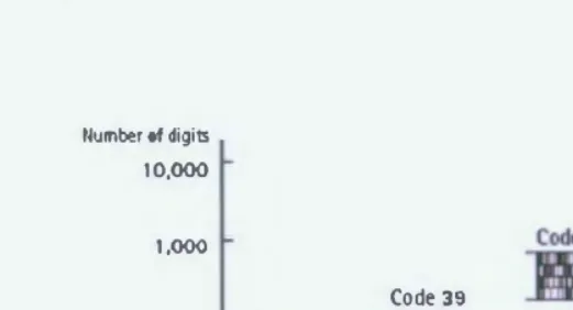
recent years, requests had mounted for symbols that can store more information and represent
languages other than English. To enable this, a symbol with even higher density than
multistage symbols was required. As a result, QR Code, that can contain 7,000 digits of
characters at maximum including Kanji characters (Chinese characters used in Japan), was
developed in 1994.
llumber of digits 10,000
1,000
100
10
Code 39·
�
mW
QR code
-11-UPC cod� Code 16K
�--�----�---�---�---�- Year
[image:16.761.133.394.208.349.2]1970 1975 1980 1985 1990
Figure 1.1. Hierarchy and development of QR code3
Linear
Matrix Symbol
Figure 1.2. Evolution to Two-Dimensional barcode Code 49
Multistage symbol
•
'
QR Code carries information both horizontally and vertically. This feature enables it to store
large amounts of data. In regards to space, QR Code is capable of encoding the same amount
of data in approximately one-tenth the space of a traditional bar code.
[image:17.754.213.363.153.189.2]1111
1
1
1
1
1
111
1
1111
1
1
1
1
1
�
1
1
1
�
1
1
11
11
11
11
1
1
1
1
1
... �lij ..,.. t;Jf1 11 I 2 3 4 5 6 7 8 9 0 I 2 5Figure 1.3. Comparison between one-dimensional barcode and QR code1
This feature makes the QR code versatile so it can be accommodated easily if there is an area
constrain. QR Code is also comprised of error correction capability. Data is restored even if
the symbol is partially unreadable or damaged. QR Code makes itself capable for 360 degree
high-speed reading; it accomplishes this task through position detection patterns located at
the three comers of the symbol. These position detection patterns guarantee stable high-speed
reading. The other advantage of QR code has been its ease of use .
Implementing QR Code Technology in Medical Device Package
1.2.1 QR Code Structure
Department of Packaging Science Rochester Institute of Technology
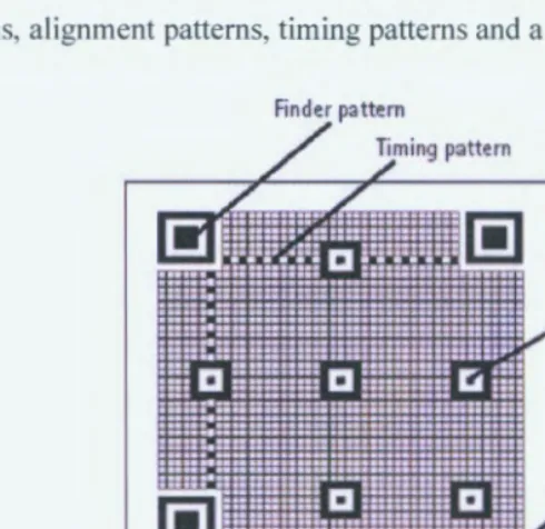
QR Code is a matrix-type symbol with a cell structure arranged in a square. [t consists of the
functionality patterns that makes reading easy and recognizes data area quicker. QR Code has
finder patterns, alignment patterns, timing patterns and a quiet zone.
Finder pattern
/ ;ming pattern
l!]
•
~~Alignment pattern
•
•
,rCell
•
•
) /
[image:18.754.154.399.166.404.2]Quiet zone
Figure 1.4. QR Code Structure3
a) Finder Pattern
Finder pattern is used in detecting the position of the QR Code. By arranging this pattern at
the three corners of a symbol the position, the size and the angle of the symbol can be
detected. This finder pattern consists of a structure that can be detected in all directions
(360°).
b) Alignment Pattern
This pattern is used for correcting the distortion of the QR Code. It is highly effective for
correcting nonlinear distortions. The central coordinate of the alignment pattern will be
identified to correct the distortion of the symbol. For this purpose, a black isolated cell is
placed in the alignment pattern to make it easier to detect the central coordinates of the
c) Timing Pattern
This pattern identifies the central coordinate of each cell in the QR Code with black and
white patterns arranged alternately. It is used for correcting the central coordinate of the data
cell when the symbol is distorted or when there is an error for the cell pitch. It is arranged in
both vertical and horizontal directions.
d) Quiet Zone
Quiet zone is a margin space required for reading the QR Code. This quiet zone makes it
easier to have the symbol detected from among the images read by the CCD sensor. Four or
more cells are necessary for the quiet zone.
e) Data Area
The QR Code data will be stored (encoded) into the data area. The data will be encoded into
binary numbers of 'O' and '1' based on the encoding rule. These binary numbers will be
converted into black and white cells and then will be arranged. The data area will have Reed
Solomon codes incorporated for the stored data and the error correction functionality.
1.2.2 Characteristics of QR Code
Additional
to the characteristics of two-dimensional symbols such .as large volume data
(7,089 numerical characters at maximum), high-density recording (approx. 100 times higher
in density than linear symbols) and high-speed reading, QR Code has superiority in both
performance and functional aspects.
a) Multi-directional Reading
)
Implementing QR Code Technology
in Medical Device Package Rochester Institute of Technology Department of Packaging Science
the position of the symbol arranged in three comers to enable high-speed reading in all
directions (360
°). The ratio between black and white among the scan line that runs through
the finder patterns is always 1: 1 :3: 1: 1 when seen from any direction among the 360
°surrounding it. By detecting this specific ratio, the finder pattern is detected and hence the
position of the QR Code is determined in a short period of time. Additionally, by identifying
the positional relationships of the three finder patterns listed in Figure 1.4 from the scanned
code captured in CCD sensor, the size (L), the angle (8), and the outer shape of the symbol is
simultaneously detected. By arranging the finder patterns into the three comers of the
symbol, the decoding speed of the QR Code becomes 20 times faster than that of other matrix
symbols.
(bl (a)
(cl
(3) 1 1 3 1 1
1 1 3 1 1
(b)�
1 1 3 1 1 (c)
�
Figure 1.5. Multi-Directional Reading2'3
b) Resistance to Distorted Symbols
Symbols often distort when they are attached onto a curved surface and/or variations in the
reader being tilted (angled between the CCD sensor face and the symbol face). To correct this
distortion, QR Code has alignment patterns arranged with a regular interval within the range
of the symbol. The variance between the centre position of the alignment pattern estimated
from the outer shape of the symbol and the actual centre position of the alignment pattern will
be calculated to have the mappings (to identify the centre position of each cell) corrected.
This mapping features helps to decode the QR code easily and accurately.
Estimated centre position
Correct the variance
Figure 1.6. Examples of distorted symbols3
c) Data Restoration Functionality (Resistance to Smudged or Damaged Symbols)
QR Code has four different error correction levels (7%, 15%, 25% and 30% per symbol area).
The error correction functionality is implemented according to the smudge/damage and is
utilizing Reed-Solomon code that is highly resistant to burst errors. Reed-Solomon codes are
arranged in the QR Code data area. By this error correction functionality, the codes can be
read correctly even when they are smudged or damaged depending on the error correction
level embedded in the QR Code. The user can configure the error correction level when the
symbol is created depending on the severity of the environment.
[image:21.756.139.418.250.337.2]�ll
�Figure 1. 7. Examples of smudged and damaged codes3
d) Efficiently Encoding Kanji and Kana Characters
QR Code was designed on the premise that it will be used in Japan. The specifications for the
symbol have efficiently encoded JIS level 1 and 2 Kanji and Kana characters. When making
Japanese expressions using other two-dimensional symbols, the expression could be made in
binaries and would require 16 bits (2 bytes) for a single character, whereas QR Code has each
Japanese character encoded in 13 bits. This means that QR Code can have Japanese letters
encoded 20% more efficiently than the other two-dimensional symbols. In other words, if the
data volume is the same, the symbol can be generated in a smaller area. Codes in each
country will be using the language in that specific country and this functionality will enable
encoding of the specific language in an efficient manner, such as having Chinese characters
for China and Vietnamese for Vietnam, efficiently encoded.
e) Linking Functionality of the Symbols
Implementing QR Code Technology in Medical Device Package
Department of Packaging Science
Rochester Institute of Technology
symbols, and each symbol has an indicator showing how many symbols the original symbol
had been divided into and in which order that specific symbol would be among all divided
ones. This will enable the entire data to be edited and submitted to the computer regardless of
what order the symbols had been read by the reader. By this linking functionality, a large QR
Code can be broken into a smaller one such that the cell size and data capacity can be
manipulated and satisfy the limitations of the camera phone applications. The readers can
reconstruct the information stored in the multiple QR code symbols.
11
I
.
--.:
Figure 1.8. Linking functionality of QR Code2 ,3
t) Masking Process
By having special patterns to process masking, QR Code is enabled to have black and white
cells evenly arranged in a balanced order. To accurately finalize the data that had been read, it
is necessary to arrange the white and black cells in a well-balanced manner. This process
helps in preventing pattern duplication, avoids code misreading and decodes the code
quickly. There are eight mask patterns and assessment will be made for each mask pattern.
To determine best pattern, EX-OR calculation will be performed on all the eight patterns.
Then the number of unique patterns existing and the balance between the white cells and the
black cells will be assessed amongst the patterns. The mask pattern with the highest
assessment result along with the EX-OR calculation result will be selected and stored into the
•
•
Mask processing results
Masked patterns
Origin.'all pattern
Figure 1.9. Masking Process2 ,3
g) The Confidentiality of the Code
By making the relationship between the character type and the stored data unique for a
special usage, QR Code can be easily encrypted. Unless the conversion table between the
character type and the stored data is deciphered, no one will be able to read the QR Code .
h) Direct Marking
QR Code exerts superior readability even for symbols that are directly marked using laser or
dot pin markers. For directly marked symbols, the cell shape does not necessarily have to be
square as shown in Figure 1.9; it can also be circular. Even if the, white part (with high
reflectance) and the black part (with low reflectance) are inverted due to the angle of the
illuminating ray, the code can still be read in an accurate manner. It is also possible to read
from the backside of the symbol when it is marked upon a transparent material such as glass,
etc.
11D
-< Cirru lar cells > -< Black and v.h ite cells in,l!rted >
Direct m.arking
When seen from the back
•
-�
.
. . . ·I!]< Frontjback inverted >
Figure 1.10. Working process of Direct Marking3
rt>
When s.ccn fromthe front
•
·.
~
l:'I:., . •
Implementing QR Code Technology
in Medical Device Package
1.2.3 QR Code Specification
Department of Packaging Science
Rochester Institute of Technology
The table below shows a typical specification of QR code. The capability of QR code is
collectively listed together. Symbol size ranges from 21 X2 l cells - l 77X 177 cells with 4 cell
intervals. Numerical characters, Alphabets, Binary characters and Kanji characters can be
encoded into a QR code depending on the usage of each character ranging from 1817 - 7089.
The conversion efficiency also depends on the type of character used ranging from 3.3 - 13
cells per character. A single QR code can be fragmented into 16 different symbols. Error
correction feature in the QR code can be customized by 4 different options.
Min. 21x21 cell - Max. 177x177 cell (with 4-cells interval)
Numerical characters
Alphabets, signs
Binary (8 bit)
Kanji characters
Numerical characters mode
Alpha numerical/signs mode
Binary (8 bit) mode
Kanji character mode (13 bit)
Level L
level M
Level Q
Level H
7,089 characters at maximum
4,296 characters at maximum
2,953 characters at maximum
1,817 characters at maxi mum
3.3 cells/character
5.5 cells/character
8 cells/character
13 cells/character
Approx. 7°'b of the symbol area
restored at maximum
Approx. 15% of the symbol area restored at maximum
Approx. 25% of the symbol area restored at maximum
Approx. 30% of the symbol area
restored at maximum
[image:24.754.59.492.248.720.2]Possible to be divided into 16 symbols at maxi mum
Figure 1.11. Specification table for QR Code3
1.2.4 Standardization of QR Code
Below is the history of standardization of QR code by different organizations.
Standardization is important for recognition of any technology. Even though QR code
technology is relatively new, QR code has been recognized by many organizations in a short
period. As we can see, QR code is mostly recognized in Asian countries as it can efficiently
handle various languages and symbols familiar to these countries. QR code has potential to
•
•
t
• 1997 AIM International (Automatic Identification Manufacturers)
AIM-ITS97/001
• 1999 Japanese Industrial Standard JIS- X0510
• 1999 JAMA (Japan Automobile Manufacturers Association ) JAMA-EIE001
• 2000 ISO (International Organization for Standardization) TSO/IEC 18004
• 2000 Chinese National Standard GB/T 18284
• 2002 Korea National Standard KS-X/IEC 18004
• 2003 Vietnam National Standard TCVN7322
1.3
APPLICATIONS OF QR CODE TECHNOLOGY
Qr Code Technology is being used in various applications. McDonalds Japan has already
started using the QR codes on the "Burger Package". These codes contain all the nutritional
information encoded. In this case, people can benefit the easy access to the information
through QR code technology. This technology is chosen by Japan as most of the people have
the camera phone and access to the internet
10•
QR codes have made the sale easy for both consumer and the manufacturer. The QR code is
printed in the catalogue. When the customer scans the QR code on the catalogue, the order
directions are automatically sent to the wholesaler. This improves the efficiency of ordering
transaction
3The QR code technology improves the quality of a sushi bar. A QR code-reader monitors the
freshness of sushi by scanning the QR code on the sushi plate for time the particular plate has
been on the counter. If the time scanned is more than an hour, that particular sushi can be
disposed of to ensure the freshness of the sushi.
QR code
t
echno
l
ogy is used for a casino cruiser. The QR code printed on the ticket has the
passport number, address and name of the passenger. This helps to get the information
quickly and the passenger does not have to carry any important documents on him except the
QR code printed ticket throughout the cruise
3•
•
t
Implementing QR Code Technology
in Medical Device Package Rochester Institute of Technology Department of Packaging Science
The test tubes in blood banks are comprised of a QR code. This QR code carries the
information of the blood, and these test tubes are inserted into a tester which has a built in QR
code reader. The system automatically examines the inserted blood group. With the help of
the technology, a large data can be printed on a limited space, and this contributes to the
quality of the process" .
The QR codes are used in fast and convenient bill payments. The QR code printed on the bill
statement contains a URL that directly links to the webpage where you can pay the bill
online. This is specifically designed for the mobile phone users.
QR code can be seen on highway billboards in Japan large enough for the passing motorists
to scan the barcodes with their camera phones. Hospitals are using these codes in the
prescriptions to better convey the information to the pharmacist. QR codes are also printed on
meat and eggs that carries the information about expiration date and the name of the farmer
9•Nippon Airways have been using the QR codes on the cell phones instead of printed tickets.
Other countries embracing QR code include Philippines for newspaper advertising and Great
Britain for conducting tests on various sport articles
12• The QR code is gaining popularity
quickly and is applications are numerous.
1.4
QR CODE V/S TWO-DIMENSIONAL BARCODES
•
•
•
a) Data Capacity:
Unlike the traditional one-dimensional barcode, a two-dimensional
barcode can accommodate data horizontally and vertically. They can hold large numbers of
data ranging from 49 to more than 7000. Data stored in two-dimensional barcode can be
alphanumeric also .
b) Error Correction:
As linear barcodes are one dimensional, symbol damage to barcode
can be protected only through vertical redundancy. If the error is along the width, linear
barcode will be looking for error that cannot be detected. This leads to failure of decoding the
barcode and is time consuming, compared to two-dimensional which has error correction
capability and sophisticated error correction algorithms. Many two-dimensional barcode have
the capability to recover information even though 50% of barcode is destroyed
c) Orientation:
Two-dimensional barcode can be read primarily with charge coupled device
(CCD) camera, and these barcodes can be read in any orientation. This is not same with the
one-dimensional barcodes in which reader has to determine the orientation of the symbol.
Different types of two-dimensional barcodes have different kinds of target area. Maxi code
has the target area in the centre; Data matrix has a solid border on the perimeter. These target
areas allows the scanners to determine the angle and size of the symbol. Once this
determination has been made; any barcode can be decoded successfully.
d) Edge Independence:
For two-dimensional barcodes printing and reading tolerance may
not be given more importance, as these codes does not depend on varying element widths,
reading of the colour at the centre of each cell, these barcodes can be printed in very small
size maybe even to microscopic level. This feature helps to accommodate the barcode on any
particular area .
1.5
TYPES OF TWO-DIMENSIONAL BARCODES
•
•
•
•
Implementing QR Code Technology
in Medical Device Package Rochester Institute of Technology Department of Packaging Science
can be read by determining the colour at centre of each cell. They can also be considered as
visual representation of machine-executable electronic binary code. The details about the
different types of barcode are discussed below
13, 14,15,16:
[image:28.756.226.342.284.408.2]1.
Super code:Super code is one of the latest stacked two-dimensional barcode
developed by "Metanetics". More than 4000 characteristics can be encoded in a Super
code. The 2 important components of a Super code symbol are the address of the data
and the actual data. This unique feature of the Super code facilitates creation of the
code into different array of shapes. Super code can be seen in many public domains,
but AIM has not yet made this barcode as a standard. The below figure illustrates a
picture of a super code tailor made in different shapes .
Figure 1.12. Supercode13
2. PDF417:
Symbol technologies developed this code in 1990. PDF417 is also referred
as "Portable data file" because of its high capacity to hold more than 1800
alphanumeric characters. PDF4 l 7 can be called mixed code as it has similarities of
both stacked and matrix barcodes. To help the scanner and decoder keep track short
bar heights are implemented, which identifies the particular line being scanned. The
stacked barcode characteristics can be seen in this barcode as it has the feature of
encoding each line using different algorithm. As another barcode, it has both error
detection and error correction capabilities, but one major drawback of this technology
is that the compromise should be made between level of error correction and character
capacity.
•
•
•
•
3. Maxi code:
United Parcel Service developed Matrix code; it contains array of
interlocking hexagons that surround a circular pattern in a 1 inch square. The barcode
is specified to be a fixed size. Location and orientation of the code can be identified
by the circular pattern; this circular pattern is also called as bull's eye finder pattern
located in the centre. Two selectable levels of error correction can be encoded in this
code. Maxi code can hold about 92 characters in black, white or grey hexagons.
Figure 1.14. Maxicode16
4. Data Matrix: this type of matrix can recognize a checkerboard arrangement of black
and white squares. This type of barcode uses perimeter border to recognize the size,
location and orientation of the symbol. This code can be printed in very small sizes
and can be used for appropriate applications.
g
Figure 1.15. Data Matrix165. Code one: Laser Light Systems developed this barcode. It was accepted by ACM in
1996. Code one has a data capacity of 2218 characters. Maxi code varies in size
depending on the amount of data encoded
•
•
•
•
Implementing QR Code Technology
in Medical Device Package Rochester Institute of Technology Department of Packaging Science
6. Aztec Code: This barcode contains black and white square data modules. The target
area for Aztec code is a pattern of concentric square rings in the centre of the symbol.
It is the most flexible code in the line of error correction, as the user can select the
required number of error correction .
Figure 1.17. Aztec Code
To decode this two-dimensional code in real time is an important aspect to consider. Most of
these barcode require a human operator. The term real-time means to have a response time
satisfying the feeling of the operator. Generally, a decoding time of about 500 milliseconds is
acceptable.
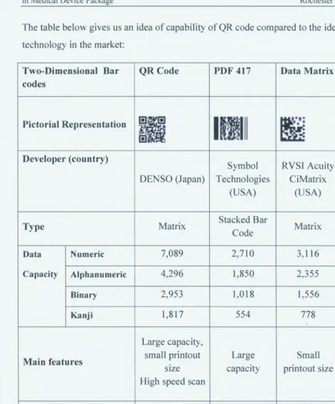
The table below gives us an idea of capability of
QR
code compared to the identicaltechnology in the market:
Two-Dimensional Bar QR Code PDF 417 Data Matrix Maxi code
codes
Pictorial Representation
Ii
1
11
1
11
e..·•:
,...
•
-
~
.
(~.
.
..
-:
?:'. •.Developer (country)
Symbol
RVSI
AcuityDENSO (Japan) Technologies CiMatrix UPS (USA)
(USA) (USA)
Matrix Stacked Bar Matrix Matrix Type
Code
Data Numeric 7,089 2,710 3,116 138
Capacity Alphanumeric 4,296 1,850 2,355 93
Binary 2,953 1,018 1,556
Kanji 1,817 554 778
Large capacity,
Main features small printout Large Small High speed
size capacity printout size scan
High speed scan
Main usages All categories OA FA Logistics
AIM
AIM
International AIM AIM
Standardization
JIS International International International
[image:31.754.49.521.66.633.2]ISO ISO ISO ISO
Implementing QR Code Technology
in Medical Device Package
High D3ta Capacity
I
l
l~ .
I
I
FDl'417OR code
~
ooW
Reduct Spact Printing
DJ.Tl. MATRIX
Department of Packaging Science
Rochester Institute of Technology
High Speed Reading
[image:32.754.52.570.23.655.2]M.U:I Codt
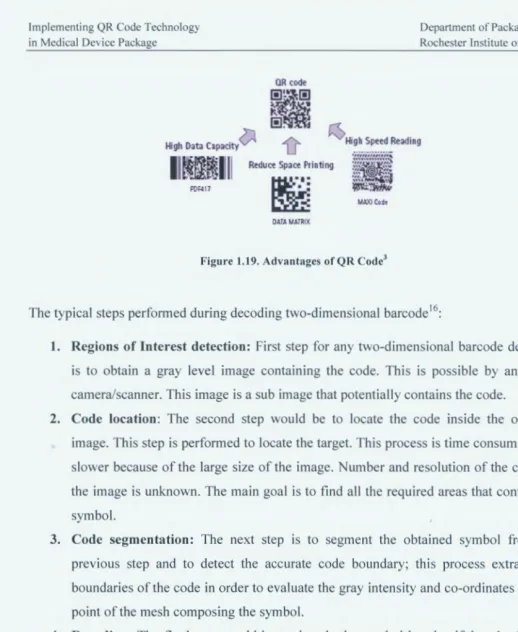
Figure 1.19. Advantages of QR Code3
The typical steps performed during decoding two-dimensional barcode16:
1. Regions of Interest detection: First step for any two-dimensional barcode decoding
is to obtain a gray level image containing the code. This is possible by any CCD
camera/scanner. This image is a sub image that potentially contains the code.
2. Code location: The second step would be to locate the code inside the obtained
image. This step is performed to locate the target. This process is time consuming and
slower because of the large size of the image. Number and resolution of the codes in
the image is unknown. The main goal is to find all the required areas that contain the
symbol.
3. Code segmentation: The next step is to segment the obtained symbol from the
previous step and to detect the accurate code boundary; this process extracts the
boundaries of the code in order to evaluate the gray intensity and co-ordinates of each
point of the mesh composing the symbol.
4. Decoding: The final step would be to decode the symbol by classifying the features
extracted using the syntactic rules of the symbol and translate the obtained
information in an ANSII string. This step also includes the key feature of a
•
t
•
1.6
QR CODE V/S RFID
1.6.1 Introduction to RFID
RFID is amongst very few technologies, which is making its mark in a rapid phase. The
tagging of RFID into the real world has been its major drive. RFID is definitely the future
technology that is going to take over other technologies. There has been a head-to-head
competition between RFID and barcode in the supply chain, but wide variety and versatility
of barcode is implemented in many other applications. RFID has potential to replace barcode
in supply chain. As RFID technology is relatively new compared to barcodes, there are
numerous factors acting against RFID like absence of standards, lack of regulatory
requirement and unknowns about it functionality in diverse conditions. Besides these
limitations, huge dominating companies like Wal-Mart and Metro are using RFID. RFID is
also being used in mobile application that has been very successful. RFID chips are been
enabled in mobile phones which can be used in different applications, one of the applications
is in airplane by switching off the mobile phones automatically and forcibly. There has been
other different application where RFID has been effectively used. A highly sophisticated
model can be built using RFID that allows 2 way communications between CPU and RFID,
Either RFID can be controlled by the CPU or CPU can control the RFID.
The basic working of RFID can be compared to that of a license plate numbering scheme and
many other different coding systems. Tag data acts as a reference to more detailed
information about the tagged object. The tag code has unique identifiers that link to the
information stored in the database. Complete required data can be stored on the tag, but it is
very expensive. RFID can also be considered as a pointer to the internet address in certain
applications. One of the major applications of RFID in medical field is "Surg chips". Surg
chip are used to store information such as date, patient's name, site of surgery, procedure to
be performed and surgeon's name. These chips can hold up to 256 characters. These tags are
stuck to the patient's skin and can be scanned by handheld reader for information. RFID tags
are also used in libraries to track the books online
17•18•19•
1.6.2 Components ofRFID
Implementing QR Code Technology in Medical Device Package
Department of Packaging Science Rochester Institute of Technology
frequency connector. The reader, in turn, connects via wired or wireless networks to servers
hosting RFID applications that make use of transmitted RFID data 17•
RFID Tags
Networ11
...
Eth•m•tWI.AN
ISDN
GPRS
Host Computer PC, Micn>controlef. DSP
Antenna
~
~
~
:-OJ
Figure 1.20. Components of RFID Technology
Tags contain microchip and a transponder. The microchip stores the data related to object and
the transponder transmits that data to readers. Tags can be programmed either during
manufacturing or by the end user. Each tag has its own unique identifier code depending on
the application and memory on the tag. There are 2 types of tags, Active tags and Passive
tags. Tags are activated when they enter the range of reader's signal. The power is sent to the
transponder through the reader's antenna activating the required data. Active tags are big in
size compared to passive tags and can hold more information. Active tags are expensive
compared to passive tags. Passive tags are mostly used in supply chain application. Passive
tags contain their own power source and the read range is more compared to the passive tags.
Tags can also be integrated with sensors. Tags can be printed on paper or plastic and can be
attached to any objects.
RF Connection
Tags transmit data to readers over different radio frequencies. Passive tags transmit
frequencies through different bands including high frequency, low frequency and ultra-high
frequency, whereas active tags are high frequency only. Regulatory body of each country,
•
•
•
•
•
RFID Readers
RFID readers are the most expensive component of RFID infrastructure. Mobile handheld
readers are also available and are being used extensively in supply chain. RFID readers are
also embedded in cell phones are becoming increasingly common. The main function of the
reader is to capture the information transmitted by a tag, decode it and deliver it to host
computer for further processing. All the latest readers use wireless technologies like
Bluetooth, Wi-Fi or WMax connections to transfer data.
1.6.3 Comparison of RFID with barcode
There are different cases where some of the newer optical tagging systems (Barcodes) could
compete with RFID. This is particularly true for consumer-oriented application involving
mobile phone readers where performance, cost and ease of use factors overrule RFID. But
both the technologies have its ups and downs. Choosing a particular technology depends on
the application. One major difference between barcodes and RFID is the camera phone with
the consumer that has a built-in barcode scanner. Consumers do not have to invest in a
dedicated scanning device, the only task for the consumer to tum their phones into scanners
to download the barcode reader on their camera phones. Even though RFID readers are also
being embedded in mobile phones, they are relatively new and those phones are expensive.
Other than giving consumer the ability to read object tags, these barcodes can be created by
the end user easily. Below are the comparison between the barcodes and RFID considering
some of the key features 18:
a) Affordability
•
•
•
•
Implementing QR Code Technology in Medical Device Package
b) Ease of use
Department of Packaging Science Rochester Institute of Technology
For any technology, ease of use is an important feature. Barcode can be printed on almost
anything offering automation by reducing human interface. RFID can provide the same
automation but implanting it is expensive. The information collection, processing and
tracking can be simplified by right infrastructure. This feature is achieved by both barcode
and RFID. The user interaction is another important aspect to consider and barcode has an
upper hand compared to RFID in this aspect. Barcodes can be seamlessly introduced in many
business applications because of its ease of use in areas such as inventory management and
quality control in comparison to RFID.
c) Continually evolving
Wide array of business problems and challenges can be solved as barcodes are evolving and
reinventing it self continually. For instance, until l 990's a barcode reader could read only one
symbology, so if there were different symbology multiple barcode system had to be used .
This was expensive and confusing. However, barcode reader available now can identify large
number of symbology. As RFID is a relatively new technology, the comfort level in using
this technology might be low.
d) Reliability and Accuracy
Both Barcodes and RFID are accurate and reliable compared to manual data collection.
Environmental constraints can be the only reason for both the technologies concerning poor
reading rates.
e) Efficiency:
It's a proven fact that a large amount of money can be saved by using barcode technology
with the right infrastructure. As labour plays a major role in efficiency, barcode technology is
liable and efficiency may vary.
•
•
•
•
f) Standardization
As these two technologies are used in various applications, establishing standards is very
important and is a requirement for regulations. Barcodes are globally accepted due to its high
rate of standardization, whereas RFID is a budding technology and lacks in standardization .
g) Matured Technology
As barcodes have been in the market for so many years, it is definitely matured technology
compared to RFID. Barcodes have been used everywhere and all its flaws have been
modified and it is a trusted technology. RFID has the potential to overcome barcode
technology, but RFTD has to establish itself and has to stay in the market for quite some time.
Advantages of Barcodes Advantages of RFID
Affordability
Non line-of-site scanning
Easy to use
Simultaneous automatic reading
Mature and proven technology
Labor reduction
Continually evolving
Reliable and accurate
Established quality standards
Enhanced security
Inventory tracking
Robust and durable
Reliable and accurate
Improved inventory m�nagement
Disadvantages of Barcodes Disadvantages of RFID
Optical line-of-sight scanning
Cost of tags
Labor intensive
Lack of training
Prone to human errors
Limited knowledge
Susceptible to environmental damage
Immature technology
Lack of ratified standards
Concern on return of investment
•
•
•
•
Implementing QR Code Technology
in Medical Device Package Department of Packaging Science Rochester Institute of Technology
1.7
QR CODE GENERATING SOFTWARES AND READERS
QR codes needs 2 different software to create a QR code and to decode the same. There are
many companies that develop these software's. Usually the companies that develop QR code
generating software also develop the QR code reader, which can be installed in a QR code
scanner or a CCD device. All the software is not compatible with each other. This technology
works better if the barcode is created and decoded by the software created by the same
company. The QR codes can be generated by anybody; no license is required to generate and
use a QR code in a particular application. Some software should be downloaded first to a
computer and transferred to a mobile phone or a scanner through Bluetooth or USB cable.
Below is the list of some of the QR code software developing companies.
•
•
•
•
•
•
•
•
Kaywa Reader
Nokia Reader
1-nigma Reader
Active Print
Upcode
QuickMark
SnapMaze
BeeTagg
QR-CODE GENERATOR
Content type t
� URL f") T•xt t} Phonfi Number t ;J SMS
Content
URL: http/
Size: L
..-Generate!
•
•
•
Kaywa reader gives the user 3 options to customize QR code. The first option indicates the
type of content that will be encoded into a QR code. The selections include URL, text, phone
number and SMS. The second option allows the user to enter the content depending on the
selection of the first option. The figure shows the example of an URL. In the second option,
the required URL may be entered. The third option lets the user to select the size of the QR
code.
1.8
QR CODE PHONES AND SCANNERS
There are 2 types of devices which have the capability to decode a QR code which
includes two-dimensional scanners (QR code scanners) and mobile phones. Two
dimensional Scanners are dedicated to scan and decode the QR code. Mobile phones can
also be turned into QR code scanners by installing the software separately. Some mobile
phones have built-in QR code scanners. Two-dimensional scanners have the built-in
software which can scan and decode. The software should be downloaded to the mobile
phones to convert them into a QR code scanner depending on the phone. However most
of the phones have built-in QR code scanning software. The figure below shows the
picture of a handheld scanner and a mobile phone which can be converted into a QR code
reader. The mobile phones can use any programming software such as Java, Windows or
Mac, as all are compatible with QR code software. Selecting appropriate software for the
program would be key in compatibility and working of the technology.
J
�oa�
ffi
a
Ii
l!
ao�
�w
�•
•
Implementing QR Code Technology
in Medical Device Package Rochester Institute of Technology Department of Packaging Science
The handheld two-dimensional scanners are more sophisticated compared to the phone as
they have special features such as:
• Capability of scanning clipped and defective part of a QR code
• Capability of scanning wide range of barcodes
• Capability of scanning extra small barcodes
•
P
o
i
nt scanning mode to scan a particular barcode in presence of several barcodes on
the same page
• Linked QR code batch scanning mode to scan multiple barcodes at the same time and
decode the data separately.
1.9
LIMITATIONS OF IMPLEMENTING QR CODE TECHNOLOGY
Any technology has its advantage and disadvantage, and there are many advantages with the
QR code technology. This technology has great potential which has to be utilized in all
possible ways. However there are some limitations of QR code Technology that addressed
below:
• Even though the QR code technologies have the background of one dimensional
barcodes, QR codes are in its early stages as it is a new upcoming technology and are
not as familiar as traditional barcodes.
• QR code technology uses all latest equipments and technologies such as internet, QR
code readers and software that might not be available to everyone. This technology
has to rely on manuals in regards to marketing and letting people know about the new
technology.
•
'
•
•
•
•
•
•
• The quality of the printed QR code has to be determined as in dpi to designate it to a
particular scanner. This information is necessary for users to download the
appropriate reader which works with the QR code technology.
• Hospitals have to make an initial investment in the scanners where the wireless
internet is not available for mobile phones.
Implementing QR Code Technology
in Medical Device Package Department of Packaging Science Rochester Institute of Technology
CHAPTER 2. INTRODUCTION TO MEDICAL DEVICE
PACKAGE
2.1
COMPONENTS OF MEDICAL DEVICE PACKAGE AND ITS
EFFECTS
2.1.1
Device
Medical devices are the most important part of the package. Device determines the other
components like labelling, type of the package to be used and the IFU. There are many kinds
of medical devices categorized by FDA in different ways depending on their functionality
and critica
l
ity. Devices may include class I, II, and III devices, but are not limited to medical
devices.
Ph
armaceutical products and standard OTC (Over the counter) products are also
categorized as class I, II and Ill.
2.1.2
Tyvek Pouch / Tray
"Packaging is a service function that cannot exist by itself; it needs a product. If there is no product, there is no need of package".
Medical device package is as important as medical
device. It has to protect the device and the device should reach the consumer as intended. The
role of medical device package is more important, when compared to.any other package. It
has to protect the device and also maintain product integrity before it reaches the consumer.
There are different types of materials used to fabricate a medical device package. The
selection of these materials depends on the type of the device, type of sterilization used, shelf
life, gas/moisture barriers and cost.
Medical Devices are a unique field due to extensive requirement of sterilization for patient
safety. The majority of surgically implemented devices require sterilization of the
package/product system. Medical device package should also comprise features such as easy
opening like any other package. The three main sterilization processes followed in medical
device industry are Eto, Gamma and E-beam sterilization methods. Most commonly used
sterilization method is the Eto sterilization due to its availability, efficiency and long-term
existence in the industry. Usually medical device packages are sterilized twice to meet the
FDA standards and to meet the requirement of worst-case scenario. A medical device
package should have the capability of sustaining the sterilization process and to maintain the
package integrity. As sterilization gas has to pass through the package, it should be breathable
and for this purpose most of the packages use Tyvek. Tyvek is a popular material because it
is porous and allows ethylene oxide gas to permeate the package and sterilize the product.
The Tyvek material maintains the sterile field while offering the unique quality of being
permeable. Tyvek is fabricated either with Mylar or with a rigid tray. The other forms of
medical device package are PE trays, metallised pouches etc. Pouches usually contain a
unique formulation of coatings to improve barrier properties. Trays are often used in Class II
and Ill devices or where the fragility of the product is of the utmost importance.
The most important factor here to consider in regards to this thesis is the presence of JFU in
between the Tyvek and the medical device. This leads to inefficient sterilization process, by
not allowing the free flow of the sterilization gas and reducing the efficiency of any
sterilization method. This blockage might also lead to increased time consumption in
sterilization process for each medical device. This problem can be overcome by
implementing the QR code technology.
2.1.3 Labelling in Medical Device Package
Labelling holds all the important information such as medical device lot number, part
number, product name, barcode and colour-changing sterilization patch which helps to
determine if the medical device has been through sterilization or not. Labels are normally
placed behind the package on the Tyvek side or in the front on the Mylar side. If the package
comprises a secondary package such as paperboard carton then the label is placed both on the
carton and on the primary package.
2.1.4 Climatic Conditioning and Accelerated Aging
Implementing QR Code Technology in Medical Device Package
2.1.5
Types of defects in a Medical Device Package
Department of Packaging Science Rochester Institute of Technology
The major damages that can compromise medical package sterility are pinhole, seal creeps,
channels, crack, delamination, fibre tear, under seal and any physical damage that could
threaten the sterility. Most of these damages are caused during the transit or due to the
environment.
Pinholes are the tiny holes on the Tyvek pouch or mylar sheet that can be caused by an IFU,
tray inserted in the medical device package holding the device, device components, crushing
of the secondary package and crushing of the shipper that contains the device. Some pinholes
are not visible to the naked eyes; a special microscope and appropriate illuminate has to be
used during the inspection stage to notice the pinhole.
Seal creeps are the separation of the seals from the inside of a device package due to pushing
of an IFU and/or device tray and/or device itself and its components from the inside against
the seal. The severity of seal creeps affects the sterility. A device package can have a seal
creep to certain extent.
Channels are the thin line of seal separation caused throughout the seal. A channel in the
device package definitely compromises sterility. It is caused due to a thin foreign material
present during the sealing process. Sometimes channels can be caused by device and its
components.
A crack is damage caused to the tray during transit. A small crack would not compromise the
sterility of the package. The severity of the crack determines the damage to the sterility.
Delamination is the separation of the poly material, which is laminated together. This is
caused by temperature and humidity depending on environment. The delamination usually
does not occur, as appropriate materials are used and assessed during the package design but
still it can be a potential issue.
Fibre tear is the separation of the Tyvek strands due to inappropriate sealing parameters and
can be caused due to condition in the environment. Easy and clean opening should be an
important aspect in a medical device package. Fibre tear is considered the ultimate failure of
the device package which could contaminate the sterile operational area and devices itself by
lose strands.
Under sealing is when heat seal is made and the seal may not have adequate strength, this is
due to incorrect process parameters during sealing. An under seal is a huge sterility concern.
2.1.6
IFU's, Nurse's guide, Patient guide/ Card
It is important to know some of the crucial components of a medical device Package such as
IFU, nurse's guide and patient card. IFU's are legal documents that convey the necessary
surgical and implementation requirements to doctors, surgeons, practitioners and nurse's.
Nurse's guide is the document that comprises the information pertaining only to nurses
during the procedure. Patient card are the cards, which holds the key information about the
patient, and the device that will be potentially used for the patient.
IFU is a booklet which varies in size depending on the type/size of the device, countries in
which the particular device/product will be released and various other aspects. IFU contains
all the information including directions for use, assembly information of the
device/component and all othe information pertaining to the device. IFU has to be present in
all medical device packages with the components and is required to contain particular
information according to FDA. With IFU's other important cards and guides can be present
such as patient card, user manual, Nurse's guide, chart stickers etc.
As the IFU is a necessity component in a Medical device package, the Medical device
package has to implement the IFU even though there are some potential problems caused by
the IFU. As there are no other means of conveying the information medical device has to
deal with IFU and get accustomed to the IFU.